EP2452108B1 - Wärmeumgehungsventil mit niedrigem druckabfall - Google Patents
Wärmeumgehungsventil mit niedrigem druckabfall Download PDFInfo
- Publication number
- EP2452108B1 EP2452108B1 EP10796636.8A EP10796636A EP2452108B1 EP 2452108 B1 EP2452108 B1 EP 2452108B1 EP 10796636 A EP10796636 A EP 10796636A EP 2452108 B1 EP2452108 B1 EP 2452108B1
- Authority
- EP
- European Patent Office
- Prior art keywords
- valve
- port
- section
- piston
- actuator
- Prior art date
- Legal status (The legal status is an assumption and is not a legal conclusion. Google has not performed a legal analysis and makes no representation as to the accuracy of the status listed.)
- Not-in-force
Links
- 125000006850 spacer group Chemical group 0.000 claims description 33
- 239000012530 fluid Substances 0.000 claims description 11
- 230000004044 response Effects 0.000 claims description 2
- 239000003921 oil Substances 0.000 description 25
- 230000005540 biological transmission Effects 0.000 description 19
- 239000000463 material Substances 0.000 description 3
- 230000006872 improvement Effects 0.000 description 2
- 239000004033 plastic Substances 0.000 description 2
- 229920003023 plastic Polymers 0.000 description 2
- 229920001007 Nylon 4 Polymers 0.000 description 1
- 229920002292 Nylon 6 Polymers 0.000 description 1
- 229920002302 Nylon 6,6 Polymers 0.000 description 1
- 239000000853 adhesive Substances 0.000 description 1
- 230000001070 adhesive effect Effects 0.000 description 1
- 230000004075 alteration Effects 0.000 description 1
- 238000005219 brazing Methods 0.000 description 1
- 230000015556 catabolic process Effects 0.000 description 1
- 230000005494 condensation Effects 0.000 description 1
- 238000009833 condensation Methods 0.000 description 1
- 238000010276 construction Methods 0.000 description 1
- 238000001816 cooling Methods 0.000 description 1
- 230000007797 corrosion Effects 0.000 description 1
- 238000005260 corrosion Methods 0.000 description 1
- 238000002788 crimping Methods 0.000 description 1
- 230000001186 cumulative effect Effects 0.000 description 1
- 238000006731 degradation reaction Methods 0.000 description 1
- 230000001419 dependent effect Effects 0.000 description 1
- 239000000446 fuel Substances 0.000 description 1
- 235000003642 hunger Nutrition 0.000 description 1
- 238000004519 manufacturing process Methods 0.000 description 1
- 230000007246 mechanism Effects 0.000 description 1
- 238000012986 modification Methods 0.000 description 1
- 230000004048 modification Effects 0.000 description 1
- 239000010705 motor oil Substances 0.000 description 1
- 229920001778 nylon Polymers 0.000 description 1
- 230000002093 peripheral effect Effects 0.000 description 1
- 230000037351 starvation Effects 0.000 description 1
- 239000000126 substance Substances 0.000 description 1
- 229920002994 synthetic fiber Polymers 0.000 description 1
- 238000003466 welding Methods 0.000 description 1
Images


Classifications
-
- F—MECHANICAL ENGINEERING; LIGHTING; HEATING; WEAPONS; BLASTING
- F01—MACHINES OR ENGINES IN GENERAL; ENGINE PLANTS IN GENERAL; STEAM ENGINES
- F01M—LUBRICATING OF MACHINES OR ENGINES IN GENERAL; LUBRICATING INTERNAL COMBUSTION ENGINES; CRANKCASE VENTILATING
- F01M5/00—Heating, cooling, or controlling temperature of lubricant; Lubrication means facilitating engine starting
- F01M5/005—Controlling temperature of lubricant
- F01M5/007—Thermostatic control
-
- F—MECHANICAL ENGINEERING; LIGHTING; HEATING; WEAPONS; BLASTING
- F16—ENGINEERING ELEMENTS AND UNITS; GENERAL MEASURES FOR PRODUCING AND MAINTAINING EFFECTIVE FUNCTIONING OF MACHINES OR INSTALLATIONS; THERMAL INSULATION IN GENERAL
- F16H—GEARING
- F16H57/00—General details of gearing
- F16H57/04—Features relating to lubrication or cooling or heating
- F16H57/0412—Cooling or heating; Control of temperature
- F16H57/0413—Controlled cooling or heating of lubricant; Temperature control therefor
-
- F—MECHANICAL ENGINEERING; LIGHTING; HEATING; WEAPONS; BLASTING
- F25—REFRIGERATION OR COOLING; COMBINED HEATING AND REFRIGERATION SYSTEMS; HEAT PUMP SYSTEMS; MANUFACTURE OR STORAGE OF ICE; LIQUEFACTION SOLIDIFICATION OF GASES
- F25B—REFRIGERATION MACHINES, PLANTS OR SYSTEMS; COMBINED HEATING AND REFRIGERATION SYSTEMS; HEAT PUMP SYSTEMS
- F25B41/00—Fluid-circulation arrangements
- F25B41/20—Disposition of valves, e.g. of on-off valves or flow control valves
-
- G—PHYSICS
- G05—CONTROLLING; REGULATING
- G05D—SYSTEMS FOR CONTROLLING OR REGULATING NON-ELECTRIC VARIABLES
- G05D23/00—Control of temperature
- G05D23/01—Control of temperature without auxiliary power
- G05D23/02—Control of temperature without auxiliary power with sensing element expanding and contracting in response to changes of temperature
- G05D23/021—Control of temperature without auxiliary power with sensing element expanding and contracting in response to changes of temperature the sensing element being a non-metallic solid, e.g. elastomer, paste
- G05D23/022—Control of temperature without auxiliary power with sensing element expanding and contracting in response to changes of temperature the sensing element being a non-metallic solid, e.g. elastomer, paste the sensing element being placed within a regulating fluid flow
-
- G—PHYSICS
- G05—CONTROLLING; REGULATING
- G05D—SYSTEMS FOR CONTROLLING OR REGULATING NON-ELECTRIC VARIABLES
- G05D23/00—Control of temperature
- G05D23/01—Control of temperature without auxiliary power
- G05D23/13—Control of temperature without auxiliary power by varying the mixing ratio of two fluids having different temperatures
- G05D23/1306—Control of temperature without auxiliary power by varying the mixing ratio of two fluids having different temperatures for liquids
- G05D23/132—Control of temperature without auxiliary power by varying the mixing ratio of two fluids having different temperatures for liquids with temperature sensing element
- G05D23/1333—Control of temperature without auxiliary power by varying the mixing ratio of two fluids having different temperatures for liquids with temperature sensing element measuring the temperature of incoming fluid
Definitions
- This invention relates to valves for by-passing a heat exchanger in a heat exchange circuit under conditions where the heat transfer function of the heat exchanger is not required or is only intermittently required.
- heat exchangers are used to cool or heat certain fluids, such as engine oil or transmission fluid or oil.
- a heat exchanger is used to cool the transmission fluid.
- the heat exchanger is usually located remote from the transmission and receives hot transmission oil from the transmission through supply tubing, cools it, and delivers it back to the transmission again through return tubing.
- the transmission oil is very viscous and does not flow easily through the heat exchanger, if at all. In such cases, the transmission can be starved of oil and this may cause damage or at least erratic performance. Cumulative damage to the transmission can also occur if the quality of oil returned is adequate but is overcooled due to low ambient temperatures. In this case, for instance, moisture condensation in the oil (that would otherwise be vaporized at higher temperatures) may accumulate and cause corrosion or oil degradation.
- U.S. Patent No. 6,253,837 dated July 3, 2001 describes the use of a by-pass valve that makes a short circuit from the heat exchanger inlet to the heat exchanger outlet to disable the heat exchanger under certain temperature conditions.
- the by-pass valve includes a housing defining a valve chamber and three main ports communicate with this chamber, one being a valve port.
- a temperature responsive actuator is located in the chamber and operates a spring loaded valve member to open and close the valve port which can be connected to one of the heat exchanger inlet or outlet.
- U.S. Published Application No. 2008/0093066 dated April 24, 2008 also teaches the use of a by-pass valve for a heat exchange circuit.
- the valve housing forms a valve chamber containing a by-pass port surrounded by a valve seat.
- a thermally sensitive actuator is mounted in the chamber and an annular valve member is mounted on the actuator.
- a coil spring extends around the actuator and urges the valve member towards engagement of the valve seat so as to close the by-pass port.
- a return spring is secured to one end of the actuator and urges the actuator to retract so that the valve member opens the bypass port.
- WO 99/15767 A1 describes a by-pass valve for use with a heat exchanger wherein the valve makes a short circuit from the heat exchanger inlet to the heat exchanger outlet.
- the valve includes a housing defining a valve chamber. Three or four main ports communicate with the valve chamber with one being a valve port.
- a temperature responsive actuator is located in the chamber and operates a spring loaded valve member to open and close the valve port.
- One end of the valve housing can be closed by means of a removable closure provided with a plurality of side ports and an axial port that communicates with the side ports.
- the axial port has a peripheral valve seat and the thermal motor or actuator has an annular shoulder that forms another valve member adapted to engage the valve seat of the axial port.
- thermal by-pass valves have worked reasonably well for their intended purpose, improvements to the operating efficiencies of such valves are desirable.
- One such improvement is to reduce the amount of pressure drop in the circuit during operation of the valve, thereby improving the flow of oil through the circuit and through the valve. It is also desirable to reduce the amount of leakage in the by-pass valve while it is operating in cooler mode, that is with oil flowing through the heat exchanger to which the valve is attached.
- the invention provides a thermal by-pass valve comprising the features of claim 1.
- Preferred embodiments of this by-pass valve are defined in the dependent claims.
- a thermal by-pass valve for a heat exchange circuit includes a valve housing forming a valve chamber and having a first port for an oil supply line, a second port for an oil return line, a third port for a heat exchanger supply line and a fourth port for a heat exchanger return line.
- the first, second, third and fourth ports communicate with the chamber.
- the housing also has a by-pass valve port surrounded by a primary valve seat with this port being located in the chamber and providing fluid communication between the first and second ports when the valve port is in an open position.
- the valve also has a thermally sensitive actuator including an actuator body having a shaft section and a movable piston extending from one end of the actuator body.
- the actuator is mounted in the chamber, is movable therein, and responds to extension or retraction of the piston.
- the piston is extendable in order to engage the housing at or near one end of the chamber.
- a valve member is mounted on the shaft section .and is movable by extension of the piston from a first position where the valve port is in the open position to a second position where the by-pass port is closed by the valve member sealingly engaging the valve seat.
- a return spring is mounted in the housing and has one spring end engaging the shaft section so as to bias the shaft section away from the valve seat and to move the actuator away from the valve seat upon retraction of the piston.
- a spacer member projects from and is connected to the one end of the actuator body and is coaxial with the piston.
- the spacer member forms a piston-receiving passage into which the piston extends during use of the by-pass valve.
- the piston is slidable in this passage which has a length.
- the spacer member acts to maintain the one end of the actuator body at least the length of the passage away from the one end of the chamber.
- the spacer member includes a sleeve section, an annular plate section extending around the sleeve section, and a connecting section joined to and extending from the plate section and connecting the spacer member to an end section of the actuator body.
- the plate section is sized and arranged to act as a further valve device movable by the actuator between a closed position where flow between the fourth port and the second port is blocked and an open position where flow of oil from the fourth port to the second port can take place.
- the actuator mechanism includes an annular valve portion extending around the sleeve and the piston and attached to the actuator body at the one end thereof.
- This valve portion extends radially outwardly relative to a central longitudinal axis of the piston and is movable by the actuator between a valve closed position where flow between the two external ports opening into the first section is blocked and a valve open position where flow of heat exchange fluid between these two ports can take place.
- Figure 1 illustrates a heat exchange circuit 10, which includes a heat exchanger 12 and one embodiment of a thermal by-pass valve 14 shown with its housing cap 16 at the top of valve housing 18. Any type of heat exchanger can be used with the present invention.
- a typical two pass heat exchanger is shown in both of Figures 1 and 2 and has a first manifold 19 which is an inlet manifold and a second manifold 20 which is an outlet manifold.
- a plurality of spaced-apart heat exchange conduits 22, 24 are connected between the manifolds, so, for example, the heat exchange fluid, for example oil, flows from the inlet manifold 19 through conduits 22 into a return manifold 23 where it reverses direction and comes back through conduits 24 to the outlet manifold 20.
- the heat exchanger could be straightened to become a single pass heat exchanger with manifolds 19 and 20 located at opposite ends thereof.
- the first manifold 19 is formed with an inlet opening 26 and an inlet conduit 28 is connected to communicate with this opening.
- the outlet manifold is formed with an outlet opening 30 and an outlet conduit 32 is connected to communicate with this outlet opening.
- the conduits 28, 32 are connected to inlet and outlet ports in the by-pass valve 14.
- Supply conduits 34, 36 are also connected to external ports in the by-pass valve 14 and these can have end fittings 38, 40 for attaching flow lines to the conduits.
- the end fittings 38,40 can be hose barbs for attaching rubber hoses between the transmission and the heat exchange circuit.
- any type of end fittings 38, 40 can be used to suit the type of oil lines running to and from the heat exchange circuit 10.
- the by-pass valve 14 is referred to as a four port by-pass valve because four conduits 28, 32, 34 and 36 are connected to the valve.
- Figure 2 is similar to Figure 1 and similar reference numerals have been used.
- the heat exchange circuit 42 of Figure 2 has a by-pass valve 44 which is referred to as a three port by-pass valve because it has a single conduit 45 coming out of it that communicates with the conduits 28, 36, the purpose of which will be described below.
- the four port by-pass valve 14 is shown and this thermal by-pass valve has a valve housing 46 defining a valve chamber 48 which can be seen in Figure 5 .
- the housing has four ports as indicated including a first port 50 for the oil supply line, a second port 52 to which the oil return line is connected, a third port 53 to which a heat exchanger supply line is connected, and a fourth port 54 to which a heat exchange return line can be connected. All four of these ports communicate with the valve chamber 48.
- the valve housing also has a by-pass valve port 60 which communicates with the two ports 50, 53 that are themselves connected to each other by internal valve conduit 62.
- the by-pass valve port is surrounded by a primary valve seat 64 formed by an internal, annular wall of the housing. It will be seen that the valve port 60 is located in the valve chamber and provides fluid communication between the first port 50 and the second port 52 when the valve port is open (as shown in Figure 5 ). An annular valve member 66 is mounted in the chamber and is adapted to engage the valve seat 64 to open and close the valve port 60.
- a thermally sensitive actuator 70 (which can also be referred to as a temperature responsive actuator) is located in the chamber 48 and is operably coupled to the valve member 66 to move the valve member thereby opening and closing the valve port 60.
- the actuator 70 which is sometimes referred to as a thermal motor, can be a piston and cylinder type device wherein the cylinder is filled with a thermally sensitive material, such as wax that expands and contracts causing the actuator to extend axially upon being heated to a predetermined temperature and to retract upon being cooled below this predetermined temperature.
- the predetermined temperature is such that the oil returning to the transmission from the heat exchange circuit is about 80°C.
- the illustrated actuator includes an actuator body having a shaft section 72 and a movable piston 74 extending from one end of the actuator body.
- the actuator is mounted in the chamber 48 and is movable therein in response to extension or retraction of the piston 74.
- the piston is extendible in order to engage the housing at or near one end of the chamber.
- the piston is extendable when the actuator body reaches a predetermined temperature to engage an inward extension of a valve cap 76 which can be considered for purposes of this application part of the valve housing 18.
- an axially inwardly extending central projection 78 of the cap is formed with end recess 80, into which an end section of the piston 74 can extend.
- the shaft section 72 is disposed along the central axis of the valve port 60 and it has a closed end portion 82 that partially closes the valve port 60.
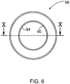
- the valve member 66 which is in the form of an annular ring that is clearly shown in Figures 6 , 9 and 10 , is located adjacent to the closed end portion 82 in its normal or rest position as shown in Figure 5 and Figure 7 . It extends radially outwardly or transversely from the shaft section and thus, when the piston 74 is extended can engage the valve seat 64 to completely close valve port 60.
- the annular valve member 66 and the closed end portion 82 form a reciprocating plug which moves along the central axis to open and close the valve port.
- valve member 66 is slidably mounted on the shaft section 72.
- a return spring 84 is mounted in the valve housing and has one spring end engaging the shaft section 72 so as to bias the shaft section away from the valve seat 64.
- the inner end of the return spring is attached to the closed end portion 82 by being located in a groove formed in a closed end portion.
- the return spring also acts as a stop for preventing the valve member from sliding off the shaft section.
- the shaft section includes an inner annular shoulder 86 and an override coil spring 88 is mounted on the shaft section 72. One end of this spring 88 engages the valve member 66 so as to bias the valve member towards the primary valve seat 64. The other end of the spring 88 rests against the shoulder 86 (see Figure 7 ).
- the illustrated exemplary valve cap 76 has a circular circumference and is inserted into an end portion of the substantially cylindrical cavity that forms the main or first section of the valve chamber.
- the cap has an O-ring seal 96 and is held in position by engaging an annular shoulder 98 of the housing and an opposing snap ring or "C-clip 100" (best shown in Figure 8 ).
- the piston 74 when the temperature inside the chamber 48 drops below the predetermined temperature for the actuator, the piston 74 is able to retract into the actuator body and it is urged to retract into the actuator body by the return spring 84. This retraction will cause the valve member 66 to lift off the valve seat 64, thereby opening the valve port 60.
- the return spring extends through the valve port and into a relatively wide section 104 of the chamber but it does not materially affect the flow through the valve port 60.
- valve cap 76, the actuator 70, the coil spring 88, the valve member 66 and the return spring 84 form a cartridge or sub assembly for the by-pass valve.
- the various conduits can be attached, such as by brazing to the housing, without damaging the actuator or the springs.
- the cartridge can then be installed in the housing 18 and the cap locked in the illustrated position by the C-clip so that the heat exchange circuit will be ready to use.
- the by-pass valve includes a spacer member 110 projecting from and connected to one end of the actuator body. In particular it extends from the same end of the actuator body as the piston 74 with which it is coaxial.
- the spacer member forms a piston-receiving passage 112 into which the piston extends during use of the valve.
- the piston is slidable in this passage and, when fully extended can extend entirely though the passage into the recess 80 formed in the cap.
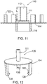
- the spacer member used in the by-pass valve of Figure 5 is shown separately in Figure 11 wherein the length L of the passage 112 is indicated. During use of the valve, the spacer member acts to maintain the adjacent end of the actuator body at least this length L away from the end of the valve chamber.
- An exemplary form of the spacer member is in fact a combined spacer and valve device for use with the thermal by-pass valve.
- This combined device includes a sleeve section 111 which forms the passage 112 that is adapted to receive the piston.
- the combined device further includes a connecting section 116 joined to the plate section on a side thereof opposite the sleeve section and capable of attaching the combined device to the adjacent end of the actuator body.
- valve portion 114 is movable by the actuator 70 between a closed position shown in Figure 5 where flow of the heat exchange fluid (or oil) between the two ports 54, 52 is substantially blocked by the valve portion and an open position where flow between these two ports can take place.
- the exemplary by-pass valve shown has a further valve port 120 located between the second port 52 and the fourth port 54 and it is this second port that can be opened or closed by axial movement of the plate section 114 of the spacer member.
- a further valve port 120 located between the second port 52 and the fourth port 54 and it is this second port that can be opened or closed by axial movement of the plate section 114 of the spacer member.
- guide posts 122 which are integrally formed on the plate section and which are spaced from but parallel to the sleeve section 111.
- there are four of these guide posts distributed evenly about the circumference of the plate section. It will be understood that the guide posts engage a cylindrical wall 124 which defines the circumference of the valve chamber in the section through which the sleeve section 111 extends.
- valve chamber has a wide section 104 having a diameter greater than that of the chamber section formed by the wall 124. Extension of the piston 74 into the end recess 80 will cause the plate section 114 to move axially away from the port 120 and into the wide section 104 of the chamber, thereby permitting heat exchange fluid to flow between the two ports 54, 52. This flow is allowed by the fact that the valve chamber is wider in the section 48.
- the actuator 70 has an enlarged head section 130 at its piston end.
- This head section which has a substantially cylindrical exterior has a diameter greater than the diameter of the cylindrical shaft section 72.
- the override spring 88 engages the shoulder formed by this head section at one end.
- the connecting section 116 is an internally threaded cylindrical section which is threaded onto an end section of the actuator, namely the enlarged head section 130.
- Figure 12 illustrates separately an alternate combined spacer and valve device indicated generally at 135.
- This device has a sleeve section 111 similar to the spacer member used in the embodiment of Figure 5 and it also has a similar plate section 114 with a circular periphery.
- Extending in the same direction as the sleeve section and parallel thereto can be several guide posts similar to those shown on Figure 5 and serving the same function. These posts are not shown in Figure 12 but are shown in part in Figure 13 .
- Extending from the side of the plate section opposite the sleeve section are several resilient hook members 138. These can be integrally formed on the plate section 114 and evenly distributed around the circumference of the plate section. The free end of each hook member is formed with a short end-flange or hook 166.
- the washer-like annular valve member shown in Figures 6 , 9 and 10 can be formed from a synthetic material such as plastic.
- suitable materials for this member can be polyamide 4/6 or polyamide 66, although other suitable nylons and plastics can be used.
- the annular valve member has a substantially smooth cylindrical inner surface 90 defining a central opening 92 through which the shaft section of the actuator extends.
- a circumferential inwardly extending wiper or rib 94 protrudes inward from a mid-point of the surface 90 for slidably engaging the outer surface of the shaft section.
- An exemplary form of the rib 94 has a thickness which is a fraction of that of the valve member itself. In particular, the rib 94 can be 1/3 to 1/7 of the thickness of the valve member 66.
- the illustrated valve member is a unitary structure with the rib being formed integrally with, and from the same material as, the rest of the valve member.
- valve chamber formed by the valve housing has several sections of different widths and a couple of these sections have been described above.
- the wide section 104 as shown has a tapered end portion 140 in the region of the valve member 66 and it has a further tapered portion 142 adjacent the further valve port 120.
- a relatively narrow end section 144 At one end of the wide section 104, is a relatively narrow end section 144 through which the return spring 84 extends.
- This end section can be considered a first end section of the valve chamber.
- the portion of the valve chamber through which the sleeve section 111 extends can be considered a second end section 146 and it is this section which is defined by the aforementioned cylindrical wall 124.
- the second end section is adjacent the fourth port 54 and it has a larger diameter than the first end section 144.
- the wide section 104 can be considered the central section of the chamber and this section is adjacent the second port 52 and contains the actuator. As indicated, this central section has a transverse width greater than the diameter of the second end section 146.
- thermal by-pass valves rather than having a separate spacer and valve device as illustrated in Figure 5 , it is possible to provide the sleeve and the annular valve plate portion as integral extensions of the actuator body itself and not as a separate member.
- the enlarged head section 130 of the actuator, sleeve section 111 and plate section 114 can be molded or formed as an integral, one piece member, if desired. This member can then be attached to the remaining portion of the actuator body during manufacture of the actuator.
- Figure 14 illustrates the internal layout and components of the aforementioned three port by-pass valve constructed according to the present disclosure. Except for the differences noted hereinafter, the by-pass valve 44 is similar to the by-pass valve 14 described above and illustrated in Figure 5 . However, in this embodiment, the single conduit 45 communicates with the end section 150 of the valve chamber. When the by-pass valve member 66 is in the open position, oil from the transmission, for example, can flow from the conduit 36 and upwardly through the conduit 45 and through the valve port. The oil can then flow through the main, wide section 104 of the valve chamber and exit the valve through the port 52.
- valve member 66 When the valve member 66 is in the closed position, so that there is no by-pass flow, oil coming from the transmission through the conduit 36 flows into the conduit 28 and through the heat exchanger to be returned to the transmission through the conduits 32, 34 as in the case of the by-pass valve 14.
- Figure 14 shows the three port by-pass valve 44 provided with a combined spacer and valve device 152, this device having a sleeve section 111 and a plate section 114.
- the plate section 114 can block passage of oil from the port 54 to the port 52.
- the port 52 is located lower (as shown in Figure 14 ) in the valve chamber than the port 54 in order to allow the plate section 114 to act as a second valve member.
- one end of the return spring 84 rests against an annular shoulder 154 formed by the valve housing. This shoulder extends around a third external port 156 to which the conduit 45 is connected.
- the by-pass valves have been described above for use with an automotive transmission oil cooler as the heat exchanger, but these by-pass valves can be used with any other type of heat exchanger, such as a fuel cooling heat exchanger, and for non-automotive applications as well.
- Other types of thermal actuators can be used than a wax-type actuator.
Landscapes
- Engineering & Computer Science (AREA)
- General Engineering & Computer Science (AREA)
- Physics & Mathematics (AREA)
- Mechanical Engineering (AREA)
- General Physics & Mathematics (AREA)
- Automation & Control Theory (AREA)
- Fluid Mechanics (AREA)
- Thermal Sciences (AREA)
- Temperature-Responsive Valves (AREA)
Claims (9)
- Wärmeumgehungsventil für einen Wärmeaustauschkreis, welches aufweist:ein Ventilgehäuse (46), das eine Ventilkammer (48) bildet und eine erste Öffnung (50) für eine Ölzuführungsleitung, eine zweite Öffnung (52) für eine Ölrückführungsleitung, eine dritte Öffnung (53) für eine Wärmetauscher-Zuführungsleitung und eine vierte Öffnung (54) für eine Wärmetauscher-Rückführungsleitung hat, wobei die erste, zweite, dritte und vierte Öffnung mit der Kammer (48) kommunizieren, und weiterhin eine Umgehungsventilöffnung (60) hat, die von einem primären Ventilsitz (64) umgeben ist, wobei die Ventilöffnung (60) in der Kammer (48) angeordnet ist und eine Fluidkommunikation zwischen der ersten (50) und der zweiten (62) Öffnung bereitstellt, wenn die Ventilöffnung (60) geöffnet ist, und das Ventilgehäuse (46) eine Gehäusekappe (76) enthält, die ein Ende der Ventilkammer (48) schließt;einen thermisch empfindlichen Aktuator (70), der einen Aktuatorkörper mit einem Schaftabschnitt (72) und einen bewegbaren Kolben (74), der sich von einem Ende des Aktuatorkörpers weg erstreckt, enthält, wobei der Aktuator (70) in der Kammer (48) installiert und in dieser als Antwort auf das Ausfahren oder Zurückziehen des Kolbens (74) bewegbar ist, wobei der Kolben (74) ausfahrbar ist, um mit dem Gehäuse (46) an oder nahe einem Ende der Kammer (48) in Eingriff zu treten;ein Ventilteil (66), das an dem Schaftabschnitt (72) befestigt und durch das Ausfahren des Kolbens (74) aus einer ersten Position, in der die Ventilöffnung (60) geöffnet ist, in eine zweite Position, in der die Ventilöffnung (60) durch das Ventilteil (66), das in dichtendem Eingriff mit dem Ventilsitz (64) ist, geschlossen ist, bewegbar ist; undeine Rückkehrfeder (84), die in dem Gehäuse (46) befestigt ist und ein mit dem Schaftabschnitt (72) in Eingriff befindliches Federende derart hat, dass der Schaftabschnitt (72) von dem Ventilsitz (64) weg vorgespannt wird und der Aktuator (70) beim Zurückziehen des Kolbens (74) von dem Ventilsitz (64) weg bewegt wird;dadurch gekennzeichnet, dassein Abstandshalterteil (152), das von der Gehäusekappe (76) getrennt ist, von dem Aktuatorkörper und koaxial mit dem Kolben (74) vorsteht, wobei das Abstandshalterteil (152) einen Manschettenabschnitt (111), der einen kolbenaufnehmenden Durchgang (112), in den sich der Kolben (74) während der Verwendung des Umgehungsventils erstreckt, bildet, und einen Verbindungsabschnitt (116), der das Abstandshalterteil (152) mit einem Endabschnitt des Aktuatorkörpers verbindet, enthält, wobei der Kolben (74) in dem Durchgang (112) gleitbar ist,wobei der Durchgang (112) eine Länge hat und während der Verwendung des Ventils das Abstandshalterteil (152) wirksam ist, um das eine Ende des Aktuatorkörpers um zumindest die Länge des Durchgangs (112) von dem einen Ende der Kammer (48) weg zu halten,wobei das Abstandshalterteil (152) einen ringförmigen Plattenabschnitt enthält, der sich in Umfangsrichtung um den Manschettenabschnitt (111) herum erstreckt und einen Ventilbereich bildet, und wobei der Plattenabschnitt (114) durch den Aktuator (70) zwischen einer geschlossenen Ventilposition, in der eine Strömung von Öl zwischen der vierten Öffnung (54) und der zweiten Öffnung (52) blockiert ist, und einer geöffneten Ventilposition, in der eine Strömung von Öl von der vierten Öffnung (54) zu der zweiten Öffnung (52) stattfinden kann, bewegbar ist.
- Wärmeumgehungsventil nach Anspruch 1, bei dem der Aktuator (70) einen vergrößerten Kopfabschnitt (130) an dem einen Ende des Aktuators (70) hat, wobei der Kopfabschnitt (130) einen Durchmesser hat, der größer als der Durchmesser des Schaftabschnitts (72) ist, und das Ventilgehäuse (46) eine weitere Ventilöffnung (120) hat, die sich zwischen der zweiten Öffnung (52) und der vierten Öffnung (54) befindet, und das Abstandshalterteil (152) durch Ausfahren des Kolbens (74) aus einer geschlossenen Position, in der die weitere Ventilöffnung (120) durch das Abstandshalterteil (152) geschlossen ist, in eine Position, in der die weitere Ventilöffnung (120) geöffnet ist, um Öl zu ermöglichen, von der vierten Öffnung (54) zu der zweiten Öffnung (52) zu strömen, bewegbar ist.
- Wärmeumgehungsventil nach Anspruch 2, enthaltend eine Überlagerungsfeder (88), die an dem Schaftabschnitt (72) befestigt ist und deren eines Ende in Eingriff mit dem Ventilteil (66) ist, um das Ventilteil (66) zu dem primären Ventilsitz (64) hin vorzuspannen.
- Wärmeumgehungsventil nach Anspruch 1, bei dem der Verbindungsabschnitt (116) mit dem Plattenabschnitt (114) verbunden und sich von diesem weg erstreckt, und
der Kolben ((74) in dem Durchgang (112), der eine Länge hat, gleitbar ist, und während der Verwendung des Ventils das Abstandshalterteil (15) wirksam ist, um das eine Ende des Aktuatorkörpers über zumindest die Länge des Durchgangs (112) von dem einen Ende der Kammer (48) weg zu halten. - Wärmeumgehungsventil nach Anspruch 4, bei dem der Verbindungsabschnitt (116) ein zylindrischer Abschnitt mit Innengewinde ist, der auf einen Endabschnitt des Aktuators (70) geschraubt ist.
- Wärmeumgehungsventil nach Anspruch 4, bei dem das Abstandshalterteil (152) Führungsteile (122) hat, die um einen äußeren Umfang des Plattenabschnitts (114) herum befestigt und wirksam sind, eine Bewegung des Abstandshalterteils (152) zwischen der geschlossenen und der geöffneten Position zu führen.
- Wärmeumgehungsventil nach Anspruch 1, bei dem sich ein Strömungsdurchgang zwischen der ersten Öffnung (50) und der dritten Öffnung (53) erstreckt und durch das Ventilgehäuse (46) gebildet ist, und die Rückführungsfeder (84) sich über den Strömungsdurchgang erstreckt, wodurch ein anderes Ende der Rückführungsfeder (84) in Eingriff mit einer inneren Oberfläche des Gehäuses (40) ist.
- Wärmeumgehungsventil nach Anspruch 1, bei dem das Ventilgehäuse (46) eine Ventilkappe (76) und einen Hauptkörper des Gehäuses (46), in welchem die Ventilkappe (76) abnehmbar befestigt ist, enthält, wobei die Ventilkappe (76) eine mittlere Vertiefung (80) hat, die in einer Innenfläche hiervon gebildet ist und mit einer mittleren Längsachse des Kolbens (74) ausgerichtet ist, und der Kolben (74) sich in die Vertiefung (80) erstreckt, wenn der Kolben (74) vollständig ausgefahren ist.
- Wärmeumgehungsventil nach Anspruch 1, bei dem die Ventilkammer (48) einen relativ engen ersten Endabschnitt (144), durch den sich die Rückkehrfeder (84) erstreckt, einen zweiten Endabschnitt (146) benachbart der vierten Öffnung (54), der einen größeren Durchmesser als der erste Endabschnitt (144) hat, und einen mittleren Abschnitt (104) benachbart der zweiten Öffnung (52) und den Aktuator (70) enthaltend enthält, wobei der mittlere Abschnitt (104) eine Querbreite hat, die größer als der Durchmesser des zweiten Endabschnitts (146) ist.
Applications Claiming Priority (2)
| Application Number | Priority Date | Filing Date | Title |
|---|---|---|---|
| US12/500,248 US8991719B2 (en) | 2009-07-09 | 2009-07-09 | Low pressure drop thermal by-pass valve |
| PCT/CA2010/001084 WO2011003204A1 (en) | 2009-07-09 | 2010-07-08 | Low pressure drop thermal by-pass valve |
Publications (3)
| Publication Number | Publication Date |
|---|---|
| EP2452108A1 EP2452108A1 (de) | 2012-05-16 |
| EP2452108A4 EP2452108A4 (de) | 2012-12-19 |
| EP2452108B1 true EP2452108B1 (de) | 2017-09-06 |
Family
ID=43426609
Family Applications (1)
| Application Number | Title | Priority Date | Filing Date |
|---|---|---|---|
| EP10796636.8A Not-in-force EP2452108B1 (de) | 2009-07-09 | 2010-07-08 | Wärmeumgehungsventil mit niedrigem druckabfall |
Country Status (6)
| Country | Link |
|---|---|
| US (1) | US8991719B2 (de) |
| EP (1) | EP2452108B1 (de) |
| KR (1) | KR20120039008A (de) |
| CN (1) | CN102472407B (de) |
| CA (1) | CA2766276C (de) |
| WO (1) | WO2011003204A1 (de) |
Cited By (1)
| Publication number | Priority date | Publication date | Assignee | Title |
|---|---|---|---|---|
| EP4137723A4 (de) * | 2020-07-02 | 2024-04-24 | Nippon Thermostat Co., Ltd. | Entlastungsventil und kühlkreislauf damit |
Families Citing this family (48)
| Publication number | Priority date | Publication date | Assignee | Title |
|---|---|---|---|---|
| US9896979B2 (en) * | 2011-02-23 | 2018-02-20 | GM Global Technology Operations LLC | System and method for controlling a temperature of oil in a power-plant of a vehicle |
| EP2683970A1 (de) * | 2011-03-11 | 2014-01-15 | Fluid Automation Systems S.A. | Durch eine flüssigkeitsgekühlte formgedächtnislegierung betätigtes ventil |
| CN102359577A (zh) * | 2011-09-08 | 2012-02-22 | 浙江三花汽车零部件股份有限公司 | 一种车用变速箱调温器 |
| CN102312997A (zh) * | 2011-09-08 | 2012-01-11 | 浙江三花汽车零部件股份有限公司 | 一种车用变速箱调温器 |
| CN102312998A (zh) * | 2011-09-08 | 2012-01-11 | 浙江三花汽车零部件股份有限公司 | 一种车用变速箱调温器 |
| CN102359576A (zh) * | 2011-09-08 | 2012-02-22 | 浙江三花汽车零部件股份有限公司 | 一种车用变速箱调温器 |
| CN102322512A (zh) * | 2011-09-08 | 2012-01-18 | 浙江三花汽车零部件股份有限公司 | 一种车用变速箱调温器 |
| US20130133875A1 (en) * | 2011-11-25 | 2013-05-30 | Hyundai Motor Company | Heat exchanger for vehicle |
| CN103133740B (zh) * | 2011-12-04 | 2015-01-28 | 浙江三花汽车零部件有限公司 | 一种调温器及其阀体的制作方法 |
| CN104822975B (zh) | 2012-08-07 | 2017-12-29 | 浙江三花汽车零部件有限公司 | 一种调温器 |
| CN103574265B (zh) * | 2012-08-07 | 2016-08-17 | 浙江三花汽车零部件有限公司 | 一种用于换热回路的调温器 |
| CN103573958B (zh) * | 2012-08-07 | 2016-04-20 | 浙江三花汽车零部件有限公司 | 一种用于换热回路的调温器组件 |
| WO2014023156A1 (zh) | 2012-08-07 | 2014-02-13 | 浙江三花汽车零部件有限公司 | 一种调温器及调温器组件 |
| CN103574264B (zh) * | 2012-08-07 | 2016-05-25 | 浙江三花汽车零部件有限公司 | 一种用于换热回路的调温器 |
| US9295181B2 (en) * | 2012-11-08 | 2016-03-22 | International Business Machines Corporation | Coolant-conditioning unit with automated control of coolant flow valves |
| US20140205425A1 (en) * | 2013-01-18 | 2014-07-24 | Hamilton Sundstrand Space Systems International | Oil cooling arrangement and method of cooling oil |
| DE102013007186A1 (de) * | 2013-04-25 | 2014-10-30 | Man Truck & Bus Ag | Leitungssystem für ein Kraftfahrzeug |
| US9772632B1 (en) | 2013-11-25 | 2017-09-26 | Richard Michael Ihns | Bypass valve |
| KR101519254B1 (ko) * | 2013-12-09 | 2015-05-11 | 현대자동차주식회사 | 서모바이패스밸브 및 그 고장 제어방법 |
| KR101542989B1 (ko) | 2014-04-30 | 2015-08-07 | 현대자동차 주식회사 | 차량용 밸브 |
| WO2016035910A1 (ko) * | 2014-09-05 | 2016-03-10 | 주식회사 코렌스 | 트랜스미션 오일 바이패스 조립체 |
| KR101610177B1 (ko) | 2014-11-21 | 2016-04-07 | 현대자동차 주식회사 | 차량용 오일 쿨러 |
| KR101610175B1 (ko) | 2014-11-21 | 2016-04-07 | 현대자동차 주식회사 | 차량용 오일 쿨러 |
| KR102108808B1 (ko) * | 2014-12-05 | 2020-05-11 | 현대자동차주식회사 | 온도 감응성이 향상된 atf 오일의 바이패스 밸브 |
| US10619530B2 (en) | 2015-01-26 | 2020-04-14 | Modine Manufacturing Company | Thermal management unit for vehicle powertrain |
| US9765660B2 (en) * | 2015-05-29 | 2017-09-19 | Honeywell International Inc. | Internal bypass to improve decongealing of surface type air to oil coolers |
| KR101744812B1 (ko) | 2015-06-15 | 2017-06-20 | 현대자동차 주식회사 | 차량용 밸브 |
| EP3124907B1 (de) * | 2015-07-29 | 2019-04-10 | Zhejiang Sanhua Automotive Components Co., Ltd. | Wärmetauschervorrichtung |
| CN106481436B (zh) * | 2015-08-25 | 2020-05-15 | 康明斯公司 | 用于发动机的滤头的冷却组件 |
| US9976668B2 (en) * | 2015-08-27 | 2018-05-22 | GM Global Technology Operations LLC | Valve configured regulating the flow of fluid between a device, a heater, and a cooler |
| US20170211715A1 (en) * | 2016-01-21 | 2017-07-27 | GM Global Technology Operations LLC | Oil bypass valve with temporary spacer to provide initially opened fluid circuit |
| ITUB20161064A1 (it) * | 2016-02-25 | 2017-08-25 | Ufi Filters Spa | Valvola di bypass ad azione ritardata |
| WO2017190253A1 (en) | 2016-05-06 | 2017-11-09 | Dana Canada Corporation | Heat exchangers for battery thermal management applications with integrated bypass |
| KR102110828B1 (ko) * | 2016-05-31 | 2020-05-15 | 쯔지앙 산후아 오토모티브 컴포넌츠 컴퍼니 리미티드 | 온도 조절 밸브 |
| USD863360S1 (en) * | 2016-07-22 | 2019-10-15 | Improved Racing Products, LLC | Engine oil line adapter block |
| US9939077B2 (en) * | 2016-08-31 | 2018-04-10 | GM Global Technology Operations LLC | Valve configured for regulating the flow of fluid between a device and a cooler |
| US10082215B2 (en) * | 2016-08-31 | 2018-09-25 | GM Global Technology Operations LLC | Valve configured for regulating the flow of fluid between a device and a cooler |
| CN108608825B (zh) * | 2016-12-09 | 2023-10-20 | 杭州三花研究院有限公司 | 流体换热组件 |
| PL3540352T3 (pl) * | 2016-11-09 | 2023-09-18 | Zhejiang Sanhua Intelligent Controls Co., Ltd. | Zespół wymiany ciepła płynu i układ zarządzania temperaturą w pojeździe |
| US10302208B2 (en) * | 2016-12-05 | 2019-05-28 | Rostra Vernatherm, Llc | Control valve with external relief bias member |
| DE102016124675A1 (de) * | 2016-12-12 | 2018-06-14 | Illinois Tool Works Inc. | Thermostatventil für eine Verbrennungskraftmaschine |
| US10386151B2 (en) | 2017-02-09 | 2019-08-20 | Mcp Ip, Llc | Archery bow with pass through cabling |
| CN111206981A (zh) * | 2018-11-21 | 2020-05-29 | 福特全球技术公司 | 用于冷却散热器布置的控制阀 |
| DE102020204271A1 (de) * | 2019-04-05 | 2020-10-08 | Dana Canada Corporation | Wärmetauscheranordnung mit integriertem Ventil und Druckbypass |
| KR102654462B1 (ko) | 2019-11-04 | 2024-04-03 | 현대자동차 주식회사 | 차량용 밸브 장치 |
| US11333445B1 (en) * | 2020-08-31 | 2022-05-17 | Mainstream Engineering Corporation | Modular membrane controlled three-phase deployable radiator |
| CN114838181B (zh) * | 2021-02-01 | 2025-08-19 | 浙江三花智能控制股份有限公司 | 电磁切换阀 |
| CN114688771B (zh) * | 2022-05-20 | 2022-08-05 | 海尔(深圳)研发有限责任公司 | 单向分流装置及可变分流换热器 |
Family Cites Families (26)
| Publication number | Priority date | Publication date | Assignee | Title |
|---|---|---|---|---|
| US1784042A (en) * | 1927-10-06 | 1930-12-09 | Fulton Sylphon Co | Thermostat support |
| US3255740A (en) * | 1964-09-18 | 1966-06-14 | Gen Motors Corp | Engine coolant deaeration system |
| US4190198A (en) * | 1978-04-12 | 1980-02-26 | Lockhart Industries, Inc. | Oil cooler bypass valve actuating means |
| US4193442A (en) * | 1979-03-19 | 1980-03-18 | Vian David R | Dual bimetal relief valve |
| US4524907A (en) * | 1981-11-05 | 1985-06-25 | Standard-Thomson Corporation | Automotive thermostatic fluid control valve device |
| FR2589219B1 (fr) | 1985-10-28 | 1988-05-13 | Vernet Procedes | Perfectionnements aux vannes mitigeuses thermostatiques pour circuits de refroidissement a liquide de moteurs a combustion interne |
| US4883225A (en) * | 1988-03-18 | 1989-11-28 | S.T.C., Inc. | Fail-safe thermostat for vehicular cooling systems |
| GB2241301A (en) | 1990-02-23 | 1991-08-28 | Western Thomson Controls Ltd | Thermostatically controlled valve for engine cooling system |
| US5271559A (en) * | 1992-09-03 | 1993-12-21 | Chrysler Corporation | Thermal isolation device for heater core to prevent over-heat damage |
| GB9411617D0 (en) * | 1994-06-09 | 1994-08-03 | Rover Group | A thermostat assembly |
| DE29500897U1 (de) * | 1995-01-20 | 1996-05-30 | Behr-Thomson Dehnstoffregler Gmbh & Co, 70806 Kornwestheim | Thermostatventil |
| DE19546440A1 (de) * | 1995-12-13 | 1997-06-19 | Hydac Filtertechnik Gmbh | Filtervorrichtung mit Bypaßventil |
| CA2216451C (en) | 1997-09-24 | 2004-06-22 | Long Manufacturing Ltd. | By-pass valves for heat exchangers |
| US6253837B1 (en) * | 1998-03-23 | 2001-07-03 | Long Manufacturing Ltd. | By-pass values for heat exchanger |
| US7854256B2 (en) * | 2001-07-26 | 2010-12-21 | Dana Canada Corporation | Plug bypass valves and heat exchangers |
| US6499666B1 (en) * | 2001-08-31 | 2002-12-31 | Huron, Inc. | Oil cooler bypass valve |
| US6575707B2 (en) * | 2001-11-05 | 2003-06-10 | Ingersoll-Rand Company | Air compressor having thermal valve |
| GB0310120D0 (en) * | 2003-05-02 | 2003-06-04 | Ford Global Tech Llc | Engine cooling systems |
| CA2457978A1 (en) * | 2004-02-19 | 2005-08-19 | Dana Canada Corporation | Connector assembly for male and female members |
| CA2459088C (en) * | 2004-02-27 | 2012-08-21 | Dana Canada Corporation | Leak-resistant solenoid valve |
| JP4586460B2 (ja) * | 2004-08-30 | 2010-11-24 | トヨタ自動車株式会社 | 自動変速機の熱交換器構造 |
| US7540431B2 (en) * | 2004-11-24 | 2009-06-02 | Dana Canada Corporation | By-pass valve for heat exchanger |
| US7735546B2 (en) * | 2006-10-20 | 2010-06-15 | Ford Global Technologies, Llc | Heat exchanger bypass valve having temperature insensitive pressure bypass function |
| US7721973B2 (en) * | 2007-04-03 | 2010-05-25 | Dana Canada Corporation | Valve |
| US20090026405A1 (en) * | 2007-07-26 | 2009-01-29 | Dana Canada Corporation | Leak resistant by-pass valve |
| US8066197B2 (en) * | 2009-01-15 | 2011-11-29 | Dana Canada Corporation | Failsafe thermal bypass valve for cooling system |
-
2009
- 2009-07-09 US US12/500,248 patent/US8991719B2/en not_active Expired - Fee Related
-
2010
- 2010-07-08 WO PCT/CA2010/001084 patent/WO2011003204A1/en not_active Ceased
- 2010-07-08 CN CN201080030681.6A patent/CN102472407B/zh not_active Expired - Fee Related
- 2010-07-08 EP EP10796636.8A patent/EP2452108B1/de not_active Not-in-force
- 2010-07-08 KR KR1020127003465A patent/KR20120039008A/ko not_active Ceased
- 2010-07-08 CA CA2766276A patent/CA2766276C/en not_active Expired - Fee Related
Non-Patent Citations (1)
| Title |
|---|
| None * |
Cited By (2)
| Publication number | Priority date | Publication date | Assignee | Title |
|---|---|---|---|---|
| EP4137723A4 (de) * | 2020-07-02 | 2024-04-24 | Nippon Thermostat Co., Ltd. | Entlastungsventil und kühlkreislauf damit |
| US12025233B2 (en) | 2020-07-02 | 2024-07-02 | Nippon Thermostat Co., Ltd. | Relief valve and cooling circuit using same |
Also Published As
| Publication number | Publication date |
|---|---|
| KR20120039008A (ko) | 2012-04-24 |
| EP2452108A1 (de) | 2012-05-16 |
| WO2011003204A1 (en) | 2011-01-13 |
| EP2452108A4 (de) | 2012-12-19 |
| US20110005741A1 (en) | 2011-01-13 |
| CN102472407A (zh) | 2012-05-23 |
| CA2766276A1 (en) | 2011-01-13 |
| US8991719B2 (en) | 2015-03-31 |
| CN102472407B (zh) | 2015-07-08 |
| CA2766276C (en) | 2016-08-16 |
Similar Documents
| Publication | Publication Date | Title |
|---|---|---|
| EP2452108B1 (de) | Wärmeumgehungsventil mit niedrigem druckabfall | |
| US8141790B2 (en) | Thermal bypass valve with pressure relief capability | |
| US6253837B1 (en) | By-pass values for heat exchanger | |
| US20090026405A1 (en) | Leak resistant by-pass valve | |
| US7299994B2 (en) | Oil cooler bypass valve | |
| CA2748171C (en) | Failsafe thermal bypass valve for cooling system | |
| US7540431B2 (en) | By-pass valve for heat exchanger | |
| CN109699183B (zh) | 具有双内部阀的热交换器 | |
| US6935569B2 (en) | Oil cooler bypass valve | |
| US10087793B2 (en) | Thermal management unit for vehicle powertrain | |
| EP2884134B1 (de) | Wärmeregler | |
| EP1017928B1 (de) | Bypassventil für wärmetauscher | |
| US6499666B1 (en) | Oil cooler bypass valve | |
| US20030136855A1 (en) | Oil cooler bypass valve | |
| US20110042060A1 (en) | Plug Bypass Valves and Heat Exchangers | |
| US7735546B2 (en) | Heat exchanger bypass valve having temperature insensitive pressure bypass function | |
| EP1815205B1 (de) | Umgehungsventil für wärmetauscher |
Legal Events
| Date | Code | Title | Description |
|---|---|---|---|
| PUAI | Public reference made under article 153(3) epc to a published international application that has entered the european phase |
Free format text: ORIGINAL CODE: 0009012 |
|
| 17P | Request for examination filed |
Effective date: 20120209 |
|
| AK | Designated contracting states |
Kind code of ref document: A1 Designated state(s): AL AT BE BG CH CY CZ DE DK EE ES FI FR GB GR HR HU IE IS IT LI LT LU LV MC MK MT NL NO PL PT RO SE SI SK SM TR |
|
| DAX | Request for extension of the european patent (deleted) | ||
| A4 | Supplementary search report drawn up and despatched |
Effective date: 20121115 |
|
| RIC1 | Information provided on ipc code assigned before grant |
Ipc: F25B 41/04 20060101ALI20121109BHEP Ipc: F01M 5/00 20060101ALI20121109BHEP Ipc: F28F 27/00 20060101ALI20121109BHEP Ipc: F16K 31/64 20060101AFI20121109BHEP Ipc: F16H 57/04 20100101ALI20121109BHEP |
|
| 17Q | First examination report despatched |
Effective date: 20140331 |
|
| GRAP | Despatch of communication of intention to grant a patent |
Free format text: ORIGINAL CODE: EPIDOSNIGR1 |
|
| INTG | Intention to grant announced |
Effective date: 20170301 |
|
| GRAS | Grant fee paid |
Free format text: ORIGINAL CODE: EPIDOSNIGR3 |
|
| GRAA | (expected) grant |
Free format text: ORIGINAL CODE: 0009210 |
|
| AK | Designated contracting states |
Kind code of ref document: B1 Designated state(s): AL AT BE BG CH CY CZ DE DK EE ES FI FR GB GR HR HU IE IS IT LI LT LU LV MC MK MT NL NO PL PT RO SE SI SK SM TR |
|
| REG | Reference to a national code |
Ref country code: GB Ref legal event code: FG4D |
|
| REG | Reference to a national code |
Ref country code: CH Ref legal event code: EP Ref country code: AT Ref legal event code: REF Ref document number: 926262 Country of ref document: AT Kind code of ref document: T Effective date: 20170915 |
|
| REG | Reference to a national code |
Ref country code: IE Ref legal event code: FG4D |
|
| REG | Reference to a national code |
Ref country code: DE Ref legal event code: R082 Ref document number: 602010045078 Country of ref document: DE Representative=s name: PFENNING, MEINIG & PARTNER MBB PATENTANWAELTE, DE |
|
| REG | Reference to a national code |
Ref country code: DE Ref legal event code: R096 Ref document number: 602010045078 Country of ref document: DE |
|
| REG | Reference to a national code |
Ref country code: NL Ref legal event code: MP Effective date: 20170906 |
|
| REG | Reference to a national code |
Ref country code: LT Ref legal event code: MG4D |
|
| PG25 | Lapsed in a contracting state [announced via postgrant information from national office to epo] |
Ref country code: LT Free format text: LAPSE BECAUSE OF FAILURE TO SUBMIT A TRANSLATION OF THE DESCRIPTION OR TO PAY THE FEE WITHIN THE PRESCRIBED TIME-LIMIT Effective date: 20170906 Ref country code: SE Free format text: LAPSE BECAUSE OF FAILURE TO SUBMIT A TRANSLATION OF THE DESCRIPTION OR TO PAY THE FEE WITHIN THE PRESCRIBED TIME-LIMIT Effective date: 20170906 Ref country code: HR Free format text: LAPSE BECAUSE OF FAILURE TO SUBMIT A TRANSLATION OF THE DESCRIPTION OR TO PAY THE FEE WITHIN THE PRESCRIBED TIME-LIMIT Effective date: 20170906 Ref country code: FI Free format text: LAPSE BECAUSE OF FAILURE TO SUBMIT A TRANSLATION OF THE DESCRIPTION OR TO PAY THE FEE WITHIN THE PRESCRIBED TIME-LIMIT Effective date: 20170906 Ref country code: NO Free format text: LAPSE BECAUSE OF FAILURE TO SUBMIT A TRANSLATION OF THE DESCRIPTION OR TO PAY THE FEE WITHIN THE PRESCRIBED TIME-LIMIT Effective date: 20171206 |
|
| REG | Reference to a national code |
Ref country code: AT Ref legal event code: MK05 Ref document number: 926262 Country of ref document: AT Kind code of ref document: T Effective date: 20170906 |
|
| PG25 | Lapsed in a contracting state [announced via postgrant information from national office to epo] |
Ref country code: BG Free format text: LAPSE BECAUSE OF FAILURE TO SUBMIT A TRANSLATION OF THE DESCRIPTION OR TO PAY THE FEE WITHIN THE PRESCRIBED TIME-LIMIT Effective date: 20171206 Ref country code: LV Free format text: LAPSE BECAUSE OF FAILURE TO SUBMIT A TRANSLATION OF THE DESCRIPTION OR TO PAY THE FEE WITHIN THE PRESCRIBED TIME-LIMIT Effective date: 20170906 Ref country code: GR Free format text: LAPSE BECAUSE OF FAILURE TO SUBMIT A TRANSLATION OF THE DESCRIPTION OR TO PAY THE FEE WITHIN THE PRESCRIBED TIME-LIMIT Effective date: 20171207 Ref country code: ES Free format text: LAPSE BECAUSE OF FAILURE TO SUBMIT A TRANSLATION OF THE DESCRIPTION OR TO PAY THE FEE WITHIN THE PRESCRIBED TIME-LIMIT Effective date: 20170906 |
|
| PG25 | Lapsed in a contracting state [announced via postgrant information from national office to epo] |
Ref country code: NL Free format text: LAPSE BECAUSE OF FAILURE TO SUBMIT A TRANSLATION OF THE DESCRIPTION OR TO PAY THE FEE WITHIN THE PRESCRIBED TIME-LIMIT Effective date: 20170906 |
|
| PG25 | Lapsed in a contracting state [announced via postgrant information from national office to epo] |
Ref country code: RO Free format text: LAPSE BECAUSE OF FAILURE TO SUBMIT A TRANSLATION OF THE DESCRIPTION OR TO PAY THE FEE WITHIN THE PRESCRIBED TIME-LIMIT Effective date: 20170906 Ref country code: CZ Free format text: LAPSE BECAUSE OF FAILURE TO SUBMIT A TRANSLATION OF THE DESCRIPTION OR TO PAY THE FEE WITHIN THE PRESCRIBED TIME-LIMIT Effective date: 20170906 Ref country code: PL Free format text: LAPSE BECAUSE OF FAILURE TO SUBMIT A TRANSLATION OF THE DESCRIPTION OR TO PAY THE FEE WITHIN THE PRESCRIBED TIME-LIMIT Effective date: 20170906 |
|
| PG25 | Lapsed in a contracting state [announced via postgrant information from national office to epo] |
Ref country code: SM Free format text: LAPSE BECAUSE OF FAILURE TO SUBMIT A TRANSLATION OF THE DESCRIPTION OR TO PAY THE FEE WITHIN THE PRESCRIBED TIME-LIMIT Effective date: 20170906 Ref country code: AT Free format text: LAPSE BECAUSE OF FAILURE TO SUBMIT A TRANSLATION OF THE DESCRIPTION OR TO PAY THE FEE WITHIN THE PRESCRIBED TIME-LIMIT Effective date: 20170906 Ref country code: SK Free format text: LAPSE BECAUSE OF FAILURE TO SUBMIT A TRANSLATION OF THE DESCRIPTION OR TO PAY THE FEE WITHIN THE PRESCRIBED TIME-LIMIT Effective date: 20170906 Ref country code: IS Free format text: LAPSE BECAUSE OF FAILURE TO SUBMIT A TRANSLATION OF THE DESCRIPTION OR TO PAY THE FEE WITHIN THE PRESCRIBED TIME-LIMIT Effective date: 20180106 Ref country code: IT Free format text: LAPSE BECAUSE OF FAILURE TO SUBMIT A TRANSLATION OF THE DESCRIPTION OR TO PAY THE FEE WITHIN THE PRESCRIBED TIME-LIMIT Effective date: 20170906 Ref country code: EE Free format text: LAPSE BECAUSE OF FAILURE TO SUBMIT A TRANSLATION OF THE DESCRIPTION OR TO PAY THE FEE WITHIN THE PRESCRIBED TIME-LIMIT Effective date: 20170906 |
|
| REG | Reference to a national code |
Ref country code: DE Ref legal event code: R097 Ref document number: 602010045078 Country of ref document: DE |
|
| PLBE | No opposition filed within time limit |
Free format text: ORIGINAL CODE: 0009261 |
|
| STAA | Information on the status of an ep patent application or granted ep patent |
Free format text: STATUS: NO OPPOSITION FILED WITHIN TIME LIMIT |
|
| REG | Reference to a national code |
Ref country code: FR Ref legal event code: PLFP Year of fee payment: 9 |
|
| PG25 | Lapsed in a contracting state [announced via postgrant information from national office to epo] |
Ref country code: DK Free format text: LAPSE BECAUSE OF FAILURE TO SUBMIT A TRANSLATION OF THE DESCRIPTION OR TO PAY THE FEE WITHIN THE PRESCRIBED TIME-LIMIT Effective date: 20170906 |
|
| 26N | No opposition filed |
Effective date: 20180607 |
|
| PG25 | Lapsed in a contracting state [announced via postgrant information from national office to epo] |
Ref country code: SI Free format text: LAPSE BECAUSE OF FAILURE TO SUBMIT A TRANSLATION OF THE DESCRIPTION OR TO PAY THE FEE WITHIN THE PRESCRIBED TIME-LIMIT Effective date: 20170906 |
|
| REG | Reference to a national code |
Ref country code: CH Ref legal event code: PL |
|
| GBPC | Gb: european patent ceased through non-payment of renewal fee |
Effective date: 20180708 |
|
| PG25 | Lapsed in a contracting state [announced via postgrant information from national office to epo] |
Ref country code: MC Free format text: LAPSE BECAUSE OF FAILURE TO SUBMIT A TRANSLATION OF THE DESCRIPTION OR TO PAY THE FEE WITHIN THE PRESCRIBED TIME-LIMIT Effective date: 20170906 Ref country code: LU Free format text: LAPSE BECAUSE OF NON-PAYMENT OF DUE FEES Effective date: 20180708 |
|
| REG | Reference to a national code |
Ref country code: BE Ref legal event code: MM Effective date: 20180731 |
|
| REG | Reference to a national code |
Ref country code: IE Ref legal event code: MM4A |
|
| PG25 | Lapsed in a contracting state [announced via postgrant information from national office to epo] |
Ref country code: GB Free format text: LAPSE BECAUSE OF NON-PAYMENT OF DUE FEES Effective date: 20180708 Ref country code: CH Free format text: LAPSE BECAUSE OF NON-PAYMENT OF DUE FEES Effective date: 20180731 Ref country code: IE Free format text: LAPSE BECAUSE OF NON-PAYMENT OF DUE FEES Effective date: 20180708 Ref country code: LI Free format text: LAPSE BECAUSE OF NON-PAYMENT OF DUE FEES Effective date: 20180731 |
|
| PG25 | Lapsed in a contracting state [announced via postgrant information from national office to epo] |
Ref country code: BE Free format text: LAPSE BECAUSE OF NON-PAYMENT OF DUE FEES Effective date: 20180731 |
|
| PGFP | Annual fee paid to national office [announced via postgrant information from national office to epo] |
Ref country code: FR Payment date: 20190725 Year of fee payment: 10 |
|
| PG25 | Lapsed in a contracting state [announced via postgrant information from national office to epo] |
Ref country code: MT Free format text: LAPSE BECAUSE OF NON-PAYMENT OF DUE FEES Effective date: 20180708 |
|
| PG25 | Lapsed in a contracting state [announced via postgrant information from national office to epo] |
Ref country code: TR Free format text: LAPSE BECAUSE OF FAILURE TO SUBMIT A TRANSLATION OF THE DESCRIPTION OR TO PAY THE FEE WITHIN THE PRESCRIBED TIME-LIMIT Effective date: 20170906 |
|
| PG25 | Lapsed in a contracting state [announced via postgrant information from national office to epo] |
Ref country code: PT Free format text: LAPSE BECAUSE OF FAILURE TO SUBMIT A TRANSLATION OF THE DESCRIPTION OR TO PAY THE FEE WITHIN THE PRESCRIBED TIME-LIMIT Effective date: 20170906 Ref country code: HU Free format text: LAPSE BECAUSE OF FAILURE TO SUBMIT A TRANSLATION OF THE DESCRIPTION OR TO PAY THE FEE WITHIN THE PRESCRIBED TIME-LIMIT; INVALID AB INITIO Effective date: 20100708 |
|
| PG25 | Lapsed in a contracting state [announced via postgrant information from national office to epo] |
Ref country code: CY Free format text: LAPSE BECAUSE OF FAILURE TO SUBMIT A TRANSLATION OF THE DESCRIPTION OR TO PAY THE FEE WITHIN THE PRESCRIBED TIME-LIMIT Effective date: 20170906 Ref country code: MK Free format text: LAPSE BECAUSE OF NON-PAYMENT OF DUE FEES Effective date: 20170906 |
|
| PG25 | Lapsed in a contracting state [announced via postgrant information from national office to epo] |
Ref country code: AL Free format text: LAPSE BECAUSE OF FAILURE TO SUBMIT A TRANSLATION OF THE DESCRIPTION OR TO PAY THE FEE WITHIN THE PRESCRIBED TIME-LIMIT Effective date: 20170906 |
|
| PG25 | Lapsed in a contracting state [announced via postgrant information from national office to epo] |
Ref country code: FR Free format text: LAPSE BECAUSE OF NON-PAYMENT OF DUE FEES Effective date: 20200731 |
|
| PGFP | Annual fee paid to national office [announced via postgrant information from national office to epo] |
Ref country code: DE Payment date: 20210622 Year of fee payment: 12 |
|
| REG | Reference to a national code |
Ref country code: DE Ref legal event code: R119 Ref document number: 602010045078 Country of ref document: DE |
|
| PG25 | Lapsed in a contracting state [announced via postgrant information from national office to epo] |
Ref country code: DE Free format text: LAPSE BECAUSE OF NON-PAYMENT OF DUE FEES Effective date: 20230201 |