EP2452384B1 - Verlustarmer akkumulator - Google Patents
Verlustarmer akkumulator Download PDFInfo
- Publication number
- EP2452384B1 EP2452384B1 EP10729874.7A EP10729874A EP2452384B1 EP 2452384 B1 EP2452384 B1 EP 2452384B1 EP 10729874 A EP10729874 A EP 10729874A EP 2452384 B1 EP2452384 B1 EP 2452384B1
- Authority
- EP
- European Patent Office
- Prior art keywords
- battery
- accumulators
- storage cells
- circuit
- parallel
- Prior art date
- Legal status (The legal status is an assumption and is not a legal conclusion. Google has not performed a legal analysis and makes no representation as to the accuracy of the status listed.)
- Not-in-force
Links
Images


Classifications
-
- H—ELECTRICITY
- H01—ELECTRIC ELEMENTS
- H01M—PROCESSES OR MEANS, e.g. BATTERIES, FOR THE DIRECT CONVERSION OF CHEMICAL ENERGY INTO ELECTRICAL ENERGY
- H01M50/00—Constructional details or processes of manufacture of the non-active parts of electrochemical cells other than fuel cells, e.g. hybrid cells
- H01M50/50—Current conducting connections for cells or batteries
- H01M50/502—Interconnectors for connecting terminals of adjacent batteries; Interconnectors for connecting cells outside a battery casing
-
- H—ELECTRICITY
- H01—ELECTRIC ELEMENTS
- H01M—PROCESSES OR MEANS, e.g. BATTERIES, FOR THE DIRECT CONVERSION OF CHEMICAL ENERGY INTO ELECTRICAL ENERGY
- H01M10/00—Secondary cells; Manufacture thereof
- H01M10/42—Methods or arrangements for servicing or maintenance of secondary cells or secondary half-cells
- H01M10/4207—Methods or arrangements for servicing or maintenance of secondary cells or secondary half-cells for several batteries or cells simultaneously or sequentially
-
- H—ELECTRICITY
- H01—ELECTRIC ELEMENTS
- H01M—PROCESSES OR MEANS, e.g. BATTERIES, FOR THE DIRECT CONVERSION OF CHEMICAL ENERGY INTO ELECTRICAL ENERGY
- H01M10/00—Secondary cells; Manufacture thereof
- H01M10/05—Accumulators with non-aqueous electrolyte
- H01M10/052—Li-accumulators
- H01M10/0525—Rocking-chair batteries, i.e. batteries with lithium insertion or intercalation in both electrodes; Lithium-ion batteries
-
- H—ELECTRICITY
- H01—ELECTRIC ELEMENTS
- H01M—PROCESSES OR MEANS, e.g. BATTERIES, FOR THE DIRECT CONVERSION OF CHEMICAL ENERGY INTO ELECTRICAL ENERGY
- H01M50/00—Constructional details or processes of manufacture of the non-active parts of electrochemical cells other than fuel cells, e.g. hybrid cells
- H01M50/50—Current conducting connections for cells or batteries
- H01M50/502—Interconnectors for connecting terminals of adjacent batteries; Interconnectors for connecting cells outside a battery casing
- H01M50/509—Interconnectors for connecting terminals of adjacent batteries; Interconnectors for connecting cells outside a battery casing characterised by the type of connection, e.g. mixed connections
- H01M50/51—Connection only in series
-
- H—ELECTRICITY
- H01—ELECTRIC ELEMENTS
- H01M—PROCESSES OR MEANS, e.g. BATTERIES, FOR THE DIRECT CONVERSION OF CHEMICAL ENERGY INTO ELECTRICAL ENERGY
- H01M2220/00—Batteries for particular applications
- H01M2220/20—Batteries in motive systems, e.g. vehicle, ship, plane
-
- H—ELECTRICITY
- H02—GENERATION; CONVERSION OR DISTRIBUTION OF ELECTRIC POWER
- H02J—ELECTRIC POWER NETWORKS; CIRCUIT ARRANGEMENTS OR SYSTEMS FOR SUPPLYING OR DISTRIBUTING ELECTRIC POWER; SYSTEMS FOR STORING ELECTRIC ENERGY
- H02J7/00—Circuit arrangements for charging or discharging batteries or for supplying loads from batteries
- H02J7/50—Circuit arrangements for charging or discharging batteries or for supplying loads from batteries acting upon multiple batteries simultaneously or sequentially
-
- Y—GENERAL TAGGING OF NEW TECHNOLOGICAL DEVELOPMENTS; GENERAL TAGGING OF CROSS-SECTIONAL TECHNOLOGIES SPANNING OVER SEVERAL SECTIONS OF THE IPC; TECHNICAL SUBJECTS COVERED BY FORMER USPC CROSS-REFERENCE ART COLLECTIONS [XRACs] AND DIGESTS
- Y02—TECHNOLOGIES OR APPLICATIONS FOR MITIGATION OR ADAPTATION AGAINST CLIMATE CHANGE
- Y02E—REDUCTION OF GREENHOUSE GAS [GHG] EMISSIONS, RELATED TO ENERGY GENERATION, TRANSMISSION OR DISTRIBUTION
- Y02E60/00—Enabling technologies; Technologies with a potential or indirect contribution to GHG emissions mitigation
- Y02E60/10—Energy storage using batteries
-
- Y—GENERAL TAGGING OF NEW TECHNOLOGICAL DEVELOPMENTS; GENERAL TAGGING OF CROSS-SECTIONAL TECHNOLOGIES SPANNING OVER SEVERAL SECTIONS OF THE IPC; TECHNICAL SUBJECTS COVERED BY FORMER USPC CROSS-REFERENCE ART COLLECTIONS [XRACs] AND DIGESTS
- Y02—TECHNOLOGIES OR APPLICATIONS FOR MITIGATION OR ADAPTATION AGAINST CLIMATE CHANGE
- Y02P—CLIMATE CHANGE MITIGATION TECHNOLOGIES IN THE PRODUCTION OR PROCESSING OF GOODS
- Y02P70/00—Climate change mitigation technologies in the production process for final industrial or consumer products
- Y02P70/50—Manufacturing or production processes characterised by the final manufactured product
-
- Y—GENERAL TAGGING OF NEW TECHNOLOGICAL DEVELOPMENTS; GENERAL TAGGING OF CROSS-SECTIONAL TECHNOLOGIES SPANNING OVER SEVERAL SECTIONS OF THE IPC; TECHNICAL SUBJECTS COVERED BY FORMER USPC CROSS-REFERENCE ART COLLECTIONS [XRACs] AND DIGESTS
- Y02—TECHNOLOGIES OR APPLICATIONS FOR MITIGATION OR ADAPTATION AGAINST CLIMATE CHANGE
- Y02T—CLIMATE CHANGE MITIGATION TECHNOLOGIES RELATED TO TRANSPORTATION
- Y02T10/00—Road transport of goods or passengers
- Y02T10/60—Other road transportation technologies with climate change mitigation effect
- Y02T10/70—Energy storage systems for electromobility, e.g. batteries
Definitions
- the invention relates to electrochemical storage batteries. These can for example be used in the field of electric and hybrid transport or embedded systems.
- Lithium-ion type batteries are well suited for transport applications by their ability to store a large amount of energy in a low mass.
- iron phosphate batteries offer a high level of intrinsic safety compared to lithium-ion batteries based on cobalt oxide, to the detriment of a slightly lower specific energy.
- lithium-ion batteries also have a minimum voltage below which a battery can be damaged.
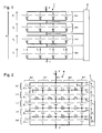
- the figure 1 represents a lithium-ion storage battery 1 known from the state of the art.
- the battery 1 is composed of four stages Et1, Et2, Et3 and Et4 connected in series. Each stage has four similar accumulators connected in parallel. The terminals of the accumulators of the same stage are connected together via electrical connections of large section. Each stage is also connected to the adjacent stages by means of electrical connections of large section in order to pass strong currents corresponding to the sum of the currents of the accumulators of a stage.
- One or more loads are intended to be connected to the terminals N and P of the battery 1.
- the voltage across the four stages is denoted respectively U1, U2, U3 and U4.
- the total voltage U between the terminals N and P of the battery 1 is the sum of the voltages U1, U2, U3 and U4.
- the current flowing through each fourth stage accumulator Et4 is denoted respectively I1, I2, I3 and I4.
- the current I generated on the terminal P of the battery 1 is the sum of currents I1, I2, I3 and I4.
- each accumulator In order to protect the battery 1 from the consequences of a short circuit in an accumulator, each accumulator has a fuse connected to it in series. When an accumulator forms a short circuit, the current flowing therethrough increases substantially and melts its series fuse in order to protect the rest of the battery 1. In the absence of a fuse, the dissipation of energy in the battery in short -circuit induce its heating and that of other accumulators discharging. Such dissipation could be the cause of a fire. Lithium-ion technologies based on cobalt oxide and iron phosphate are particularly at risk when a stage includes a large number of batteries in parallel to store a large amount of energy. The use of fuses is therefore particularly appropriate for these technologies.
- a charged accumulator results in a growth of the voltage at its terminals.
- a charged accumulator is considered when it has reached a nominal voltage level defined by its electrochemical process. If charging is interrupted before this voltage is reached, the battery is not fully charged.
- a fault on an accumulator usually results either by shorting the accumulator, or by an open circuit, or by a large leakage current in the accumulator. It is important to know the impact of battery failure on the battery. Open or short-circuiting may cause an overall failure of the entire battery.
- the battery behaves like a resistor which causes a discharge of the accumulators of the considered stage to zero.
- the risks of starting fire are low because the energy is dissipated relatively slowly.
- the discharge of the accumulators of the stage up to a zero voltage deteriorates them, which implies their replacement in addition to the initially defective accumulator.
- the other three accumulators of the stage will initially discharge into this accumulator, because of the strong section of the electrical connections between them.
- the fuse placed in series with the battery in short circuit will interrupt the parasitic discharge of the other three accumulators.
- Such a battery has a number of disadvantages.
- the fuses are sized to be traversed by large currents, and thus induce significant additional cost.
- the internal resistance of the fuses increases the Joule losses inside the battery, which significantly reduces its performance in power.
- the document US6051955 discloses a storage battery comprising two branches connected in parallel. Each branch includes 3 accumulators connected in series. These accumulators are charged and discharged via two output terminals. Protection transistors are interposed between one of the output terminals and each battery branch. A monitoring circuit detects an excessive charge or discharge of the elements. If this is the case, the monitoring circuit opens the protection transistors between the output terminal and the accumulator branches.
- Each accumulator of one branch is connected in parallel with an accumulator of the other branch.
- Two fuses connected in series thus connect two respective accumulators.
- the monitoring circuit is connected to each node between two fuses in series.
- This accumulator battery further comprises fuses connected in series between a branch and a protective transistor.
- each branch has four accumulators connected in series.
- the accumulators of the two branches are of different types: the first branch comprises high-power accumulators, while the second branch comprises accumulators of high capacity.
- Each high capacity accumulator is connected in parallel with a high power accumulator via a resistor.
- This battery has in practice disadvantages. High power batteries do not significantly improve battery capacity. Moreover, the battery is in practice not protected from certain malfunctions. Thus, a short circuit in an accumulator can induce an overcurrent in the accumulator to which it is connected in parallel via a resistor. Since the accumulators of the two branches are of different types, no compensation can be envisaged in the event of a battery failure.
- the invention aims to solve one or more of these disadvantages without altering the level of security provided by the battery.
- the invention thus relates to an accumulator battery, comprising at least first and second branches each having at least first and second accumulators connected in series, the battery further comprising a circuit breaker through which the first accumulators are connected. in parallel and through which the second accumulators are connected in parallel.
- the breaking threshold of the circuit breaker is sized to conduct the current when one of said accumulators forms an open circuit.
- the battery comprises a third branch having first and second accumulators connected in series, the battery further comprising another circuit breaker through which the first accumulators are connected in parallel and through which the second accumulators are connected in parallel.
- said first accumulators form a first stage of the battery and said second accumulators form a second stage of the battery, the battery further comprising a circuit for balancing the charge of the accumulators connected to the terminals of each stage.
- each junction between the accumulators in parallel is connected to the balancing circuit.
- the accumulators of the first and third branches are non-adjacent, and the balancing circuit is connected to the terminals of the accumulators of the first and third branches.
- the section of the junction between the accumulators in parallel is less than the section of the junction between the accumulators in series.
- the circuit breaker comprises a fusible electrical connection.
- the breaking threshold of the circuit breaker is sized to open when one of said accumulators is short-circuited.
- said accumulators are of a type for which the application of a voltage at their upper terminals of 15% to their nominal voltage does not induce their destruction.
- the accumulators are of the lithium-ion type.
- said branches are devoid of protection circuit breakers arranged in series with said accumulators.
- the internal resistance of said accumulators is lower than the internal resistance of said circuit breaker.
- the invention proposes a battery comprising at least first and second branches each having at least first and second accumulators connected in series, the battery further comprising a circuit breaker through which the first accumulators are connected in parallel and by the intermediate of which the second accumulators are connected in parallel.
- the breaking threshold of the circuit breaker is sized to conduct current when one of said accumulators forms an open circuit.
- the circuit breaker effectively protects the batteries of the battery against overcurrent during a malfunction, at a reduced cost and with less dissipation by Joule effect in normal operation.
- the circuit breaker makes it possible to continue using the battery by allowing all the functional accumulators to compensate for the failure of a battery in a circuit breaker.
- the figure 2 represents a battery 4 according to a first embodiment of the invention.
- the battery 4 has a positive terminal P and a negative terminal N. One or more charges can be connected between the terminals P and N.
- the battery 4 comprises several branches Br1 to Br5. In the example illustrated, the battery 4 comprises five branches. An index j will then correspond to the branch Br j .
- Each branch Br j comprises several accumulators E i, j connected in series, of lithium-ion type based on iron phosphate.
- Branch Br 1 includes accumulators E 1.1 , E 2.1 , E 3.1 , E 4.1 and E 5.1 .
- each branch Br j comprises five accumulators E i, j .
- An index i will subsequently correspond to a stage Et i including five accumulators respectively belonging to each of the branches.
- a breaker is generally designated by a circuit breaker to prevent the passage of electric current and making this interruption in case of overload to protect the components to which it is connected.
- the accumulators E 1, j of the first stage Et 1 are connected in parallel.
- the accumulators E 1, j are connected by their positive terminal to the terminal P of the battery 4.
- the connection of these positive terminals to the terminal P is advantageously achieved by connectors of large section because this connection has a function of collector currents parallel of the different branches.
- the negative terminals of the accumulators E 1, j of the first stage Et 1 are connected together via circuit breakers.
- the circuit breaker D 2.1 connects the negative terminal of the battery E 1.1 to the negative terminal of the battery E 1.2 .
- the accumulators E 2, j of the second stage Et 2 are also connected in parallel.
- the accumulators E 3, j of the third stage Et 3 on the one hand, and the accumulators E 4, j of the fourth stage Et 4 on the other hand, are also connected in parallel.
- the positive terminals of the accumulators of the same stage are connected together via circuit breakers and their negative terminals are also connected together via circuit breakers.
- each circuit breaker is used for a parallel connection for two adjacent stages (two stages sharing connection nodes).
- the circuit breaker D 2.1 is used to connect in parallel the accumulators E 1.1 and E 1.2 but also to connect in parallel the accumulators E 2.1 and E 2.2 .
- the accumulators E 5, j of the fifth stage Et 5 are connected in parallel.
- the positive terminals of the accumulators E 5, j of the fifth stage Et 5 are connected together via circuit breakers.
- the circuit breaker D 5.1 connects the positive terminal of the battery E 5.1 to the positive terminal of the battery E 5.2 .
- the accumulators E 5, j are connected by their negative terminal to the N terminal of the battery 4. The connection of these negative terminals to the N terminal is advantageously carried out by connectors of large section because this connection has a function of introducing the parallel currents in the different branches.
- a charging and balancing circuit 5 is connected to the terminals of each of the stages. Those skilled in the art will determine a suitable circuit 5 for balancing the voltages of the accumulators of each stage and manage the charge of each of the accumulators.
- the current passing through an accumulator E i, j is denoted I i, j .
- the current flowing through a circuit breaker D i, j is denoted It i, j .
- the voltage across a stage i is denoted U i .
- the current exchanged by the positive terminals of a stage i with the charging and balancing circuit 5 is denoted by leq (i) .
- a circuit breaker is defined as being an electrical protection device whose function is to interrupt or limit very strongly (for example by a factor of 100) the electric current passing through it in the event of an overload on an electric circuit.
- the sizing of the circuit breakers of the illustrated example will be detailed later.
- the figure 3 represents a theoretical example of battery 4 in normal operation, in the presence of a load 3 connected between its terminals P and N.
- the load 3 is likened to a resistance of 0.2Ohms.
- Each accumulator is assimilated to a voltage source of 3.3V in series with a resistance of 0.01Ohms (representative of its internal resistance).
- Circuit breakers are considered to be 0.0150hms resistors with a threshold of cutoff is at 6A.
- the connection between the series accumulators of the same branch is suitably dimensioned to withstand the rated current of the branch.
- the accumulators are in this example at their maximum load and all have the same load. Thus, no current flows through the circuit breakers. Thus, in normal operation, the circuit breakers do not induce losses by Joule effect since the currents passing through them are zero. The losses by Joule effect inside the battery 4 are here only induced by the internal resistance of the accumulators. The power efficiency of the battery is thus optimized.
- Each branch is traversed by a current of 15.7A, inducing a current of 78.5A (rounded values) through the load 3.
- the circuit breakers are arranged in parallel connections between the accumulators. In normal operation, these connections must only be traversed by reduced currents during charging or balancing of the various accumulators (in particular at the end of charge of the battery 4). The currents flowing through the circuit breakers during normal operation always remain below their cutoff threshold. Therefore, the size of the circuit breakers used may be significantly smaller than that which would be necessary for circuit breakers arranged in series. It can also be noted that the number of circuit breakers used is less than that which would be necessary for series circuit breakers. The cost of the battery 4 is thus significantly reduced.
- the circuit-breakers have a cutoff threshold lower than the maximum charge or discharge current tolerated for a battery.
- the cut-off threshold is 6A and is significantly lower than the current of 15.7A passing through each of the accumulators at the figure 3 .
- the figure 4 illustrates theoretical current values, assuming that the accumulator E 3.3 forms a short-circuit and in the absence of a break by the circuit-breakers. Assuming that the maximum charging or discharging current of an accumulator is 30A, it is found that all the accumulators of the third stage would be susceptible to deterioration. It can be seen that the parallel connections between the accumulators are subjected to more or less significant currents.
- the circuit-breakers D 2.2 , D 2.3 , D 3.2 , D 3.3 , D 4.2 , D 4.3 D 5.2 , and D 5.3 would be traversed by currents greater than their threshold. cut.
- the circuit breakers D 2.2 , D 2.3 , D 3.2 , D 3.3 , D 4.2 , D 4.3 D 5.2 , and D 5.3 are open because of the overcurrents induced by the battery E 3.3 . Overcurrents are thus limited in time, which eliminates any risk of fire starting by heating an accumulator.
- Overcurrents are thus limited in time, which eliminates any risk of fire starting by heating an accumulator.
- This negative current makes it possible to charge the accumulators E 1.3 , E 2.3 , E 4.3 and E 5.3 up to a voltage of 3.88V to compensate for the failure of the battery E 3.3 in short -circuit.
- branches Br 1 , Br 2 , Br 3 and Br 4 are traversed by a current of 19.4A, lower than the rated current of 30A accumulators.
- the accumulators of the various branches are thus well protected against overcurrents induced by a short circuit in one of the accumulators.
- the transverse currents It i, j are zero.
- the current passing through the load 3 is 77.6A, which is close to the normal running current of the battery 4.
- the figure 6 represents discharge profiles of the battery 4 respectively in normal operation (solid line) and in the presence of a short-circuited battery (broken line). It is found that the voltage between terminals N and P of the battery 4 at full load is maintained at the same level.
- the discharge limit threshold S of the battery 4 is reached earlier at a time T2. In normal operation, this discharge threshold is only reached at a time T1. The performance of the battery 4 is thus reduced in the presence of the failure.
- the circuit 3 can detect the failure of an accumulator by noting a decrease in the discharge duration below a predefined threshold. This failure can be reported to the user of the battery 4 to signal the need for repair.
- the battery 4 still remains functional for several charge / discharge cycles before repair. Since the circuit breakers have prevented deterioration of other accumulators, the repair may consist of changing only the faulty accumulator.
- the figure 7 illustrates the battery 4 during a failure of an accumulator forming an open circuit or circuit breaker, in this case the battery E 3.3 .
- the circuit breakers forming parallel connections allow the other accumulators to compensate for the failure of the accumulator E 3.3 .
- the circuit breakers D 2.1 , D 2.4 , D 5.1 and D 5.4 are traversed by a current of 0.5A.
- the circuit breakers D 3.1 , D 3.4 , D 4.1 and D 4.4 are traversed by a current of 0.9A.
- the circuit breakers D 2.2 , D 2.3 , D 5.2 and D 5.3 are traversed by a current of 1.4A.
- the circuit breakers D 3.2 , D 3.3 , D 4.2 and D 4.3 are crossed by a current of 5.3A. Thus, none of the currents flowing through the circuit breakers exceeds the breaking threshold of these circuit breakers. Thus, all the functional accumulators are discharged, the capacity of the battery 4 thus being reduced to a small extent. The battery 4 therefore remains functional for a number of charge / discharge cycles.
- the accumulators E 1, j of the first stage Et 1 are traversed respectively by currents of 16.6A, 15.7A, 13, 6A, 15.7A and 16.6A, lower than the nominal limit of each of these accumulators.
- the circuit 5 will be able to identify the failure of the accumulator E 3.3 , in particular because of the faster discharge of the stage Et 3 . This failure can be reported to the user of the battery 4 to signal the need for repair.
- the sizing of the circuit breakers is advantageously carried out so that a short-circuited accumulator induces a cut-off by at least one circuit breaker, and so that an open-circuit accumulator leads to currents in the various circuit-breakers that do not induce cut-offs. .
- the circuit 5 is connected to the branches Br 1 to Br 4 via the nodes of the branch Br 5 .
- the branches beyond are no longer connected to the circuit 5 and can no longer be balanced.
- branches Br 1 and Br 2 are no longer balanced by circuit 5.
- the figure 8 illustrates an embodiment of a battery 4 solving this disadvantage.
- the principle of this embodiment is to connect together the nodes of the same stage of opposite branches.
- the nodes of branches Br 1 and Br 5 are connected together respectively via circuit breakers D 2 to D 5 .
- the circuit 5 can thus load and balance all the non-faulty branches even in the presence of a faulty branch. It is also conceivable to connect two non-adjacent accumulators of the same stage to the balancing circuit 5.
- the figure 9 represents another embodiment in which the terminals of the accumulators of the same stage are all connected to a same terminal of the circuit 5. Such a connection facilitates the load balancing performed by the circuit 5. In addition, such a connection is particularly advantageous when each stage is formed of several accumulators distributed radially to form a battery of substantially cylindrical shape as shown in figure 10 .
- the dotted lines correspond to the electrical connections in series between the different stages of the battery 4.
- the figure 11 is a schematic representation of another embodiment of a storage battery 4 according to the invention.
- Br 1 and Br 5 branch nodes are connected together respectively via circuit breakers D 2 to D 5 in order to load and balance all non-faulty branches, even in the presence of a branch. faulty.
- the circuit 5 is connected to the terminals of each accumulator stage, via the connections L1 to L6.
- the circuit 5 has a direct connection (connection not passing through a connection node between two accumulators) with each of the branches Br1 to Br5, in this case at the nodes N2 to N5.
- the nodes N2 to N5 connected directly to the circuit 5 serially connect two accumulators of the same branch.
- each connection of the circuit 5 to a node N2 to N5 thus makes it possible to determine both the faulty branch and to charge a stage of the battery 4.
- the resistance of the parallel connections of the accumulators is advantageously greater than the internal resistance of the accumulators. This limits the amplitude of the currents in the accumulators before the circuit breakers induce a break. It also limits the incidence of battery failure on distant branches.
- the value of the resistance of the circuit breakers is limited in order to avoid increasing to a greater extent the charging time of the branches remote from the circuit 5.
- circuit breakers are in this case fuses.
- the conducting section of a fuse blows in the presence of a current greater than its nominal threshold.
- Other types of circuit breakers can of course be used. It will be possible to use circuit breakers of resettable type. Circuit breakers of type CTP (with positive temperature coefficient, whose resistance increases strongly and brutally with the temperature) can also be used. Increasing the resistance of such a circuit breaker limits the current flowing through it to very low values, leading to dissipation without fusion of the energy produced by Joule effect. If the fault causing the current in the circuit breaker disappears, the circuit breaker gradually regains its initial conduction level. Circuit breakers of the CTP type are in particular commercially available.
Landscapes
- Chemical & Material Sciences (AREA)
- Chemical Kinetics & Catalysis (AREA)
- Electrochemistry (AREA)
- General Chemical & Material Sciences (AREA)
- Engineering & Computer Science (AREA)
- Manufacturing & Machinery (AREA)
- Materials Engineering (AREA)
- Power Engineering (AREA)
- Charge And Discharge Circuits For Batteries Or The Like (AREA)
- Connection Of Batteries Or Terminals (AREA)
- Secondary Cells (AREA)
- Battery Mounting, Suspending (AREA)
Claims (13)
- Akkumulatorenbatterie (4), dadurch gekennzeichnet, dass sie mindestens erste und zweite Abschnitte (Br1, Br2) umfasst, die jeweils mindestens erste (E1,1, E1,2) und zweite (E2,1, E2,2) Akkumulatoren aufweisen, die in Serie geschaltet sind, wobei die Batterie ferner einen Schalter (D2,1) umfasst, durch den die ersten Akkumulatoren parallel geschaltet sind, und durch den die zweiten Akkumulatoren parallel geschaltet sind, wobei die Abschaltschwelle des Schalters derart ausgelegt ist, dass Strom geführt wird, wenn einer der Akkumulatoren eine offene Schaltung bildet.
- Batterie nach Anspruch 1, umfassend einen dritten Abschnitt (Br3), der erste (E1,3) und zweite (E2,3) Akkumulatoren aufweist, die in Serie geschaltet sind, wobei die Batterie (4) ferner einen weiteren Schalter (D2,2) umfasst, durch den die ersten Akkumulatoren parallel geschaltet sind, und durch den die zweiten Akkumulatoren parallel geschaltet sind.
- Batterie nach Anspruch 1 oder 2, bei der die ersten Akkumulatoren eine erste Stufe der Batterie bilden, und bei der die zweiten Akkumulatoren eine zweite Stufe der Batterie bilden, wobei die Batterie ferner eine Schaltung (5) zum Ausgleichen der Ladung der Akkumulatoren, die an die Klemmen jeder Stufe angeschlossen ist, umfasst.
- Batterie nach Anspruch 3, bei der jede Verbindung zwischen den parallel geschalteten Akkumulatoren an die Ausgleichsschaltung (5) angeschlossen ist.
- Batterie nach den Ansprüchen 2 und 3, bei der die Akkumulatoren der ersten und dritten Abschnitte (Br1, Br3) nicht aneinandergrenzend sind, und bei der die Ausgleichsschaltung (5) an die Klemmen der Akkumulatoren der ersten und dritten Abschnitte angeschlossen ist.
- Batterie nach Anspruch 3, bei der die Ausgleichsschaltung (5) an jeden der Abschnitte durch einen Knotenpunkt jedes Abschnitts, der zwei Akkumulatoren des Abschnitts in Serie schaltet, angeschlossen ist.
- Batterie nach einem der vorhergehenden Ansprüche, bei der der Querschnitt der Verbindung zwischen den parallel geschalteten Akkumulatoren kleiner als der Querschnitt der Verbindung zwischen den in Serie geschalteten Akkumulatoren ist.
- Batterie nach einem der vorhergehenden Ansprüche, bei der der Schalter eine elektrische Schmelzverbindung umfasst.
- Batterie nach einem der vorhergehenden Ansprüche, bei der die Abschaltschwelle des Schalters derart ausgelegt ist, dass sie sich öffnet, wenn einer der Akkumulatoren kurzgeschlossen ist.
- Batterie nach einem der vorhergehenden Ansprüche, bei der die Akkumulatoren von einem Typ sind, bei dem das Anlegen einer um 15 % höheren Spannung als ihre Nominalspannung an ihren Klemmen nicht zu ihrer Zerstörung führt.
- Batterie nach einem der vorhergehenden Ansprüche, bei der die Akkumulatoren vom Lithium-Ionen-Typ sind.
- Batterie nach einem der vorhergehenden Ansprüche, bei der die Abschnitte keine Schutzschalter, die mit den Akkumulatoren in Serie angeordnet sind, aufweisen.
- Batterie nach einem der vorhergehenden Ansprüche, bei der der innere Widerstand der Akkumulatoren kleiner als der innere Widerstand des Schalters ist.
Applications Claiming Priority (2)
| Application Number | Priority Date | Filing Date | Title |
|---|---|---|---|
| FR0903358A FR2947958B1 (fr) | 2009-07-08 | 2009-07-08 | Batterie d'accumulateurs a pertes reduites |
| PCT/EP2010/059674 WO2011003924A1 (fr) | 2009-07-08 | 2010-07-06 | Batterie d'accumulateurs a pertes reduites |
Publications (2)
| Publication Number | Publication Date |
|---|---|
| EP2452384A1 EP2452384A1 (de) | 2012-05-16 |
| EP2452384B1 true EP2452384B1 (de) | 2014-04-02 |
Family
ID=41730179
Family Applications (1)
| Application Number | Title | Priority Date | Filing Date |
|---|---|---|---|
| EP10729874.7A Not-in-force EP2452384B1 (de) | 2009-07-08 | 2010-07-06 | Verlustarmer akkumulator |
Country Status (9)
| Country | Link |
|---|---|
| US (1) | US9172077B2 (de) |
| EP (1) | EP2452384B1 (de) |
| JP (1) | JP5706412B2 (de) |
| KR (1) | KR20120051680A (de) |
| CN (1) | CN102473888B (de) |
| BR (1) | BRPI1014327A2 (de) |
| ES (1) | ES2466741T3 (de) |
| FR (1) | FR2947958B1 (de) |
| WO (1) | WO2011003924A1 (de) |
Families Citing this family (23)
| Publication number | Priority date | Publication date | Assignee | Title |
|---|---|---|---|---|
| FR2963485B1 (fr) * | 2010-07-29 | 2013-03-22 | Commissariat Energie Atomique | Batterie d'accumulateurs a conception et montage facilites |
| US9118192B2 (en) * | 2011-08-29 | 2015-08-25 | Amperex Technology Limited | Series/parallel connection scheme for energy storage devices |
| DE102011115550A1 (de) * | 2011-10-10 | 2013-04-11 | Audi Ag | Lithium-Ionen-Batterie |
| DE102011085368A1 (de) * | 2011-10-28 | 2013-05-02 | Robert Bosch Gmbh | Akkupack mit Sicherung |
| FR2982998B1 (fr) | 2011-11-17 | 2013-12-20 | Commissariat Energie Atomique | Batterie d'accumulateurs protegee contre les courts-circuits internes |
| CN102723522B (zh) * | 2012-05-02 | 2015-01-14 | 清华大学 | 交错成组型动力电池组 |
| US8922165B2 (en) * | 2012-05-14 | 2014-12-30 | Freescale Semiconductor, Inc. | Cell balance configuration for pin count reduction |
| EP2868562A4 (de) * | 2012-06-28 | 2016-03-02 | Murata Manufacturing Co | Steuervorrichtung einer bewegungsvorrichtung mit hilfsaggregat und bewegungsvorrichtung mit hilfsaggregat mit dieser steuervorrichtung |
| CN103579567B (zh) * | 2012-07-18 | 2016-08-03 | 电能有限公司 | 以多个充电电池构成的安全电池组 |
| EP2903057B1 (de) * | 2012-09-25 | 2020-04-01 | NGK Insulators, Ltd. | Modulbatterie und herstellungsverfahren für eine modulbatterie |
| WO2014109319A1 (ja) * | 2013-01-11 | 2014-07-17 | 株式会社東芝 | 組電池装置、電池モジュール及び電池モジュールシステム |
| FR3005535B1 (fr) | 2013-05-09 | 2016-10-21 | Commissariat Energie Atomique | Systeme de securisation pour module de batterie d'accumulateurs et procede d'equilibrage d'un module de batterie correspondant |
| FR3012915B1 (fr) | 2013-11-06 | 2016-01-08 | Commissariat Energie Atomique | Batterie d'accumulateurs assurant une continuite de service lors d'un dysfonctionnement |
| FR3013902A1 (fr) * | 2013-11-28 | 2015-05-29 | Commissariat Energie Atomique | Detection de deconnexion d'une cellule dans une batterie electrique |
| FR3037192B1 (fr) | 2015-06-05 | 2017-06-23 | Commissariat Energie Atomique | Assemblage comportant une batterie electrique et un systeme de controle de la batterie |
| DE102015008487A1 (de) | 2015-07-01 | 2016-01-28 | Daimler Ag | Batteriemodul für eine Batterie eines Kraftfahrzeugs oder für einen stationären elektrischen Energiespeicher mit Strombegrenzungselement, Batterie sowie stationärer elektrischer Energiespeicher |
| DE102017202204A1 (de) * | 2017-02-13 | 2018-08-16 | Siemens Aktiengesellschaft | Umrichteranordnung |
| CN111183545A (zh) * | 2017-07-19 | 2020-05-19 | 深圳市强能电气有限公司 | 一种电池组均衡方法与装置以及电池组 |
| JP7006530B2 (ja) * | 2018-07-19 | 2022-01-24 | トヨタ自動車株式会社 | 蓄電デバイスの検査方法および製造方法 |
| DE102019106257A1 (de) * | 2019-03-12 | 2020-09-17 | Sma Solar Technology Ag | Batterie-Wechselrichtersystem |
| CN112109589B (zh) * | 2020-09-22 | 2021-12-28 | 一汽解放汽车有限公司 | 一种电池故障处理方法、装置、车辆及存储介质 |
| EP4573636A2 (de) * | 2022-08-16 | 2025-06-25 | Gorjunow, Vladimir | Vorrichtung und verfahren zur überwachung und nivellierung des ladungsgrades bei akkus |
| US20240204267A1 (en) * | 2022-12-14 | 2024-06-20 | Bae Systems Controls Inc. | Impedance balancing and continuity assurance for current limiting element in parallel path for prevention of thermal runaway propagation in battery system, packs and modules |
Family Cites Families (13)
| Publication number | Priority date | Publication date | Assignee | Title |
|---|---|---|---|---|
| JP3330517B2 (ja) * | 1997-05-19 | 2002-09-30 | 富士通株式会社 | 保護回路及び電池ユニット |
| US6140799A (en) * | 1999-06-29 | 2000-10-31 | Thomasson; Mark J. | Switched battery-bank assembly for providing incremental voltage control |
| DE10137875C1 (de) * | 2001-08-02 | 2003-04-30 | Dialog Semiconductor Gmbh | Lade/Entlade-Schutzschaltung |
| JP3615507B2 (ja) * | 2001-09-28 | 2005-02-02 | 三洋電機株式会社 | 組電池の充電率調整回路 |
| JP4186525B2 (ja) * | 2002-06-28 | 2008-11-26 | 日産自動車株式会社 | 組電池 |
| JP4196122B2 (ja) * | 2005-02-25 | 2008-12-17 | パナソニック株式会社 | 電池パック |
| CN101180749B (zh) * | 2005-05-23 | 2011-04-13 | 松下电器产业株式会社 | 电池模块及其制造方法 |
| JP4940817B2 (ja) * | 2006-08-04 | 2012-05-30 | パナソニック株式会社 | 蓄電装置 |
| JP2008061469A (ja) * | 2006-09-04 | 2008-03-13 | Toshiba Mitsubishi-Electric Industrial System Corp | 電気2重層コンデンサを用いたエネルギー貯蔵装置 |
| JP2009049005A (ja) * | 2007-07-26 | 2009-03-05 | Panasonic Corp | 電池の内部短絡検知装置および方法、電池パック並びに電子機器システム |
| DE102007041526A1 (de) * | 2007-08-10 | 2009-02-12 | Robert Bosch Gmbh | Energiespeicher, insbesondere Akkumulator |
| JP5319224B2 (ja) * | 2008-09-25 | 2013-10-16 | 株式会社東芝 | 組電池システム |
| US9005788B2 (en) * | 2009-07-06 | 2015-04-14 | Amperex Technology Limited | Management scheme for multiple battery cells |
-
2009
- 2009-07-08 FR FR0903358A patent/FR2947958B1/fr not_active Expired - Fee Related
-
2010
- 2010-07-06 EP EP10729874.7A patent/EP2452384B1/de not_active Not-in-force
- 2010-07-06 KR KR1020127003428A patent/KR20120051680A/ko not_active Abandoned
- 2010-07-06 ES ES10729874.7T patent/ES2466741T3/es active Active
- 2010-07-06 US US13/382,051 patent/US9172077B2/en active Active
- 2010-07-06 JP JP2012518973A patent/JP5706412B2/ja not_active Expired - Fee Related
- 2010-07-06 WO PCT/EP2010/059674 patent/WO2011003924A1/fr not_active Ceased
- 2010-07-06 BR BRPI1014327A patent/BRPI1014327A2/pt not_active Application Discontinuation
- 2010-07-06 CN CN201080030808.4A patent/CN102473888B/zh not_active Expired - Fee Related
Also Published As
| Publication number | Publication date |
|---|---|
| US9172077B2 (en) | 2015-10-27 |
| EP2452384A1 (de) | 2012-05-16 |
| KR20120051680A (ko) | 2012-05-22 |
| ES2466741T3 (es) | 2014-06-11 |
| FR2947958B1 (fr) | 2011-09-09 |
| FR2947958A1 (fr) | 2011-01-14 |
| CN102473888B (zh) | 2016-03-16 |
| US20120119704A1 (en) | 2012-05-17 |
| CN102473888A (zh) | 2012-05-23 |
| JP2012533145A (ja) | 2012-12-20 |
| WO2011003924A1 (fr) | 2011-01-13 |
| JP5706412B2 (ja) | 2015-04-22 |
| BRPI1014327A2 (pt) | 2016-04-05 |
Similar Documents
| Publication | Publication Date | Title |
|---|---|---|
| EP2452384B1 (de) | Verlustarmer akkumulator | |
| EP2085268B1 (de) | Elektronisches System für Batterie | |
| EP2994341A1 (de) | Sicherheitssystem für ein akkumulatorbatteriemodul und entsprechendes verfahren zum auswuchten eines batteriemoduls | |
| FR2982998A1 (fr) | Batterie d'accumulateurs protegee contre les courts-circuits internes | |
| EP3066707B1 (de) | Speicherbatterie mit ununterbrochener dienstleistung im störungsfall | |
| EP1381131B1 (de) | Verbesserte Schutzeinrichtung mit 1S Schaltungen für elektrochemische Batterienanordnungen | |
| WO2014180662A1 (fr) | Protection d'une alimentation incluant plusieurs batteries en parallèle contre un court circuit externe | |
| EP2859636B1 (de) | Gegen externe kurzschlüsse geschützte akkumulatorenbatterie | |
| EP1111751B1 (de) | Schutzvorrichtung für Batteriezellen und Batterie mit einer solchen Vorrichtung | |
| EP4430715A1 (de) | Gleichstrom-kurzschluss-stromverstärker | |
| EP3075023B1 (de) | Erkennung der unterbrechung einer zelle bei einer elektrischen batterie | |
| WO2018167306A1 (fr) | Systeme d'alimentation en energie electrique d'un reseau de bord d'un sous-marin | |
| WO2016193644A1 (fr) | Assemblage comportant une batterie électrique et un système de controle de la batterie | |
| WO2025056763A1 (fr) | Dispositif de mémorisation pour système de gestion des accumulateurs de batterie et systeme de gestion des accumulateurs de batterie equipe d'un tel dispositif | |
| WO2024246167A1 (fr) | Unité de stockage d'énergie électrique | |
| FR2959631A1 (fr) | Systeme de deconnexion pour batterie | |
| FR3149436A1 (fr) | Unité de stockage d’énergie électrique | |
| EP3639345A1 (de) | Stromspeichersystem für ein flugzeug |
Legal Events
| Date | Code | Title | Description |
|---|---|---|---|
| PUAI | Public reference made under article 153(3) epc to a published international application that has entered the european phase |
Free format text: ORIGINAL CODE: 0009012 |
|
| 17P | Request for examination filed |
Effective date: 20120105 |
|
| AK | Designated contracting states |
Kind code of ref document: A1 Designated state(s): AL AT BE BG CH CY CZ DE DK EE ES FI FR GB GR HR HU IE IS IT LI LT LU LV MC MK MT NL NO PL PT RO SE SI SK SM TR |
|
| DAX | Request for extension of the european patent (deleted) | ||
| GRAP | Despatch of communication of intention to grant a patent |
Free format text: ORIGINAL CODE: EPIDOSNIGR1 |
|
| INTG | Intention to grant announced |
Effective date: 20131030 |
|
| GRAS | Grant fee paid |
Free format text: ORIGINAL CODE: EPIDOSNIGR3 |
|
| GRAA | (expected) grant |
Free format text: ORIGINAL CODE: 0009210 |
|
| AK | Designated contracting states |
Kind code of ref document: B1 Designated state(s): AL AT BE BG CH CY CZ DE DK EE ES FI FR GB GR HR HU IE IS IT LI LT LU LV MC MK MT NL NO PL PT RO SE SI SK SM TR |
|
| REG | Reference to a national code |
Ref country code: GB Ref legal event code: FG4D Free format text: NOT ENGLISH |
|
| REG | Reference to a national code |
Ref country code: AT Ref legal event code: REF Ref document number: 660611 Country of ref document: AT Kind code of ref document: T Effective date: 20140415 Ref country code: CH Ref legal event code: EP |
|
| REG | Reference to a national code |
Ref country code: IE Ref legal event code: FG4D Free format text: LANGUAGE OF EP DOCUMENT: FRENCH |
|
| REG | Reference to a national code |
Ref country code: DE Ref legal event code: R096 Ref document number: 602010014815 Country of ref document: DE Effective date: 20140515 |
|
| REG | Reference to a national code |
Ref country code: ES Ref legal event code: FG2A Ref document number: 2466741 Country of ref document: ES Kind code of ref document: T3 Effective date: 20140611 |
|
| REG | Reference to a national code |
Ref country code: AT Ref legal event code: MK05 Ref document number: 660611 Country of ref document: AT Kind code of ref document: T Effective date: 20140402 |
|
| REG | Reference to a national code |
Ref country code: NL Ref legal event code: VDEP Effective date: 20140402 |
|
| REG | Reference to a national code |
Ref country code: LT Ref legal event code: MG4D |
|
| PG25 | Lapsed in a contracting state [announced via postgrant information from national office to epo] |
Ref country code: BG Free format text: LAPSE BECAUSE OF FAILURE TO SUBMIT A TRANSLATION OF THE DESCRIPTION OR TO PAY THE FEE WITHIN THE PRESCRIBED TIME-LIMIT Effective date: 20140702 Ref country code: CZ Free format text: LAPSE BECAUSE OF FAILURE TO SUBMIT A TRANSLATION OF THE DESCRIPTION OR TO PAY THE FEE WITHIN THE PRESCRIBED TIME-LIMIT Effective date: 20140402 Ref country code: NO Free format text: LAPSE BECAUSE OF FAILURE TO SUBMIT A TRANSLATION OF THE DESCRIPTION OR TO PAY THE FEE WITHIN THE PRESCRIBED TIME-LIMIT Effective date: 20140702 Ref country code: IS Free format text: LAPSE BECAUSE OF FAILURE TO SUBMIT A TRANSLATION OF THE DESCRIPTION OR TO PAY THE FEE WITHIN THE PRESCRIBED TIME-LIMIT Effective date: 20140802 Ref country code: NL Free format text: LAPSE BECAUSE OF FAILURE TO SUBMIT A TRANSLATION OF THE DESCRIPTION OR TO PAY THE FEE WITHIN THE PRESCRIBED TIME-LIMIT Effective date: 20140402 Ref country code: GR Free format text: LAPSE BECAUSE OF FAILURE TO SUBMIT A TRANSLATION OF THE DESCRIPTION OR TO PAY THE FEE WITHIN THE PRESCRIBED TIME-LIMIT Effective date: 20140703 Ref country code: LT Free format text: LAPSE BECAUSE OF FAILURE TO SUBMIT A TRANSLATION OF THE DESCRIPTION OR TO PAY THE FEE WITHIN THE PRESCRIBED TIME-LIMIT Effective date: 20140402 Ref country code: FI Free format text: LAPSE BECAUSE OF FAILURE TO SUBMIT A TRANSLATION OF THE DESCRIPTION OR TO PAY THE FEE WITHIN THE PRESCRIBED TIME-LIMIT Effective date: 20140402 Ref country code: CY Free format text: LAPSE BECAUSE OF FAILURE TO SUBMIT A TRANSLATION OF THE DESCRIPTION OR TO PAY THE FEE WITHIN THE PRESCRIBED TIME-LIMIT Effective date: 20140402 |
|
| PG25 | Lapsed in a contracting state [announced via postgrant information from national office to epo] |
Ref country code: PL Free format text: LAPSE BECAUSE OF FAILURE TO SUBMIT A TRANSLATION OF THE DESCRIPTION OR TO PAY THE FEE WITHIN THE PRESCRIBED TIME-LIMIT Effective date: 20140402 Ref country code: HR Free format text: LAPSE BECAUSE OF FAILURE TO SUBMIT A TRANSLATION OF THE DESCRIPTION OR TO PAY THE FEE WITHIN THE PRESCRIBED TIME-LIMIT Effective date: 20140402 Ref country code: LV Free format text: LAPSE BECAUSE OF FAILURE TO SUBMIT A TRANSLATION OF THE DESCRIPTION OR TO PAY THE FEE WITHIN THE PRESCRIBED TIME-LIMIT Effective date: 20140402 Ref country code: AT Free format text: LAPSE BECAUSE OF FAILURE TO SUBMIT A TRANSLATION OF THE DESCRIPTION OR TO PAY THE FEE WITHIN THE PRESCRIBED TIME-LIMIT Effective date: 20140402 Ref country code: SE Free format text: LAPSE BECAUSE OF FAILURE TO SUBMIT A TRANSLATION OF THE DESCRIPTION OR TO PAY THE FEE WITHIN THE PRESCRIBED TIME-LIMIT Effective date: 20140402 |
|
| PG25 | Lapsed in a contracting state [announced via postgrant information from national office to epo] |
Ref country code: PT Free format text: LAPSE BECAUSE OF FAILURE TO SUBMIT A TRANSLATION OF THE DESCRIPTION OR TO PAY THE FEE WITHIN THE PRESCRIBED TIME-LIMIT Effective date: 20140804 |
|
| REG | Reference to a national code |
Ref country code: DE Ref legal event code: R097 Ref document number: 602010014815 Country of ref document: DE |
|
| PG25 | Lapsed in a contracting state [announced via postgrant information from national office to epo] |
Ref country code: SK Free format text: LAPSE BECAUSE OF FAILURE TO SUBMIT A TRANSLATION OF THE DESCRIPTION OR TO PAY THE FEE WITHIN THE PRESCRIBED TIME-LIMIT Effective date: 20140402 Ref country code: EE Free format text: LAPSE BECAUSE OF FAILURE TO SUBMIT A TRANSLATION OF THE DESCRIPTION OR TO PAY THE FEE WITHIN THE PRESCRIBED TIME-LIMIT Effective date: 20140402 Ref country code: DK Free format text: LAPSE BECAUSE OF FAILURE TO SUBMIT A TRANSLATION OF THE DESCRIPTION OR TO PAY THE FEE WITHIN THE PRESCRIBED TIME-LIMIT Effective date: 20140402 Ref country code: RO Free format text: LAPSE BECAUSE OF FAILURE TO SUBMIT A TRANSLATION OF THE DESCRIPTION OR TO PAY THE FEE WITHIN THE PRESCRIBED TIME-LIMIT Effective date: 20140402 |
|
| PLBE | No opposition filed within time limit |
Free format text: ORIGINAL CODE: 0009261 |
|
| STAA | Information on the status of an ep patent application or granted ep patent |
Free format text: STATUS: NO OPPOSITION FILED WITHIN TIME LIMIT |
|
| PG25 | Lapsed in a contracting state [announced via postgrant information from national office to epo] |
Ref country code: LU Free format text: LAPSE BECAUSE OF FAILURE TO SUBMIT A TRANSLATION OF THE DESCRIPTION OR TO PAY THE FEE WITHIN THE PRESCRIBED TIME-LIMIT Effective date: 20140706 |
|
| REG | Reference to a national code |
Ref country code: CH Ref legal event code: PL |
|
| 26N | No opposition filed |
Effective date: 20150106 |
|
| REG | Reference to a national code |
Ref country code: DE Ref legal event code: R097 Ref document number: 602010014815 Country of ref document: DE Effective date: 20150106 |
|
| REG | Reference to a national code |
Ref country code: IE Ref legal event code: MM4A |
|
| PG25 | Lapsed in a contracting state [announced via postgrant information from national office to epo] |
Ref country code: CH Free format text: LAPSE BECAUSE OF NON-PAYMENT OF DUE FEES Effective date: 20140731 Ref country code: LI Free format text: LAPSE BECAUSE OF NON-PAYMENT OF DUE FEES Effective date: 20140731 |
|
| PG25 | Lapsed in a contracting state [announced via postgrant information from national office to epo] |
Ref country code: SI Free format text: LAPSE BECAUSE OF FAILURE TO SUBMIT A TRANSLATION OF THE DESCRIPTION OR TO PAY THE FEE WITHIN THE PRESCRIBED TIME-LIMIT Effective date: 20140402 |
|
| PG25 | Lapsed in a contracting state [announced via postgrant information from national office to epo] |
Ref country code: IE Free format text: LAPSE BECAUSE OF NON-PAYMENT OF DUE FEES Effective date: 20140706 |
|
| PGFP | Annual fee paid to national office [announced via postgrant information from national office to epo] |
Ref country code: ES Payment date: 20150731 Year of fee payment: 6 Ref country code: GB Payment date: 20150717 Year of fee payment: 6 |
|
| PGFP | Annual fee paid to national office [announced via postgrant information from national office to epo] |
Ref country code: IT Payment date: 20150710 Year of fee payment: 6 |
|
| PG25 | Lapsed in a contracting state [announced via postgrant information from national office to epo] |
Ref country code: MC Free format text: LAPSE BECAUSE OF FAILURE TO SUBMIT A TRANSLATION OF THE DESCRIPTION OR TO PAY THE FEE WITHIN THE PRESCRIBED TIME-LIMIT Effective date: 20140402 Ref country code: SM Free format text: LAPSE BECAUSE OF FAILURE TO SUBMIT A TRANSLATION OF THE DESCRIPTION OR TO PAY THE FEE WITHIN THE PRESCRIBED TIME-LIMIT Effective date: 20140402 |
|
| PG25 | Lapsed in a contracting state [announced via postgrant information from national office to epo] |
Ref country code: MT Free format text: LAPSE BECAUSE OF FAILURE TO SUBMIT A TRANSLATION OF THE DESCRIPTION OR TO PAY THE FEE WITHIN THE PRESCRIBED TIME-LIMIT Effective date: 20140402 |
|
| PG25 | Lapsed in a contracting state [announced via postgrant information from national office to epo] |
Ref country code: HU Free format text: LAPSE BECAUSE OF FAILURE TO SUBMIT A TRANSLATION OF THE DESCRIPTION OR TO PAY THE FEE WITHIN THE PRESCRIBED TIME-LIMIT; INVALID AB INITIO Effective date: 20100706 Ref country code: BE Free format text: LAPSE BECAUSE OF FAILURE TO SUBMIT A TRANSLATION OF THE DESCRIPTION OR TO PAY THE FEE WITHIN THE PRESCRIBED TIME-LIMIT Effective date: 20140731 Ref country code: TR Free format text: LAPSE BECAUSE OF FAILURE TO SUBMIT A TRANSLATION OF THE DESCRIPTION OR TO PAY THE FEE WITHIN THE PRESCRIBED TIME-LIMIT Effective date: 20140402 |
|
| REG | Reference to a national code |
Ref country code: FR Ref legal event code: PLFP Year of fee payment: 7 |
|
| GBPC | Gb: european patent ceased through non-payment of renewal fee |
Effective date: 20160706 |
|
| PG25 | Lapsed in a contracting state [announced via postgrant information from national office to epo] |
Ref country code: GB Free format text: LAPSE BECAUSE OF NON-PAYMENT OF DUE FEES Effective date: 20160706 |
|
| REG | Reference to a national code |
Ref country code: FR Ref legal event code: PLFP Year of fee payment: 8 |
|
| PG25 | Lapsed in a contracting state [announced via postgrant information from national office to epo] |
Ref country code: IT Free format text: LAPSE BECAUSE OF NON-PAYMENT OF DUE FEES Effective date: 20160706 |
|
| PG25 | Lapsed in a contracting state [announced via postgrant information from national office to epo] |
Ref country code: ES Free format text: LAPSE BECAUSE OF NON-PAYMENT OF DUE FEES Effective date: 20160707 |
|
| PG25 | Lapsed in a contracting state [announced via postgrant information from national office to epo] |
Ref country code: MK Free format text: LAPSE BECAUSE OF FAILURE TO SUBMIT A TRANSLATION OF THE DESCRIPTION OR TO PAY THE FEE WITHIN THE PRESCRIBED TIME-LIMIT Effective date: 20140402 |
|
| REG | Reference to a national code |
Ref country code: FR Ref legal event code: PLFP Year of fee payment: 9 |
|
| PG25 | Lapsed in a contracting state [announced via postgrant information from national office to epo] |
Ref country code: AL Free format text: LAPSE BECAUSE OF FAILURE TO SUBMIT A TRANSLATION OF THE DESCRIPTION OR TO PAY THE FEE WITHIN THE PRESCRIBED TIME-LIMIT Effective date: 20140402 |
|
| REG | Reference to a national code |
Ref country code: ES Ref legal event code: FD2A Effective date: 20181119 |
|
| REG | Reference to a national code |
Ref country code: DE Ref legal event code: R079 Ref document number: 602010014815 Country of ref document: DE Free format text: PREVIOUS MAIN CLASS: H01M0002200000 Ipc: H01M0050500000 |
|
| PGFP | Annual fee paid to national office [announced via postgrant information from national office to epo] |
Ref country code: DE Payment date: 20240719 Year of fee payment: 15 |
|
| PGFP | Annual fee paid to national office [announced via postgrant information from national office to epo] |
Ref country code: FR Payment date: 20240723 Year of fee payment: 15 |
|
| REG | Reference to a national code |
Ref country code: DE Ref legal event code: R119 Ref document number: 602010014815 Country of ref document: DE |
|
| PG25 | Lapsed in a contracting state [announced via postgrant information from national office to epo] |
Ref country code: DE Free format text: LAPSE BECAUSE OF NON-PAYMENT OF DUE FEES Effective date: 20260203 |
|
| PG25 | Lapsed in a contracting state [announced via postgrant information from national office to epo] |
Ref country code: FR Free format text: LAPSE BECAUSE OF NON-PAYMENT OF DUE FEES Effective date: 20250731 |