EP2452467B1 - Dispositif de transmission de signaux et composant de véhicule - Google Patents
Dispositif de transmission de signaux et composant de véhicule Download PDFInfo
- Publication number
- EP2452467B1 EP2452467B1 EP10721154.2A EP10721154A EP2452467B1 EP 2452467 B1 EP2452467 B1 EP 2452467B1 EP 10721154 A EP10721154 A EP 10721154A EP 2452467 B1 EP2452467 B1 EP 2452467B1
- Authority
- EP
- European Patent Office
- Prior art keywords
- signal
- bus
- output
- bus line
- transmission device
- Prior art date
- Legal status (The legal status is an assumption and is not a legal conclusion. Google has not performed a legal analysis and makes no representation as to the accuracy of the status listed.)
- Not-in-force
Links
Images

Classifications
-
- H—ELECTRICITY
- H04—ELECTRIC COMMUNICATION TECHNIQUE
- H04L—TRANSMISSION OF DIGITAL INFORMATION, e.g. TELEGRAPHIC COMMUNICATION
- H04L12/00—Data switching networks
- H04L12/28—Data switching networks characterised by path configuration, e.g. LAN [Local Area Networks] or WAN [Wide Area Networks]
- H04L12/40—Bus networks
- H04L12/40006—Architecture of a communication node
- H04L12/40032—Details regarding a bus interface enhancer
Definitions
- the invention relates to a signal transmission device for signal transmission between a vehicle component and a bus line. Furthermore, the invention relates to a vehicle component.
- the DE 102 46 793 A1 discloses a transmission device for making a decision when a collision of frames occurs on a bus having a plurality of message boxes.
- an electronic control unit has a CPU, a bus controller and a bus transceiver and is connected to a bus.
- a vehicle component is often coupled to a bus via a (physical) interface.
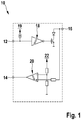
- Fig. 1 shows a block diagram of an exemplary first interface between a controller and a bus line.
- the interface 10 has an input terminal 12 and an output terminal 14, which are connected to the (not shown) controller of the on-board control unit. Via a bus line connection 16, a bus power (not shown) is connected to the interface 10.
- the interface 10 may additionally comprise a power supply terminal and / or a ground terminal, which will not be discussed here.
- an input signal output from the controller of the controller is transmitted to the interface 10.
- an output signal output from the interface 10 is transferable to the controller of the controller.
- the controller of the controller can be connected via a first line to the input terminal 12 and via a second line to the output terminal 14.
- a component of an on-board controller such as a controller is usually designed only for receiving and transmitting signals with a comparatively low voltage level.
- the signals transmitted between the interface 10 and the connected controller therefore often have a comparatively low voltage level.
- signals with such a low voltage level are not reliable and can be transmitted via the bus line with short-circuit protection.
- the interface 10 therefore comprises a transmission device 18 connected to a power supply 19, which is designed, taking into account an input signal received at the input connection 12, to receive a (corresponding) bus signal with a higher voltage level via the bus connection 16 to send out.
- the interface 10 has a receiving device 20, which is coupled to a battery 22.
- the receiving device 20 is designed to emit an output signal having the lower voltage level via the output terminal 14, taking into account a bus signal having a comparatively high voltage level received at the bus line 16.
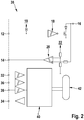
- Fig. 2 shows a block diagram of a second exemplary interface between a controller and a bus line.
- the interface 30 has the components 12 to 22 already described. However, the interface 30 is connected in addition to the terminals 12 and 14 via a fast data connection device with the controller of the vehicle's control unit. For this purpose, the interface 30 comprises four further terminals 32 to 38. Via the signal input terminal 32, high-clocked signals are transmitted from the controller to the interface 30. Accordingly, high-clocked signals can be output from the interface 30 to the controller via the signal output terminal 34. On the operation of the clock terminal 36 and the assignment terminal 38 will not be discussed here.
- a logic unit 40 of the interface 30 is coupled to the terminals 32 to 38.
- the control device 40 is designed in accordance with the received high-clocked signals, at least one further signal processing device 42 of the interface 30 to control. Likewise, information output by the at least one further signal processing device 42 can be transmitted as high-clocked signals from the control device 40 via the signal output port 34.
- the interface 30 can thus perform additional functions in addition to the transmission and reception of bus signals.
- the invention provides a signal transmission device for signal transmission between a vehicle component and a bus line having the features of claim 1 and a vehicle component having the features of claim 9.
- the present invention is based on the recognition that the functionality of the signal transmission device, the driving component connection and / or the bus line connection can be increased by the control device is designed to the predetermined bus code to the input signal and / or to determine a predetermined level change at the bus line connection and to control the transmission device accordingly. Due to the increased functionality of the signal transmission device, the driving component connection and / or the bus line connection, at least one further connection can be replaced. In this way, a minimum size of the signal transmission device can be reduced.
- the signal transmitting device and the cooperating vehicle component are implemented as separate units, such as separate integrated circuits (ICs), fewer wires / cables are needed between the signal transmitting device and the vehicle component.
- the control device is adapted to output the bus signal by the transmission device by providing the input signal and / or the transmission signal. Activate signal to the transmission device.
- the control device is thus able to detect, with input signals received at the drive component connection, for example at a controller connection, whether the input signal or a corresponding input signal Information about the bus line to be sent. Likewise, the control device can detect whether a corresponding information about the state of the bus line is to be output to the microcontroller.
- the drive component connection of the signal transmission device is also usable for receiving input signals which do not relate to information and / or function instructions to be sent via the bus line.
- the drive component port may be used to receive information and / or control signals directed directly to the controller.
- the control device may be designed to output a processing signal to another signal processing device taking into account the input signal without the predetermined bus code.
- the driving component connection can also be used to output data, information and / or function instructions to the at least one further internal and / or external signal processing device. It is thus no longer necessary that the signal transmission device has a further connection for receiving the data, information and / or function instructions to the at least one further signal processing device.
- control device is designed to determine the predetermined bus code at a high-clocked input signal, and, if the predetermined bus code is determined at the high-clocked input signal, taking into account the high-clocked input signal to output a low-clocked transmission signal to the transmission device.
- a connection for receiving a high-clocked signal can also be used as the drive component connection. This extends the application possibilities for the present invention.
- the signal transmission device can be designed as an MSC interface (micro-second channel interface).
- MSC interface micro-second channel interface
- the control device can be designed to control the transmission device for a predetermined first time interval into an inactive mode, in which the outputting of the Bus signal is prevented by the transmission device. This ensures that the reception of a signal on the bus line connection is not disturbed by the outputting of the bus signal by the transmission device. Thus, the reception characteristics of the bus line terminal can be improved.
- the signal transmission device comprises a receiving device, which is designed, taking into account a signal received at the bus line terminal with the second voltage level, an output signal with the first voltage level via the driving component connection to the vehicle component, for example to the controller, issue.
- the signal transmission device is therefore also designed to output information relating to a signal received at the bus line connection to the vehicle component.
- the drive component connection is designed as a bidirectional connection between the vehicle component and the signal transmission device. The drive component connection thus fulfills the functions of a transmission connection and a reception connection. In this way, the number of required connections of the signal transmission device can be further reduced. This allows a more advantageous design of the signal transmission device with an additionally reduced minimum size.
- control device is additionally designed to determine the predetermined level change at the driving component connection, and, if the predetermined level change is determined at the driving component connection, the receiving device for a predetermined second time interval in an inactive Mode in which the outputting of the output signal by the receiving means is inhibited. In this way it is ensured that during the transmission process no interference occurs through the active receiving device. This ensures a more advantageous use of the designed as a bidirectional connection driving components connection.
- control device may additionally be designed to output a low-clocked signal to the vehicle component, taking into account a high-clocked receive signal output by the receiver device.
- the low-clocked signal can then be output via a low-clocked data connection to the vehicle component.
- the vehicle component is designed as a control unit, as a diagnostic device and / or as a measuring device.
- the signal transmission devices described below are designed for signal transmission, data transmission, information transmission and / or function instruction transmission between a vehicle component and a bus line.
- the vehicle component can be, for example, a control device, advantageously with a controller. Under a signal transmission, data transmission, information transmission and / or function instruction transmission Thus, a transmission between the controller of the vehicle component and the signal transmission device can be understood between the vehicle component and a signal transmission device.
- the embodiments described herein are also applicable to other embodiments of a vehicle component.
- the vehicle component may be a measuring device, a diagnostic device and / or a monitoring device with which a physical variable and / or a state of at least one component of a vehicle can be detected.
- a described signal transmission device may be a subunit of the vehicle component.
- the signal transmission device can be referred to as an interface, as a transmitter / receiver and / or as a physical connection (physical layer) of the vehicle component to the bus line.
- Particularly advantageous is a described signal transmission device in an embodiment of the signal transmission device as a separate from the vehicle component compact unit, which is connected via at least one connecting device, such as a cable and / or a line with the vehicle component.
- IC integrated circuits
- the signal transmission device can be made smaller. Even lines between the vehicle component and the signal transmission device can be saved in this way.
- the bus line may be a K line, preferably in accordance with ISO-9141. Other known bus lines can also be used with the signal transmission device.
- a signal transmission device described below may be connected via the signal transmission device and the bus line with at least one further component of the vehicle, for example with at least one control device and / or a test device.
- the vehicle component is designed such that the vehicle component can communicate with the at least one further vehicle-specific and / or vehicle-external component via the signal transmission device and the bus line.
- the vehicle component and the bus line may be components of a Steuerund / or Be diagnostic system.
- the application examples enumerated here for use of the signal transmission device are only to be understood as examples.
- the described signal transmission devices are applicable in the known transceiver systems.
- a K-line can be used for communication of the vehicle component and a test device in a workshop.
- the signal transmission device is not limited to such use. It should be noted here that the signal transmission device or the bus line connection can be formed such that a known bus line is connected to the bus line connection for forwarding a signal output by the signal transmission device via the bus line connection and / or for providing a signal can be coupled to the bus line connection.
- Fig. 3 shows a block diagram of a first embodiment of the signal transmission device.
- the signal transmission device 50 is connected via a device connection 52 to the vehicle component, which is configured by way of example as a control device 53.
- the signal transmission device 50 is coupled to a (not outlined) controller of the controller 53.
- a controller or a controller of the control device 53 can also be understood by the control device 53.
- the usability of the signal transmission device 50 described below is not limited to a vehicle component designed as a control unit 53.
- the signal transmission device 50 additionally comprises a bus line connection 54, to which the bus line 55 can be coupled.
- the control device 53 can be coupled to the device connection 52 such that an input signal output by the control device 53 can be forwarded to the device connection 52 at a first voltage level.
- the control unit 53 can be connected to the device connection 52, for example via a line.
- the input signal may be, for example, a function instruction, an information via a logic state of the controller 53 and / or via a determined by the controller 53 size.
- the first voltage level of the input signal provided to the device port 52 may be less than 5 volts.
- the first voltage level of the input signal is between 0 volts and 3 volts.
- the input signal with such a first voltage level is thus hardly reliable and short-circuit-proof via the bus line 55 forwarded.
- the use of the signal transmission device 50 is thus particularly advantageous in the case of a control unit 53 which is not designed to transmit and / or receive signals which can be forwarded via the bus line 55.
- the signal transmission device 50 comprises a transmission device 56.
- the transmission device 56 is designed, in consideration of an input signal received at the device connection 52 with the first voltage level, to supply a bus signal with a second, higher voltage level to the bus line. Output port 54.
- the bus signal output to the bus line connection 54 can then be forwarded via the bus line 55 coupled to the bus line connection 54.
- the second voltage level of the bus signal output by the signal transmission device 50 is above the first voltage level of the input signal sent by the controller 53.
- the second voltage level of the bus signal may be greater than 5V.
- the second voltage level of the bus signal is in a range between 6V to 18V.
- Such a bus signal can be relayed reliably and with short-circuit protection via the bus line.
- the transmission device 56 is coupled to a control device 58 of the signal transmission device 50 such that the provision of the bus signal to the bus connection 54 by the transmission device 56 by means of the control device 58 is controllable.
- the control device 58 may be, for example, a logic device.
- the controller 58 is additionally adapted to a predetermined level change at the bus line connection 54 to determine.
- the transmission device 56 is therefore suitable for controlling the provision of the bus signal to the bus line connection 54 taking into account the determined predetermined level change.
- the control device 58 is designed, if the predetermined level change is determined to the bus line connection 54, to control the transmission device 56 to an inactive mode in which a signal forwarding by the transmission device 56 is inhibited. This can be realized via a suitable coupling of the control device 58 to the transmission device 56.
- control device 58 By means of the control device 58, it can be prevented that the transmission device 56 transmits a bus signal via the bus line connection 54 at a time at which a level change occurs at the bus line connection 54.
- the bus line connection 54 can thus be used exclusively for receiving a signal when the predetermined level change is detected.
- the reception characteristics of the bus line connection 54 are thus improved. This extends the multifunctionality of the bus line connection 54, which can thus also be used for reliable receiving of signals.
- the control device 58 is preferably designed to determine a level change from an inactive level to an active-drive level at the bus line connection 54 as a predetermined level change. In this case, secure detection of a signal reception by the bus line terminal 54 is ensured.
- controller 58 may be configured, if the level change from the inactive level to the active-driven level is detected, to disable the transmitter 56 for a predetermined first time interval. In this way, it is ensured that the receipt of a signal to the bus line connection 54 during the first time interval is not disturbed, even if an intermediate signal is received in the meantime.
- the signal transmission device 50 also comprises a reception device 60.
- the reception device 60 is designed to output an output signal having the first voltage level, taking into account a signal having a second voltage level received at the bus line connection 54.
- the signal transmission device 50 is thus additionally usable, in order to output to the control unit 53 an output signal which can be processed by the control unit 53 for a signal provided by the bus line 55 to the bus line connection 54.
- the output signal may include, for example, information about a logical state of the bus line, a logical state of another component of a vehicle and / or a function instruction.
- the signal transmission device 50 can also be designed to check by means of the receiving device 60 whether a bus signal output via the bus line connection 54 corresponds to an input signal received at the device connection 52 and / or ob the data transmitted via the bus line 55 correspond to the data of the control device 53 received at the device port 52.
- the receiving device 60 is coupled to the device port 52 so that the output signal via the device port 52 to the controller 53 can be output.
- the device port 52 is thus designed as a bidirectional connection.
- the device connection 52 of the signal transmission device 50 can fulfill the functions of a reception connection and a transmission connection. This is advantageous because attaching a receive connection and a send connection to an interface requires a comparatively large minimum extension of the interface. Often, the total number of ports of an interface is the significant obstacle to minimizing the interface.
- the bidirectional design of the device port 52 thus helps to reduce the total number of ports 52 and 54 of the signal transmission device 50. By reducing the terminals 52 and 54, a smaller configuration of the signal transmission device 50 becomes possible. Thus, the formation of the device connection 52 as a bidirectional connection simplifies the installation of the signal transmission device 50 on a vehicle.
- the signal transmission device 50 is additionally designed to prevent simultaneous transmission and reception via the device port 52, ie a dead-lock. This is at a Using the signal transmission device 50 as a bidirectional single-wire interface between the controller 53 and the bus line 55 advantageous.
- the advantageous embodiment of the signal transmission device 50 can be realized by the control device 58 is additionally designed to determine a predetermined level change at the device port 52, and to control the receiving device 60 so that the emission of the output signal via the Device port 52 is prevented by the receiving device 60.
- the control device 58 controls the receiving device 60, provided that the predetermined level change is detected at the device port 52, into an inactive mode in which a signal forwarding by the receiving device 60 is inhibited.
- the receiving device 60 is thus not configured in the inactive mode to output a corresponding output signal with the first voltage level for a signal received at the bus line connection 54 with the second voltage level.
- a predetermined level change at the device port 52 for example, a level change from an inactive level to an active-geared level at the device port 52 can be determined. This ensures reliable detection of a signal reception by the device connection 52.
- the control device 58 may be designed to deactivate the receiving device 60 for a predetermined second time interval if the predetermined level change at the device port 52 is determined. Thus, the receipt of the input signal at the signal terminal 52 is not disturbed even in the meantime receiving a zero signal during the second time interval.
- the second time interval may be exactly as long as the first time interval. Alternatively, one of the two time intervals may be set longer. This is advantageous in a specialization of the signal transmission device 50 for receiving important signals or for transmitting important bus signals,
- a logic for the signal transmission device 50 can be realized, in which the device port 52 is actively operated only when transmitting active data to the control unit 53 via the bus line 55 by means of an external transmitter.
- the signal transmission device 50 After detecting the predetermined level change to the bus line connection 54 while the transmission device 56 is deactivated.
- the signal transmission device 50 then exclusively fulfills the function of a receiver which transmits data from the bus line 55 to the control unit 53 via the device connection 52. If the control unit 53 outputs an input signal to the device connection 52 during the first time interval, no corresponding output of a bus signal is output to the bus line.
- the controller 53 can thus easily provide data to the bidirectional device port 52. However, the provided data is not transmitted to the bus line 55.
- the reception device 60 is deactivated for the second time interval.
- the signal transmission device 50 thus transitions into the transmitter mode for the second time interval.
- the signal transmission device 50 functions exclusively as a transmitter during the second time interval and transmits the data / information / function instructions received at the device port 52 via the bus line 55.
- no output signal is output to the controller 53 during the second time interval. If another bus subscriber sends data to the control unit 53 during the second time interval, then no immediate forwarding of the data to the control unit 53 takes place.
- the receiver mode and / or the transmitter mode of the signal transmission device 50 can be terminated via a suitable reset signal, for example by means of an undervoltage.
- a suitable reset signal for example by means of an undervoltage.
- a second branch point 72 is formed between the diode 70 and the bus line terminal 54.
- the first signal path with the transmission device 56 is arranged parallel to a second signal path with the reception device 60.
- a first resistor 74 of the receiving device 60 is connected. Via the first resistor 74, the second branch point 72 and the bus line connection 54 are connected to a first signal input of a receiving unit 76 of the receiving device 60. A second signal input of the receiving unit 76 is connected via a third branch point 78 to a line which connects a ground 80 to a battery terminal 82. Between the ground 80 and the third branch point 78, a second resistor 84 is arranged. A third resistor 86 connects the third branch point 78 to the battery terminal 82.
- a transistor 88 is arranged between a signal output of the receiving unit 76 and the first branch point 62.
- the control device 58 can be arranged on the receiving device 60 that a signal transmission between the receiving unit 76 and the transistor 88 is inhibited, provided that the predetermined level change is determined to the device port 52.
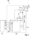
- Fig. 4 shows a block diagram of a second embodiment of the signal transmission device.
- the schematically represented signal transmission device 100 is connected via a fast data connection device to a vehicle component (not shown).
- vehicle component is formed in the described example as a control unit 53.
- the embodiment described here is not limited to a design of the vehicle component as the control unit 53.
- the fast data connection device is understood as meaning, for example, a connection device for a high-clocked data transmission. Preferably, at least 100 to 1000 values per ms can be transmitted via the fast data connection device.
- An example of a suitable fast data connection device is, for example, an MSC connection (micro-second channel). This is advantageous because an MSC connection is often used for vehicle component communication.
- the embodiment described herein is not limited to a fast data connection device designed as an MSC connection.
- control unit 53 is preferably able to control the signal transmission device 100 (interface) between the control unit 53 and the bus line 55, which is designed as an ASIC, for example, quickly and sufficiently via an MSC connection.
- the signal transmission device 100 has four ports 102 to 108.
- a signal input terminal 102 (data input terminal, data-in) is configured to receive an input signal output from the controller 53.
- a signal output terminal 104 (data output terminal, data-out) is designed so that a for the control unit 53 processable output signal via the signal output terminal 104 to the control unit 53 is forwarded.
- the signals exchanged between the controller 53 and the ports 102 and 104 may include data, information regarding a state of the controller 53, and / or a functional instruction. On the operation of a clock terminal 106 (Clock) and an assignment terminal 108 (enable) will not be discussed in more detail here.
- a bus line 55 can be coupled to the signal transmission device 100.
- the signal transmission device 100 is not limited to cooperating with a particular type of bus line 55.
- the signal transmission device 100 comprises a transmission device 56 and a reception device 60, which are connected to the bus line connection 54 via a branch point 72.
- the devices 56 and 60 have the already described components 66 to 70 and 74 to 86.
- the signal transmission between the control unit 53 and the two terminals 102 and 104 may be clocked significantly higher than a signal transmission between the signal transmission device 100 and the bus line 55 via the bus line connection 54.
- the bus line 55 has a data transmission rate of approximately 10 kbit / s.
- the interface between the control unit 53 and the bus line 55 ASIC
- This requirement consists of 16 bits for command and data per write-read cycle, 2-bit pause between two read / write cycles and a maximum of 10% jitter.
- the requirement for control devices 53 specified in the ISO 9141 standard is also met by the 10% jitter.
- the temporal position of each bit edge thus shifts by at most 20% of the bit time compared with the time position calculated from the baud rate.
- the signal transmission device 100 comprises a control device 110, which is designed to control at least one signal processing device 112, taking into account an input signal received at the signal input connection 102.
- the activation of the at least one signal processing device 112 can also be understood as the provision of data, information about a state of the control device 53 and / or a function instruction.
- the control device 110 is designed as a logic device.
- the signal processing device 112 may be an internal device of the signal transmission device 100. However, the signal transmission device 100 described herein is not limited to such a configuration. As an alternative or as a supplement, the control device 110 can also be designed to control an external signal processing device 112. The control device 110 can be connected to each of the ports 102 to 104 via a respective computer unit 114 to 120.
- the signal transmission device 100 is additionally designed to realize a communication between the control device 53 and the bus line 55 via the connections 102 and 104.
- the control device 110 is designed to determine a predetermined bus code on the input signal, which is provided at the signal input terminal 102.
- the control device 110 can detect whether the input signal provided to the signal input terminal 102 of a message which is to be forwarded via the bus line 55, such as data, an information about a state of the controller 53 and / or a functional instruction corresponds.
- the control device 110 recognizes an input signal specific to the at least one signal processing device 112 and actuates the signal processing device 112 accordingly.
- the control unit 53 is designed to mark messages for forwarding via the bus line 55 with the bus code.
- the bus code is a frequency that is specific to the controller bus line communication is fixed.
- the bus code may also be a lack of a code relating to the input signals that are not intended to be forwarded over the bus 55.
- the control device 110 is adapted to the output of a bus signal corresponding to the input signal via the bus line 55 by the transmission device 56th to prevent.
- the control device 110 is designed to output the input signal or a corresponding transmission signal to the transmission device 56 only after determining an input signal with the predetermined bus code. The control device 110 can thus distinguish messages which are to be forwarded via the bus line 55 from other signals received at the signal input connection 102 and control the transmission device 56 accordingly.
- control device 110 is advantageously designed to output a (corresponding) processing signal to the associated at least one signal processing device 112, taking into account the received input signal.
- the signal input connection 102 can fulfill the functions of a first connection of an interface between a control device 53 and a bus line 55 and a second connection between a fast data connection and at least one signal processing device 112. Due to the multi-functionality of the signal input terminal 102, the number of terminals required on the signal transmission device 100 can be reduced. The minimum size of the signal transmission device 100 can also be reduced in this way.
- the control device 110 is designed to output a low-clocked transmission signal to the transmission device 56.
- the transmission device 56 can in this case by means of already described components 66 to 70 output the bus signal to the bus line connection 54 for forwarding via the bus line 55.
- the control device 110 when the control device 110 is additionally designed, taking into account one of the receiving device 60 output low-clocked receive signal, a high-clocked signal to the Issue controller 53 via the signal output port 104.
- the signal output 104 fulfills the functions of a first connection of an interface between a control unit 53 and a bus line 55 and a second connection between the fast data connection and the signal processing device 112. This multifunctionality of the signal output connection 104 reduces the minimum size of the signal transmission device 100 and facilitates their installation in a vehicle.
- an overall terminal may perform the functions of the signal input terminal 102 and the signal output terminal 104 in common.
Landscapes
- Engineering & Computer Science (AREA)
- Computer Networks & Wireless Communication (AREA)
- Signal Processing (AREA)
- Small-Scale Networks (AREA)
- Dc Digital Transmission (AREA)
- Bidirectional Digital Transmission (AREA)
Claims (9)
- Dispositif de transmission de signal (50 ; 100) pour une transmission de signal entre un composant de véhicule (53) et une ligne de bus (55), comprenant :une borne de composant de véhicule (52 ; 102) à laquelle le composant de véhicule (53) peut être connecté de telle sorte que le composant de véhicule (53) peut appliquer à la borne de composant de véhicule (52 ; 102) un signal d'entrée ayant un premier niveau de tension ;un appareil de transmission (56) qui est conçu pour délivrer, en fonction du signal d'entrée appliqué, un signal de bus ayant un deuxième niveau de tension ne correspondant pas au premier niveau de tension ; etune borne de ligne de bus (54) à laquelle la ligne de bus (55) peut être connectée de telle sorte que le signal de bus délivré par l'appareil de transmission (56) peut être retransmis par le biais de la ligne de bus (55) ;un appareil de commande (58 ; 110) qui est conçu pour déterminer un code de bus sur le signal d'entrée et un changement de niveau sur la borne de ligne de bus (54) et, en tenant compte du code de bus déterminé sur le signal d'entrée et du changement de niveau déterminé sur la borne de ligne de bus (54), commander la délivrance du signal de bus par l'appareil de transmission (56) ;un appareil de réception (60) qui est conçu pour délivrer au composant de véhicule (53), par le biais de la borne de composant de véhicule (52), un signal de sortie ayant le premier niveau de tension en tenant compte d'un signal reçu sur la borne de ligne de bus (54) ayant le deuxième niveau de tension,caractérisé en ce quele dispositif de transmission de signal (50 ; 100) est réalisé sous la forme d'une interface unifilaire bidirectionnelle ;l'appareil de réception (60) est connecté à la borne de composant de véhicule (52) de telle sorte que le signal de sortie peut être délivré au composant de véhicule (53) par le biais de la borne de composant de véhicule (52),la borne de composant de véhicule (52 ; 102) est réalisée sous la forme d'une borne unifilaire bidirectionnelleet le dispositif de transmission de signal (100) est conçu pour empêcher une émission et une réception simultanées par le biais de la borne de composant de véhicule (52 ; 102),en ce que l'appareil de commande (58 ; 110) est conçu pour déterminer un changement de niveau prédéfini sur la borne de composant de véhicule (52 ; 102) et commander l'appareil de réception (60) de telle sorte que la délivrance du signal de sortie par le biais de la borne de composant de véhicule (52 ; 102) est inhibée lorsque le changement de niveau prédéfini est déterminé.
- Dispositif de transmission de signal (100) selon la revendication 1, l'appareil de commande (110) étant conçu pour, sous réserve que le code de bus soit déterminé sur le signal d'entrée, activer la délivrance du signal de bus par l'appareil de transmission (56) en fournissant le signal d'entrée et/ou le signal de transmission à l'appareil de transmission (56).
- Dispositif de transmission de signal (100) selon la revendication 1 ou 2, l'appareil de commande (110) étant conçu pour, sous réserve qu'un signal d'entrée sans code de bus soit déterminé, délivrer un signal de traitement à un appareil de traitement de signal (112) supplémentaire en tenant compte du signal d'entrée sans code de bus.
- Dispositif de transmission de signal (100) selon l'une des revendications précédentes, l'appareil de commande (110) étant conçu pour déterminer le code de bus sur un signal d'entrée à rythme élevé et, sous réserve que le code de bus soit déterminé sur le signal d'entrée à rythme élevé, délivrer un signal de transmission à rythme lent à l'appareil de transmission (56) en tenant compte du signal d'entrée à rythme élevé.
- Dispositif de transmission de signal (100) selon l'une des revendications précédentes, le dispositif de transmission de signal (100) étant réalisé sous la forme d'une interface MSC (micro-canal conjugué).
- Dispositif de transmission de signal (50) selon l'une des revendications précédentes, l'appareil de commande (58) étant conçu pour, sous réserve que le changement de niveau soit déterminé sur la borne de ligne de bus, commander l'appareil de transmission (56) pendant un premier intervalle de temps prédéfini dans un mode inactif dans lequel la délivrance du signal de bus par l'appareil de transmission (56) est inhibée.
- Dispositif de transmission de signal (50) selon l'une des revendications précédentes, l'appareil de commande (58) étant en outre conçu pour déterminer le changement de niveau sur la borne de composant de véhicule (52) et, sous réserve que le changement de niveau soit déterminé sur la borne de composant de véhicule (52), commander l'appareil de réception (60) pendant un deuxième intervalle de temps prédéfini dans un mode inactif dans lequel la délivrance du signal de sortie par l'appareil de réception (60) est inhibée.
- Composant de véhicule (53) comprenant un dispositif de transmission de signal (50 ; 100) selon l'une des revendications précédentes.
- Composant de véhicule (53) selon la revendication 8, le composant de véhicule (53) étant réalisé sous la forme d'un contrôleur (53), d'un appareil de diagnostic et/ou d'un appareil de mesure.
Applications Claiming Priority (2)
| Application Number | Priority Date | Filing Date | Title |
|---|---|---|---|
| DE102009027471A DE102009027471A1 (de) | 2009-07-06 | 2009-07-06 | Signalübertragungsvorrichtung und Fahrzeugkomponente |
| PCT/EP2010/057024 WO2011003666A1 (fr) | 2009-07-06 | 2010-05-21 | Dispositif de transmission de signaux et composant de véhicule |
Publications (2)
| Publication Number | Publication Date |
|---|---|
| EP2452467A1 EP2452467A1 (fr) | 2012-05-16 |
| EP2452467B1 true EP2452467B1 (fr) | 2017-07-12 |
Family
ID=42307907
Family Applications (1)
| Application Number | Title | Priority Date | Filing Date |
|---|---|---|---|
| EP10721154.2A Not-in-force EP2452467B1 (fr) | 2009-07-06 | 2010-05-21 | Dispositif de transmission de signaux et composant de véhicule |
Country Status (5)
| Country | Link |
|---|---|
| EP (1) | EP2452467B1 (fr) |
| CN (1) | CN102474437B (fr) |
| DE (1) | DE102009027471A1 (fr) |
| TW (1) | TWI521926B (fr) |
| WO (1) | WO2011003666A1 (fr) |
Families Citing this family (2)
| Publication number | Priority date | Publication date | Assignee | Title |
|---|---|---|---|---|
| DE102011082509B4 (de) * | 2011-09-12 | 2024-07-11 | Vitesco Technologies GmbH | Schaltungsanordnung zur Vermeidung von Kollisionen beim Datentransfer |
| DE102012201596A1 (de) * | 2012-02-03 | 2013-08-08 | Robert Bosch Gmbh | Empfangsanordnung für ein Steuergerät in einem Fahrzeug und Verfahren zum Erzeugen eines Synchronisationspulses |
Family Cites Families (4)
| Publication number | Priority date | Publication date | Assignee | Title |
|---|---|---|---|---|
| JP3829679B2 (ja) * | 2001-10-09 | 2006-10-04 | 株式会社デンソー | 通信制御装置 |
| DE10225578A1 (de) * | 2002-06-10 | 2003-12-18 | Philips Intellectual Property | Verfahren und Chipeinheit zum Ansprechen und/oder Aktivieren eines Teilnehmers |
| DE10261386A1 (de) * | 2002-12-30 | 2004-07-08 | Robert Bosch Gmbh | Vorrichtung für einen Leitungsabschluss von Zweidraht-Leitungen |
| US7671628B2 (en) * | 2006-01-13 | 2010-03-02 | Motorola, Inc. | Bus interface and method for conveying multi-level communication signals between a communication bus and a device coupled to a communication bus |
-
2009
- 2009-07-06 DE DE102009027471A patent/DE102009027471A1/de not_active Withdrawn
-
2010
- 2010-05-21 WO PCT/EP2010/057024 patent/WO2011003666A1/fr not_active Ceased
- 2010-05-21 CN CN201080030453.9A patent/CN102474437B/zh active Active
- 2010-05-21 EP EP10721154.2A patent/EP2452467B1/fr not_active Not-in-force
- 2010-07-05 TW TW099121977A patent/TWI521926B/zh not_active IP Right Cessation
Non-Patent Citations (1)
| Title |
|---|
| None * |
Also Published As
| Publication number | Publication date |
|---|---|
| DE102009027471A1 (de) | 2011-01-13 |
| TWI521926B (zh) | 2016-02-11 |
| WO2011003666A1 (fr) | 2011-01-13 |
| CN102474437B (zh) | 2016-03-16 |
| EP2452467A1 (fr) | 2012-05-16 |
| CN102474437A (zh) | 2012-05-23 |
| TW201105072A (en) | 2011-02-01 |
Similar Documents
| Publication | Publication Date | Title |
|---|---|---|
| EP3656096B1 (fr) | Dispositif d'envoi et de réception pour système de bus can et procédé de détection d'un court-circuit avec un dispositif d'envoi et de réception can | |
| EP3114801B1 (fr) | Station d'abonné pour un système de bus et procédé de réduction d'émissions liées à une ligne dans un système de bus | |
| DE19616293A1 (de) | Bussystem für die Übertragung von Nachrichten | |
| EP3222009B1 (fr) | Station d'abonné pour un système de bus et procédé servant à régler une synchronisation d'un signal d'émission pour un système de bus | |
| DE19922171B4 (de) | Kommunikationssystem mit einem Kommunikationsbus | |
| EP3977683B1 (fr) | Dispositif pour une station d'abonné d'un système de bus série et procédé de communication dans un système de bus série | |
| EP3900271A1 (fr) | Dispositif pour une station participante d'un système de bus série et procédé de communication dans un système de bus série | |
| DE10134584B4 (de) | Bussystem und Verfahren zum Austausch von Daten | |
| EP1410577B1 (fr) | Elements reseau destines a un reseau optique ayant une fonction de securite, en particulier a un reseau optique a topologie annulaire | |
| EP3108603A1 (fr) | Poste utilisateur pour système de bus et procédé d'augmentation du débit de données d'un système de bus | |
| EP2452467B1 (fr) | Dispositif de transmission de signaux et composant de véhicule | |
| DE102020128430B4 (de) | Feldbussystem mit umschaltbarer slew-rate | |
| EP2012469B1 (fr) | Procédé de fonctionnement d'un quasi-bus pour un système de protection des personnes, appareil de commande destiné à la commande d'un système de protection des personnes et dispositif de transmission de données de capteurs vers un appareil de commande destiné à la commande d'un système de protection des personnes par au moins un quasi-bus | |
| EP1227406B1 (fr) | Dispositif d'émission et de réception avec des moyens de gestion d'erreur | |
| EP2534582B1 (fr) | Circuit d'un genre nouveau et procédé de communication par le biais d'une ligne unique | |
| EP3665869A1 (fr) | Dispositif d'émission/réception pour systeme de bus et procédé de réduction de la tendance à osciller entre differents états binaires | |
| EP1787206B1 (fr) | Dispositif de transmission de signal | |
| WO2017046032A1 (fr) | Circuit de verrouillage et procédé de blocage d'une ligne de données | |
| EP2067668A1 (fr) | Procédé et dispositif destinés à l'étude du risque d'une évaluation de signaux relatifs à la sécurité pour un véhicule automobile | |
| EP4131848A1 (fr) | Procédé et circuit permettant de faire fonctionner un réseau ou une section de réseau | |
| DE102017110151B3 (de) | Vorrichtung und Verfahren zur Plausibilisierung von Referenzströmen in einer Mehrpegel-PSI5-Datenbusschnittstelle | |
| DE102017223417B4 (de) | Verfahren zum Selbsttest, Datenbusanordnung und Verwendung | |
| DE102012201669B4 (de) | Verfahren und Kommunikationscontroller zur Datenübertragung zwischen zwei mittels Übertragungsstrecken verbundenen Datenverarbeitungseinheiten | |
| DE60313592T2 (de) | Teilen einer synchronen kommunikationsschnittstelle zum kommunizieren mit mehreren vorrichtungen | |
| DE102023104918B3 (de) | Integrierte Schaltung mit umschaltbaren Anschlussmöglichkeiten |
Legal Events
| Date | Code | Title | Description |
|---|---|---|---|
| PUAI | Public reference made under article 153(3) epc to a published international application that has entered the european phase |
Free format text: ORIGINAL CODE: 0009012 |
|
| 17P | Request for examination filed |
Effective date: 20120206 |
|
| AK | Designated contracting states |
Kind code of ref document: A1 Designated state(s): AL AT BE BG CH CY CZ DE DK EE ES FI FR GB GR HR HU IE IS IT LI LT LU LV MC MK MT NL NO PL PT RO SE SI SK SM TR |
|
| DAX | Request for extension of the european patent (deleted) | ||
| 17Q | First examination report despatched |
Effective date: 20150311 |
|
| GRAP | Despatch of communication of intention to grant a patent |
Free format text: ORIGINAL CODE: EPIDOSNIGR1 |
|
| INTG | Intention to grant announced |
Effective date: 20170210 |
|
| GRAS | Grant fee paid |
Free format text: ORIGINAL CODE: EPIDOSNIGR3 |
|
| GRAA | (expected) grant |
Free format text: ORIGINAL CODE: 0009210 |
|
| AK | Designated contracting states |
Kind code of ref document: B1 Designated state(s): AL AT BE BG CH CY CZ DE DK EE ES FI FR GB GR HR HU IE IS IT LI LT LU LV MC MK MT NL NO PL PT RO SE SI SK SM TR |
|
| REG | Reference to a national code |
Ref country code: GB Ref legal event code: FG4D Free format text: NOT ENGLISH |
|
| REG | Reference to a national code |
Ref country code: CH Ref legal event code: EP |
|
| REG | Reference to a national code |
Ref country code: AT Ref legal event code: REF Ref document number: 909272 Country of ref document: AT Kind code of ref document: T Effective date: 20170715 |
|
| REG | Reference to a national code |
Ref country code: IE Ref legal event code: FG4D Free format text: LANGUAGE OF EP DOCUMENT: GERMAN |
|
| REG | Reference to a national code |
Ref country code: DE Ref legal event code: R096 Ref document number: 502010013849 Country of ref document: DE |
|
| REG | Reference to a national code |
Ref country code: NL Ref legal event code: MP Effective date: 20170712 |
|
| REG | Reference to a national code |
Ref country code: LT Ref legal event code: MG4D |
|
| PG25 | Lapsed in a contracting state [announced via postgrant information from national office to epo] |
Ref country code: NO Free format text: LAPSE BECAUSE OF FAILURE TO SUBMIT A TRANSLATION OF THE DESCRIPTION OR TO PAY THE FEE WITHIN THE PRESCRIBED TIME-LIMIT Effective date: 20171012 Ref country code: SE Free format text: LAPSE BECAUSE OF FAILURE TO SUBMIT A TRANSLATION OF THE DESCRIPTION OR TO PAY THE FEE WITHIN THE PRESCRIBED TIME-LIMIT Effective date: 20170712 Ref country code: NL Free format text: LAPSE BECAUSE OF FAILURE TO SUBMIT A TRANSLATION OF THE DESCRIPTION OR TO PAY THE FEE WITHIN THE PRESCRIBED TIME-LIMIT Effective date: 20170712 Ref country code: FI Free format text: LAPSE BECAUSE OF FAILURE TO SUBMIT A TRANSLATION OF THE DESCRIPTION OR TO PAY THE FEE WITHIN THE PRESCRIBED TIME-LIMIT Effective date: 20170712 Ref country code: HR Free format text: LAPSE BECAUSE OF FAILURE TO SUBMIT A TRANSLATION OF THE DESCRIPTION OR TO PAY THE FEE WITHIN THE PRESCRIBED TIME-LIMIT Effective date: 20170712 Ref country code: LT Free format text: LAPSE BECAUSE OF FAILURE TO SUBMIT A TRANSLATION OF THE DESCRIPTION OR TO PAY THE FEE WITHIN THE PRESCRIBED TIME-LIMIT Effective date: 20170712 |
|
| PG25 | Lapsed in a contracting state [announced via postgrant information from national office to epo] |
Ref country code: LV Free format text: LAPSE BECAUSE OF FAILURE TO SUBMIT A TRANSLATION OF THE DESCRIPTION OR TO PAY THE FEE WITHIN THE PRESCRIBED TIME-LIMIT Effective date: 20170712 Ref country code: IS Free format text: LAPSE BECAUSE OF FAILURE TO SUBMIT A TRANSLATION OF THE DESCRIPTION OR TO PAY THE FEE WITHIN THE PRESCRIBED TIME-LIMIT Effective date: 20171112 Ref country code: ES Free format text: LAPSE BECAUSE OF FAILURE TO SUBMIT A TRANSLATION OF THE DESCRIPTION OR TO PAY THE FEE WITHIN THE PRESCRIBED TIME-LIMIT Effective date: 20170712 Ref country code: GR Free format text: LAPSE BECAUSE OF FAILURE TO SUBMIT A TRANSLATION OF THE DESCRIPTION OR TO PAY THE FEE WITHIN THE PRESCRIBED TIME-LIMIT Effective date: 20171013 Ref country code: BG Free format text: LAPSE BECAUSE OF FAILURE TO SUBMIT A TRANSLATION OF THE DESCRIPTION OR TO PAY THE FEE WITHIN THE PRESCRIBED TIME-LIMIT Effective date: 20171012 Ref country code: PL Free format text: LAPSE BECAUSE OF FAILURE TO SUBMIT A TRANSLATION OF THE DESCRIPTION OR TO PAY THE FEE WITHIN THE PRESCRIBED TIME-LIMIT Effective date: 20170712 |
|
| REG | Reference to a national code |
Ref country code: DE Ref legal event code: R097 Ref document number: 502010013849 Country of ref document: DE |
|
| PG25 | Lapsed in a contracting state [announced via postgrant information from national office to epo] |
Ref country code: DK Free format text: LAPSE BECAUSE OF FAILURE TO SUBMIT A TRANSLATION OF THE DESCRIPTION OR TO PAY THE FEE WITHIN THE PRESCRIBED TIME-LIMIT Effective date: 20170712 Ref country code: RO Free format text: LAPSE BECAUSE OF FAILURE TO SUBMIT A TRANSLATION OF THE DESCRIPTION OR TO PAY THE FEE WITHIN THE PRESCRIBED TIME-LIMIT Effective date: 20170712 Ref country code: CZ Free format text: LAPSE BECAUSE OF FAILURE TO SUBMIT A TRANSLATION OF THE DESCRIPTION OR TO PAY THE FEE WITHIN THE PRESCRIBED TIME-LIMIT Effective date: 20170712 |
|
| PLBE | No opposition filed within time limit |
Free format text: ORIGINAL CODE: 0009261 |
|
| STAA | Information on the status of an ep patent application or granted ep patent |
Free format text: STATUS: NO OPPOSITION FILED WITHIN TIME LIMIT |
|
| PG25 | Lapsed in a contracting state [announced via postgrant information from national office to epo] |
Ref country code: EE Free format text: LAPSE BECAUSE OF FAILURE TO SUBMIT A TRANSLATION OF THE DESCRIPTION OR TO PAY THE FEE WITHIN THE PRESCRIBED TIME-LIMIT Effective date: 20170712 Ref country code: SM Free format text: LAPSE BECAUSE OF FAILURE TO SUBMIT A TRANSLATION OF THE DESCRIPTION OR TO PAY THE FEE WITHIN THE PRESCRIBED TIME-LIMIT Effective date: 20170712 Ref country code: IT Free format text: LAPSE BECAUSE OF FAILURE TO SUBMIT A TRANSLATION OF THE DESCRIPTION OR TO PAY THE FEE WITHIN THE PRESCRIBED TIME-LIMIT Effective date: 20170712 Ref country code: SK Free format text: LAPSE BECAUSE OF FAILURE TO SUBMIT A TRANSLATION OF THE DESCRIPTION OR TO PAY THE FEE WITHIN THE PRESCRIBED TIME-LIMIT Effective date: 20170712 |
|
| 26N | No opposition filed |
Effective date: 20180413 |
|
| PG25 | Lapsed in a contracting state [announced via postgrant information from national office to epo] |
Ref country code: SI Free format text: LAPSE BECAUSE OF FAILURE TO SUBMIT A TRANSLATION OF THE DESCRIPTION OR TO PAY THE FEE WITHIN THE PRESCRIBED TIME-LIMIT Effective date: 20170712 |
|
| PG25 | Lapsed in a contracting state [announced via postgrant information from national office to epo] |
Ref country code: MT Free format text: LAPSE BECAUSE OF FAILURE TO SUBMIT A TRANSLATION OF THE DESCRIPTION OR TO PAY THE FEE WITHIN THE PRESCRIBED TIME-LIMIT Effective date: 20170712 |
|
| REG | Reference to a national code |
Ref country code: CH Ref legal event code: PL |
|
| GBPC | Gb: european patent ceased through non-payment of renewal fee |
Effective date: 20180521 |
|
| REG | Reference to a national code |
Ref country code: BE Ref legal event code: MM Effective date: 20180531 |
|
| PG25 | Lapsed in a contracting state [announced via postgrant information from national office to epo] |
Ref country code: MC Free format text: LAPSE BECAUSE OF FAILURE TO SUBMIT A TRANSLATION OF THE DESCRIPTION OR TO PAY THE FEE WITHIN THE PRESCRIBED TIME-LIMIT Effective date: 20170712 |
|
| REG | Reference to a national code |
Ref country code: IE Ref legal event code: MM4A |
|
| PG25 | Lapsed in a contracting state [announced via postgrant information from national office to epo] |
Ref country code: LI Free format text: LAPSE BECAUSE OF NON-PAYMENT OF DUE FEES Effective date: 20180531 Ref country code: CH Free format text: LAPSE BECAUSE OF NON-PAYMENT OF DUE FEES Effective date: 20180531 |
|
| PG25 | Lapsed in a contracting state [announced via postgrant information from national office to epo] |
Ref country code: LU Free format text: LAPSE BECAUSE OF NON-PAYMENT OF DUE FEES Effective date: 20180521 |
|
| PG25 | Lapsed in a contracting state [announced via postgrant information from national office to epo] |
Ref country code: FR Free format text: LAPSE BECAUSE OF NON-PAYMENT OF DUE FEES Effective date: 20180531 Ref country code: GB Free format text: LAPSE BECAUSE OF NON-PAYMENT OF DUE FEES Effective date: 20180521 Ref country code: IE Free format text: LAPSE BECAUSE OF NON-PAYMENT OF DUE FEES Effective date: 20180521 |
|
| PG25 | Lapsed in a contracting state [announced via postgrant information from national office to epo] |
Ref country code: BE Free format text: LAPSE BECAUSE OF NON-PAYMENT OF DUE FEES Effective date: 20180531 |
|
| REG | Reference to a national code |
Ref country code: AT Ref legal event code: MM01 Ref document number: 909272 Country of ref document: AT Kind code of ref document: T Effective date: 20180521 |
|
| PG25 | Lapsed in a contracting state [announced via postgrant information from national office to epo] |
Ref country code: AT Free format text: LAPSE BECAUSE OF NON-PAYMENT OF DUE FEES Effective date: 20180521 |
|
| PG25 | Lapsed in a contracting state [announced via postgrant information from national office to epo] |
Ref country code: TR Free format text: LAPSE BECAUSE OF FAILURE TO SUBMIT A TRANSLATION OF THE DESCRIPTION OR TO PAY THE FEE WITHIN THE PRESCRIBED TIME-LIMIT Effective date: 20170712 |
|
| PG25 | Lapsed in a contracting state [announced via postgrant information from national office to epo] |
Ref country code: PT Free format text: LAPSE BECAUSE OF FAILURE TO SUBMIT A TRANSLATION OF THE DESCRIPTION OR TO PAY THE FEE WITHIN THE PRESCRIBED TIME-LIMIT Effective date: 20170712 Ref country code: HU Free format text: LAPSE BECAUSE OF FAILURE TO SUBMIT A TRANSLATION OF THE DESCRIPTION OR TO PAY THE FEE WITHIN THE PRESCRIBED TIME-LIMIT; INVALID AB INITIO Effective date: 20100521 |
|
| PG25 | Lapsed in a contracting state [announced via postgrant information from national office to epo] |
Ref country code: MK Free format text: LAPSE BECAUSE OF NON-PAYMENT OF DUE FEES Effective date: 20170712 Ref country code: CY Free format text: LAPSE BECAUSE OF FAILURE TO SUBMIT A TRANSLATION OF THE DESCRIPTION OR TO PAY THE FEE WITHIN THE PRESCRIBED TIME-LIMIT Effective date: 20170712 |
|
| PG25 | Lapsed in a contracting state [announced via postgrant information from national office to epo] |
Ref country code: AL Free format text: LAPSE BECAUSE OF FAILURE TO SUBMIT A TRANSLATION OF THE DESCRIPTION OR TO PAY THE FEE WITHIN THE PRESCRIBED TIME-LIMIT Effective date: 20170712 |
|
| PGFP | Annual fee paid to national office [announced via postgrant information from national office to epo] |
Ref country code: DE Payment date: 20240726 Year of fee payment: 15 |
|
| REG | Reference to a national code |
Ref country code: DE Ref legal event code: R119 Ref document number: 502010013849 Country of ref document: DE |
|
| PG25 | Lapsed in a contracting state [announced via postgrant information from national office to epo] |
Ref country code: DE Free format text: LAPSE BECAUSE OF NON-PAYMENT OF DUE FEES Effective date: 20251202 |