EP2452644A2 - Pince de repositionnement dotée d'une aide au forage - Google Patents
Pince de repositionnement dotée d'une aide au forage Download PDFInfo
- Publication number
- EP2452644A2 EP2452644A2 EP11188352A EP11188352A EP2452644A2 EP 2452644 A2 EP2452644 A2 EP 2452644A2 EP 11188352 A EP11188352 A EP 11188352A EP 11188352 A EP11188352 A EP 11188352A EP 2452644 A2 EP2452644 A2 EP 2452644A2
- Authority
- EP
- European Patent Office
- Prior art keywords
- forceps
- drilling aid
- reduction
- drilling
- aid
- Prior art date
- Legal status (The legal status is an assumption and is not a legal conclusion. Google has not performed a legal analysis and makes no representation as to the accuracy of the status listed.)
- Withdrawn
Links
Images


Classifications
-
- A—HUMAN NECESSITIES
- A61—MEDICAL OR VETERINARY SCIENCE; HYGIENE
- A61B—DIAGNOSIS; SURGERY; IDENTIFICATION
- A61B17/00—Surgical instruments, devices or methods
- A61B17/56—Surgical instruments or methods for treatment of bones or joints; Devices specially adapted therefor
- A61B17/58—Surgical instruments or methods for treatment of bones or joints; Devices specially adapted therefor for osteosynthesis, e.g. bone plates, screws or setting implements
- A61B17/88—Osteosynthesis instruments; Methods or means for implanting or extracting internal or external fixation devices
- A61B17/8866—Osteosynthesis instruments; Methods or means for implanting or extracting internal or external fixation devices for gripping or pushing bones, e.g. approximators
-
- A—HUMAN NECESSITIES
- A61—MEDICAL OR VETERINARY SCIENCE; HYGIENE
- A61B—DIAGNOSIS; SURGERY; IDENTIFICATION
- A61B17/00—Surgical instruments, devices or methods
- A61B17/16—Instruments for performing osteoclasis; Drills or chisels for bones; Trepans
- A61B17/17—Guides or aligning means for drills, mills, pins or wires
Definitions
- a forceps for stapling two bone parts is from the US 2,181,746 known.
- Forceps for repositioning two bone parts are used, in particular, in accident surgery, in which pieces of bone splintered from a bone are to be re-attached to the bone. This is done by means of screws or Fixierdrähten.
- a pliers-like instrument is known, which is designed for holding two bone parts.
- multiple through holes are provided at the distal end through which drilling tools can be passed in different orientations.
- longitudinal longitudinal slots are cut out, so that in the basic position of the drilling aid can be drilled through the longitudinal slots of the industries.
- the actual drill sleeve sits on a cap-like guide, so that the drilling aid, seen in the longitudinal direction of the industry, can also be tilted sideways. Nevertheless, the drilling tool must at least be passed through the longitudinal slot in the industry on which the drilling tool is mounted.
- the degrees of freedom of the alignment of the drilling tool are limited by the fact that it must always be drilled through the central central opening of the industry where the drilling aid is mounted.
- the object is achieved in that the drilling aid is rotatable at least about an axis of rotation which is perpendicular to the forceps plane, and wherein a guide axis of the drilling aid extends in a rotational position along the sector.
- This measure has the handling advantage that a very compact drilling aid can be created, which can be very easily grasped by the surgeon and aligned in the desired drilling direction. All he has to do is grab the block and turn it around the rotation axis to get the desired alignment.
- This measure has the advantage that with an alignment of the drilling aid equal at least two drill channels can be accomplished, namely by the at least two or more guide channels more drilling tools can be performed or the same drilling tool can be performed gradually to several drill channels for fixing screws or Fixierdrähte to accomplish.
- the guide axes of the plurality of guide channels extend at different height levels and / or non-parallel to each other, yet they are aligned to a region between the two branches.
- the drill channels may intersect, but without hitting each other, or diverge.
- the block is connected to the industry via a bolt extending in the pivot axis.
- This measure has the advantage that the compact component of the drilling aid can be connected by training as a block on a single bolt with the industry. As a result, few components for connection between the drilling aid and the industry are necessary, which also have few bacterial niches, so that such a device can also be easily cleaned and disinfected.
- stops are provided on the block on both sides of the industry, which limit a rotational movement about the axis of rotation.
- the drilling aid is additionally designed to be rotatable about a longitudinal axis of the branch to which it is attached.
- This measure has the advantage that the doctor is given further degrees of freedom by the rotation about the longitudinal axis to set holes.
- the drilling aid is attached a little laterally offset to the industry. If the forceps are used to reattach a piece of bone chipped off by a bone, the branches can be set in such a way that they grip the broken bone approximately centrally. In one position of the drilling aid, then one or more holes on this side of the industry be set. Subsequently, the drilling aid can be rotated for example by 180 ° about the longitudinal axis of the industry, so that then at a diametrically opposite point, the bone piece can be provided with appropriate holes.
- the drilling aid can be rotated to a position in which it comes to rest with closed pliers within the two industries, which is convenient for stowing, packaging and shipping.
- the drilling aid along the industry to which it is attached, designed to be displaceable.
- the two branches of the forceps halves are formed on the distal side as needle-like mandrels.
- This measure has the advantage that the repositioning can be performed subcutaneously, for example, the spikes can be pierced through the skin to reposition the underlying bone pieces. This facilitates the surgical procedure in that the surgical site does not have to be fully opened.
- the sectors, seen from the central longitudinal axis of the reduction forceps, laterally curved portions, the needle-like mandrels are directed towards each other with closed reduction forceps.
- This measure has the advantage that the two pieces of bone to be connected are held at a point between the needle-like spikes, and because of the bent-out sections, there is sufficient space around this point to carry out the corresponding manipulations on the drilling aid.
- the drilling aid is arranged in the vicinity of a needle-like mandrel.
- This measure has the advantage that by the proximity of the surgeon has a very good feeling, as the hole, which is indeed accomplished by the drilling aid, is aligned. The surgeon sees the alignment of the spikes, even if they have been pierced by tissue, and then he knows how to align the drilling aid so that the bore meets exactly the pieces of bone to be connected, even if he can not immediately visually recognize the bone pieces.
- a holding device is present between the handle parts of the pliers halves, which holds the handle parts and thus the industries in certain pivoting positions.
- This measure which is known per se, has the advantage that, in combination with the drilling aid according to the invention, the repositioning process is particularly easy and safe to carry out.
- the two pieces of bone to be connected can be brought into a desired position to each other, in which case the holding device holds the forceps halves in these positions.
- the physician can then concentrate fully on the alignment of the drilling aid and set the drilling channels for the fixing screws or fixing wires.
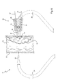
- FIG. 1 to 6 illustrated first embodiment of a reduction forceps according to the invention is designated in its entirety by the reference numeral 10.
- the reduction forceps 10 has two forceps halves 12 and 14, which are connected by a hinge 16 like a scissor about this hinge 16 pivotally connected to each other.
- Out Fig. 1 It can be seen that the forceps halves 12 and 14, viewed over a central longitudinal axis 17 of the reduction forceps 10, are formed approximately mirror-inverted.
- each pliers half 12 or 14 has an industry 20 or 22.
- teeth 43 of the locking bar 42 can be seen, which cooperate with corresponding, not shown here teeth of the locking bar 44.
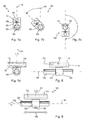
- the drilling aid 50 consists of an approximately block-shaped block 52nd
- the drilling aid 50 or the block 52 is thereby mounted laterally on the branch 22 via the bolt 54, so that the drilling aid 50 is basically rotatable through 360 ° about the axis of rotation 58.
- the pivoting range from the center position of Fig. 3A each about 20 °.
- Fig. 5 From the presentation of Fig. 5 It can also be seen that the guide channels 64 and 66 are provided with corresponding inlet slopes 69 and 71, respectively, in order to facilitate the introduction of a drilling tool, for example a spiked wire or a drill.
- a drilling tool for example a spiked wire or a drill.
- the height 68 of the block 52 is only slightly larger than the outer diameter 70 of the industry 22, that is, the block 52 builds very compact in terms of height. It will also be appreciated that the industry 22 is flattened in the portion where the block 52 is mounted. As a result, the height is kept low in this section.
- the drilling channels 82 and 84 can also be set at other locations, for example, a channel in the representation of Fig. 6 above, another below - depending on how this is best for fixing the broken bone piece 79.
- the guide channel 112 extends in the direction of the central longitudinal axis 105 of the industry 104.
- the inclined guide of the guide shaft 113 is only an illustrated embodiment; the guide channel 112 may also extend parallel to the pliers plane 109.
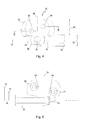
- Fig. 9 a third embodiment of a reduction forceps is shown, again here the reduction forceps is designed as such as the same in Fig. 1 illustrated reduction forceps 10.
- the sleeve 122 is designed such that it covers the outer surface 124 of the branch 126, which in turn corresponds to the branch 22 of the exemplary embodiment of FIG Fig. 1 corresponds, completely encompasses and rests against this.
- the central longitudinal axis of the branch 126 lies in the forceps plane 134 of the reduction forceps.
- a guide block 130 is rotatably mounted on the sleeve via a pivot pin, so that the guide block 130 can be rotated about a rotation axis 131 perpendicular to the pliers plane 134.
- the guide block 130 extends a continuous guide channel 132 which is not inclined, that is, whose central longitudinal axis is parallel to the pliers plane 134th
- the guide block 130 is rotatable with the guide channel 132 about a rotation axis 131 around the sleeve 122 again.
- the sleeve 122 itself and thus the complete drilling aid 120 is rotatable about the longitudinal axis of the industry 126, as previously described.
- the entire drilling aid 120 can be moved by loosening the locking device along the industry 136, as indicated by the double arrow 129.
- a plurality of bore channels can also be formed, as described in connection with FIG Fig. 1 are described.
Landscapes
- Health & Medical Sciences (AREA)
- Surgery (AREA)
- Life Sciences & Earth Sciences (AREA)
- Orthopedic Medicine & Surgery (AREA)
- Biomedical Technology (AREA)
- Nuclear Medicine, Radiotherapy & Molecular Imaging (AREA)
- Engineering & Computer Science (AREA)
- Heart & Thoracic Surgery (AREA)
- Medical Informatics (AREA)
- Molecular Biology (AREA)
- Animal Behavior & Ethology (AREA)
- General Health & Medical Sciences (AREA)
- Public Health (AREA)
- Veterinary Medicine (AREA)
- Oral & Maxillofacial Surgery (AREA)
- Dentistry (AREA)
- Surgical Instruments (AREA)
Applications Claiming Priority (1)
| Application Number | Priority Date | Filing Date | Title |
|---|---|---|---|
| DE102010051919A DE102010051919A1 (de) | 2010-11-10 | 2010-11-10 | Repositionszange mit einer Bohrhilfe |
Publications (2)
| Publication Number | Publication Date |
|---|---|
| EP2452644A2 true EP2452644A2 (fr) | 2012-05-16 |
| EP2452644A3 EP2452644A3 (fr) | 2014-07-02 |
Family
ID=45440078
Family Applications (1)
| Application Number | Title | Priority Date | Filing Date |
|---|---|---|---|
| EP11188352.6A Withdrawn EP2452644A3 (fr) | 2010-11-10 | 2011-11-09 | Pince de repositionnement dotée d'une aide au forage |
Country Status (3)
| Country | Link |
|---|---|
| US (1) | US20120123428A1 (fr) |
| EP (1) | EP2452644A3 (fr) |
| DE (1) | DE102010051919A1 (fr) |
Cited By (1)
| Publication number | Priority date | Publication date | Assignee | Title |
|---|---|---|---|---|
| CN104546064A (zh) * | 2014-12-26 | 2015-04-29 | 上海交通大学医学院附属第九人民医院 | 钳型肩锁关节复位导向系统 |
Families Citing this family (18)
| Publication number | Priority date | Publication date | Assignee | Title |
|---|---|---|---|---|
| ES2402846T3 (es) * | 2009-11-20 | 2013-05-09 | Facet-Link Inc | Instrumento de guía quirúrgica para trabajar en apófisis de articulaciones facetarias en columnas vertebrales |
| CN102772236A (zh) * | 2012-08-10 | 2012-11-14 | 贝朝涌 | 组合式持骨钳 |
| US9549771B1 (en) * | 2013-11-28 | 2017-01-24 | Xiao Wei Yu | Fingerstall-cannulated guide for fast and accurate guide wire positioning |
| DE102014102001A1 (de) | 2014-02-18 | 2015-08-20 | Karl Storz Gmbh & Co. Kg | Repositionszange mit verschwenkbaren Fixierelementen |
| CN103860242A (zh) * | 2014-03-11 | 2014-06-18 | 金彩芹 | 一种妇产科止血钳 |
| US20150313640A1 (en) * | 2014-04-30 | 2015-11-05 | Andres Eduardo O'DALY | Surgical instrument with movable guide and sleeve |
| US10179001B2 (en) * | 2014-06-30 | 2019-01-15 | DePuy Synthes Products, Inc. | Bone reduction forceps and plate holding forceps |
| US10123832B2 (en) * | 2014-08-08 | 2018-11-13 | Stryker European Holdings I, Llc | Surgical forceps system |
| CN104224294B (zh) * | 2014-10-15 | 2016-04-27 | 山东省文登整骨医院 | 本奈特骨折固定器 |
| US10543004B2 (en) * | 2015-12-23 | 2020-01-28 | Osteomed Llc | Bone centering drill guide |
| WO2017137974A1 (fr) * | 2016-02-09 | 2017-08-17 | Marc Waisman | Pinces-aiguilles à os et pointes d'aiguilles canulées destinées à être utilisées en tant qu'aiguilles de perfusion squelettique et procédés associés |
| CN106108989A (zh) * | 2016-06-13 | 2016-11-16 | 权晓慧 | 一种长度可调的磁力血管钳 |
| US20180008286A1 (en) | 2016-07-05 | 2018-01-11 | Mortise Medical, LLC | Noncircular broach and methods of use |
| CN106955150B (zh) * | 2017-03-30 | 2018-02-23 | 马良 | 一种骨外科磁力导向复位固定装置 |
| US20200138457A1 (en) * | 2017-04-26 | 2020-05-07 | Lorean Dynamic Surgical Navigation Ltd. | Surgical drill guide tools |
| CN108939275B (zh) * | 2018-06-05 | 2023-09-22 | 无锡市人民医院 | 脐部清洁装置 |
| CN109199556B (zh) * | 2018-10-13 | 2023-09-29 | 范士洁 | 一种偏心单臂骨牵引装置 |
| CN111297462A (zh) * | 2020-02-20 | 2020-06-19 | 中国人民解放军陆军军医大学第一附属医院 | 一种骨折复位钳 |
Citations (3)
| Publication number | Priority date | Publication date | Assignee | Title |
|---|---|---|---|---|
| US2181746A (en) | 1939-02-04 | 1939-11-28 | John R Siebrandt | Combination bone clamp and adjustable drill guide |
| DE3203451A1 (de) | 1981-02-27 | 1982-12-16 | Mo och Domsjö AB, 89191 Örnsköldsvik | Zangenartiges chirurgisches instrument |
| DE102007008918A1 (de) | 2007-02-23 | 2008-08-28 | Johann Heinz Waldrich | Carpus-Zielzange mit integrierter axial-zentrischer Bohrführung nach Professor Krimmer |
Family Cites Families (13)
| Publication number | Priority date | Publication date | Assignee | Title |
|---|---|---|---|---|
| DE8323877U1 (de) | 1983-08-19 | 1984-01-26 | Fa. Ad. Krauth, 2000 Hamburg | Repositionszange |
| US5375588A (en) * | 1992-08-17 | 1994-12-27 | Yoon; Inbae | Method and apparatus for use in endoscopic procedures |
| US5578032A (en) * | 1994-12-20 | 1996-11-26 | Accurate Surgical & Scientific Instruments Corporation | Bone clamp |
| US5697933A (en) * | 1995-12-18 | 1997-12-16 | Medicinelodge, Inc. | Bone-tendon-bone drill guide |
| US6042540A (en) * | 1997-08-18 | 2000-03-28 | Pacific Surgical Innovations, Inc. | Side-loading surgical retractor |
| US7887544B2 (en) * | 2003-03-10 | 2011-02-15 | Tornier Sas | Ancillary tool for positioning a glenoid implant |
| US20070093848A1 (en) * | 2005-09-29 | 2007-04-26 | Peter Harris | Cervical drill guide apparatus |
| DE202005015975U1 (de) * | 2005-10-10 | 2007-02-08 | Synthes Gmbh | Zielgerät |
| US8512385B2 (en) * | 2006-07-07 | 2013-08-20 | Swiss Pro Orthopedic Sa | Bone plate with complex, adjacent holes joined by a bend relief zone |
| US8080045B2 (en) * | 2008-04-08 | 2011-12-20 | Wotton Iii Harold M | Bone clamp |
| US8167891B2 (en) * | 2008-07-21 | 2012-05-01 | Osteomed Llc | System and method for fracture reduction |
| ES2402846T3 (es) * | 2009-11-20 | 2013-05-09 | Facet-Link Inc | Instrumento de guía quirúrgica para trabajar en apófisis de articulaciones facetarias en columnas vertebrales |
| GB201009319D0 (en) * | 2010-06-03 | 2010-07-21 | Univ Robert Gordon | Surgical guide device |
-
2010
- 2010-11-10 DE DE102010051919A patent/DE102010051919A1/de not_active Withdrawn
-
2011
- 2011-11-09 EP EP11188352.6A patent/EP2452644A3/fr not_active Withdrawn
- 2011-11-10 US US13/293,307 patent/US20120123428A1/en not_active Abandoned
Patent Citations (3)
| Publication number | Priority date | Publication date | Assignee | Title |
|---|---|---|---|---|
| US2181746A (en) | 1939-02-04 | 1939-11-28 | John R Siebrandt | Combination bone clamp and adjustable drill guide |
| DE3203451A1 (de) | 1981-02-27 | 1982-12-16 | Mo och Domsjö AB, 89191 Örnsköldsvik | Zangenartiges chirurgisches instrument |
| DE102007008918A1 (de) | 2007-02-23 | 2008-08-28 | Johann Heinz Waldrich | Carpus-Zielzange mit integrierter axial-zentrischer Bohrführung nach Professor Krimmer |
Cited By (1)
| Publication number | Priority date | Publication date | Assignee | Title |
|---|---|---|---|---|
| CN104546064A (zh) * | 2014-12-26 | 2015-04-29 | 上海交通大学医学院附属第九人民医院 | 钳型肩锁关节复位导向系统 |
Also Published As
| Publication number | Publication date |
|---|---|
| EP2452644A3 (fr) | 2014-07-02 |
| US20120123428A1 (en) | 2012-05-17 |
| DE102010051919A1 (de) | 2012-05-10 |
Similar Documents
| Publication | Publication Date | Title |
|---|---|---|
| EP2452644A2 (fr) | Pince de repositionnement dotée d'une aide au forage | |
| DE69834350T2 (de) | Rongeur | |
| EP1784137B1 (fr) | Instrument chirurgical | |
| DE102007036943B4 (de) | Fußchirurgie-Knochenplatte | |
| EP2859855B1 (fr) | Pince de repositionnement doté d'une déformation double à 90° pour la répartition sur deux plans | |
| EP2213254B1 (fr) | Instrument chirurgical | |
| DE202005021068U1 (de) | Chirurgisches Maulinstrument | |
| EP2221006A1 (fr) | Instrument médical destiné à la préhension de matériau de suture chirurgical | |
| WO2017133967A1 (fr) | Instrument d'incision mini-invasif à partie guidée réutilisable | |
| WO2008068564A2 (fr) | Instrument chirurgical pour implanter un fil métallique, de préférence dans un os | |
| EP2853212B1 (fr) | Instrument chirurgical | |
| EP2497433B1 (fr) | Système de trocart multiple | |
| EP1354562B1 (fr) | Système d' ostéosynthèse | |
| EP1319372B1 (fr) | Dispositif pour tenir un manchon de trocart | |
| EP1455662B1 (fr) | Dispositif de visee destine a une broche a fracture | |
| EP2814406B1 (fr) | Dispositif permettant l'application d'une pince chirurgicale | |
| EP2725988B1 (fr) | Système de trocart | |
| EP0797407A2 (fr) | Instrument chirurgical | |
| EP1587434A1 (fr) | Instrument medical pour la dissection de tissus | |
| AT516604B1 (de) | Instrument zum Entfernen von Körpergewebe aus einem Fistelgang | |
| DE102014119011A1 (de) | Positionierungsvorrichtung für die Anbringung von Befestigungselementen in Knochen | |
| EP3773264B1 (fr) | Instrument d'application d'électrodes | |
| DE102006036117B4 (de) | Chirurgisches Instrument zum Spreizen von zwei zueinander benachbarten Operationsöffnungen | |
| DE102014102001A1 (de) | Repositionszange mit verschwenkbaren Fixierelementen | |
| CH721505A1 (de) | Vorrichtung zur osteosynthetischen Versorgung von Knochenfrakturen, insbesondere Patellafrakturen |
Legal Events
| Date | Code | Title | Description |
|---|---|---|---|
| PUAI | Public reference made under article 153(3) epc to a published international application that has entered the european phase |
Free format text: ORIGINAL CODE: 0009012 |
|
| AK | Designated contracting states |
Kind code of ref document: A2 Designated state(s): AL AT BE BG CH CY CZ DE DK EE ES FI FR GB GR HR HU IE IS IT LI LT LU LV MC MK MT NL NO PL PT RO RS SE SI SK SM TR |
|
| AX | Request for extension of the european patent |
Extension state: BA ME |
|
| PUAL | Search report despatched |
Free format text: ORIGINAL CODE: 0009013 |
|
| AK | Designated contracting states |
Kind code of ref document: A3 Designated state(s): AL AT BE BG CH CY CZ DE DK EE ES FI FR GB GR HR HU IE IS IT LI LT LU LV MC MK MT NL NO PL PT RO RS SE SI SK SM TR |
|
| AX | Request for extension of the european patent |
Extension state: BA ME |
|
| RIC1 | Information provided on ipc code assigned before grant |
Ipc: A61B 17/88 20060101AFI20140526BHEP Ipc: A61B 17/17 20060101ALI20140526BHEP |
|
| STAA | Information on the status of an ep patent application or granted ep patent |
Free format text: STATUS: THE APPLICATION IS DEEMED TO BE WITHDRAWN |
|
| 18D | Application deemed to be withdrawn |
Effective date: 20150106 |