EP2452780A2 - Système pour nettoyer les dents - Google Patents
Système pour nettoyer les dents Download PDFInfo
- Publication number
- EP2452780A2 EP2452780A2 EP11009002A EP11009002A EP2452780A2 EP 2452780 A2 EP2452780 A2 EP 2452780A2 EP 11009002 A EP11009002 A EP 11009002A EP 11009002 A EP11009002 A EP 11009002A EP 2452780 A2 EP2452780 A2 EP 2452780A2
- Authority
- EP
- European Patent Office
- Prior art keywords
- liquid
- nozzle
- composition
- tooth cleaning
- cleaning mixture
- Prior art date
- Legal status (The legal status is an assumption and is not a legal conclusion. Google has not performed a legal analysis and makes no representation as to the accuracy of the status listed.)
- Granted
Links
Images


Classifications
-
- A—HUMAN NECESSITIES
- A61—MEDICAL OR VETERINARY SCIENCE; HYGIENE
- A61C—DENTISTRY; APPARATUS OR METHODS FOR ORAL OR DENTAL HYGIENE
- A61C3/00—Dental tools or instruments
- A61C3/02—Tooth drilling or cutting instruments; Instruments acting like a sandblast machine
- A61C3/025—Instruments acting like a sandblast machine, e.g. for cleaning, polishing or cutting teeth
-
- B—PERFORMING OPERATIONS; TRANSPORTING
- B05—SPRAYING OR ATOMISING IN GENERAL; APPLYING FLUENT MATERIALS TO SURFACES, IN GENERAL
- B05B—SPRAYING APPARATUS; ATOMISING APPARATUS; NOZZLES
- B05B1/00—Nozzles, spray heads or other outlets, with or without auxiliary devices such as valves, heating means
- B05B1/34—Nozzles, spray heads or other outlets, with or without auxiliary devices such as valves, heating means designed to influence the nature of flow of the liquid or other fluent material, e.g. to produce swirl
- B05B1/3405—Nozzles, spray heads or other outlets, with or without auxiliary devices such as valves, heating means designed to influence the nature of flow of the liquid or other fluent material, e.g. to produce swirl to produce swirl
- B05B1/341—Nozzles, spray heads or other outlets, with or without auxiliary devices such as valves, heating means designed to influence the nature of flow of the liquid or other fluent material, e.g. to produce swirl to produce swirl before discharging the liquid or other fluent material, e.g. in a swirl chamber upstream the spray outlet
- B05B1/3421—Nozzles, spray heads or other outlets, with or without auxiliary devices such as valves, heating means designed to influence the nature of flow of the liquid or other fluent material, e.g. to produce swirl to produce swirl before discharging the liquid or other fluent material, e.g. in a swirl chamber upstream the spray outlet with channels emerging substantially tangentially in the swirl chamber
- B05B1/3426—Nozzles, spray heads or other outlets, with or without auxiliary devices such as valves, heating means designed to influence the nature of flow of the liquid or other fluent material, e.g. to produce swirl to produce swirl before discharging the liquid or other fluent material, e.g. in a swirl chamber upstream the spray outlet with channels emerging substantially tangentially in the swirl chamber the channels emerging in the swirl chamber perpendicularly to the outlet axis
-
- B—PERFORMING OPERATIONS; TRANSPORTING
- B05—SPRAYING OR ATOMISING IN GENERAL; APPLYING FLUENT MATERIALS TO SURFACES, IN GENERAL
- B05B—SPRAYING APPARATUS; ATOMISING APPARATUS; NOZZLES
- B05B1/00—Nozzles, spray heads or other outlets, with or without auxiliary devices such as valves, heating means
- B05B1/34—Nozzles, spray heads or other outlets, with or without auxiliary devices such as valves, heating means designed to influence the nature of flow of the liquid or other fluent material, e.g. to produce swirl
- B05B1/3405—Nozzles, spray heads or other outlets, with or without auxiliary devices such as valves, heating means designed to influence the nature of flow of the liquid or other fluent material, e.g. to produce swirl to produce swirl
- B05B1/341—Nozzles, spray heads or other outlets, with or without auxiliary devices such as valves, heating means designed to influence the nature of flow of the liquid or other fluent material, e.g. to produce swirl to produce swirl before discharging the liquid or other fluent material, e.g. in a swirl chamber upstream the spray outlet
- B05B1/3421—Nozzles, spray heads or other outlets, with or without auxiliary devices such as valves, heating means designed to influence the nature of flow of the liquid or other fluent material, e.g. to produce swirl to produce swirl before discharging the liquid or other fluent material, e.g. in a swirl chamber upstream the spray outlet with channels emerging substantially tangentially in the swirl chamber
- B05B1/3431—Nozzles, spray heads or other outlets, with or without auxiliary devices such as valves, heating means designed to influence the nature of flow of the liquid or other fluent material, e.g. to produce swirl to produce swirl before discharging the liquid or other fluent material, e.g. in a swirl chamber upstream the spray outlet with channels emerging substantially tangentially in the swirl chamber the channels being formed at the interface of cooperating elements, e.g. by means of grooves
- B05B1/3442—Nozzles, spray heads or other outlets, with or without auxiliary devices such as valves, heating means designed to influence the nature of flow of the liquid or other fluent material, e.g. to produce swirl to produce swirl before discharging the liquid or other fluent material, e.g. in a swirl chamber upstream the spray outlet with channels emerging substantially tangentially in the swirl chamber the channels being formed at the interface of cooperating elements, e.g. by means of grooves the interface being a cone having the same axis as the outlet
-
- B—PERFORMING OPERATIONS; TRANSPORTING
- B05—SPRAYING OR ATOMISING IN GENERAL; APPLYING FLUENT MATERIALS TO SURFACES, IN GENERAL
- B05B—SPRAYING APPARATUS; ATOMISING APPARATUS; NOZZLES
- B05B1/00—Nozzles, spray heads or other outlets, with or without auxiliary devices such as valves, heating means
- B05B1/34—Nozzles, spray heads or other outlets, with or without auxiliary devices such as valves, heating means designed to influence the nature of flow of the liquid or other fluent material, e.g. to produce swirl
- B05B1/3405—Nozzles, spray heads or other outlets, with or without auxiliary devices such as valves, heating means designed to influence the nature of flow of the liquid or other fluent material, e.g. to produce swirl to produce swirl
- B05B1/341—Nozzles, spray heads or other outlets, with or without auxiliary devices such as valves, heating means designed to influence the nature of flow of the liquid or other fluent material, e.g. to produce swirl to produce swirl before discharging the liquid or other fluent material, e.g. in a swirl chamber upstream the spray outlet
- B05B1/3421—Nozzles, spray heads or other outlets, with or without auxiliary devices such as valves, heating means designed to influence the nature of flow of the liquid or other fluent material, e.g. to produce swirl to produce swirl before discharging the liquid or other fluent material, e.g. in a swirl chamber upstream the spray outlet with channels emerging substantially tangentially in the swirl chamber
- B05B1/3431—Nozzles, spray heads or other outlets, with or without auxiliary devices such as valves, heating means designed to influence the nature of flow of the liquid or other fluent material, e.g. to produce swirl to produce swirl before discharging the liquid or other fluent material, e.g. in a swirl chamber upstream the spray outlet with channels emerging substantially tangentially in the swirl chamber the channels being formed at the interface of cooperating elements, e.g. by means of grooves
- B05B1/3447—Nozzles, spray heads or other outlets, with or without auxiliary devices such as valves, heating means designed to influence the nature of flow of the liquid or other fluent material, e.g. to produce swirl to produce swirl before discharging the liquid or other fluent material, e.g. in a swirl chamber upstream the spray outlet with channels emerging substantially tangentially in the swirl chamber the channels being formed at the interface of cooperating elements, e.g. by means of grooves the interface being a cylinder having the same axis as the outlet
-
- B—PERFORMING OPERATIONS; TRANSPORTING
- B05—SPRAYING OR ATOMISING IN GENERAL; APPLYING FLUENT MATERIALS TO SURFACES, IN GENERAL
- B05B—SPRAYING APPARATUS; ATOMISING APPARATUS; NOZZLES
- B05B7/00—Spraying apparatus for discharge of liquids or other fluent materials from two or more sources, e.g. of liquid and air, of powder and gas
- B05B7/24—Spraying apparatus for discharge of liquids or other fluent materials from two or more sources, e.g. of liquid and air, of powder and gas with means, e.g. a container, for supplying liquid or other fluent material to a discharge device
- B05B7/2402—Apparatus to be carried on or by a person, e.g. by hand; Apparatus comprising containers fixed to the discharge device
- B05B7/2462—Apparatus to be carried on or by a person, e.g. by hand; Apparatus comprising containers fixed to the discharge device using a carrying liquid flowing through the container for dissolving a block of solid material
-
- B—PERFORMING OPERATIONS; TRANSPORTING
- B24—GRINDING; POLISHING
- B24C—ABRASIVE OR RELATED BLASTING WITH PARTICULATE MATERIAL
- B24C5/00—Devices or accessories for generating abrasive blasts
- B24C5/02—Blast guns, e.g. for generating high velocity abrasive fluid jets for cutting materials
- B24C5/04—Nozzles therefor
-
- B—PERFORMING OPERATIONS; TRANSPORTING
- B24—GRINDING; POLISHING
- B24C—ABRASIVE OR RELATED BLASTING WITH PARTICULATE MATERIAL
- B24C7/00—Equipment for feeding abrasive material; Controlling the flowability, constitution, or other physical characteristics of abrasive blasts
- B24C7/0007—Equipment for feeding abrasive material; Controlling the flowability, constitution, or other physical characteristics of abrasive blasts the abrasive material being fed in a liquid carrier
-
- A—HUMAN NECESSITIES
- A61—MEDICAL OR VETERINARY SCIENCE; HYGIENE
- A61C—DENTISTRY; APPARATUS OR METHODS FOR ORAL OR DENTAL HYGIENE
- A61C17/00—Devices for cleaning, polishing, rinsing or drying teeth, teeth cavities or prostheses; Saliva removers; Dental appliances for receiving spittle
- A61C17/02—Rinsing or air-blowing devices, e.g. using fluid jets or comprising liquid medication
Definitions
- the present invention generally relates to the field of tooth cleaning.
- Mouth showers are known as a means for cleaning teeth and are used to clean teeth, interdental spaces and gums with a jet of liquid. It is generally used under pressure from a nozzle water, mouthwash, etc. used.
- the object of the present invention is to provide solutions that at least reduce the disadvantages of known oral showers.
- the invention provides a tooth cleaning system, a tooth cleaning mixture, a receiving structure for the tooth cleaning mixture, a rinsing device for rinsing the tooth cleaning mixture and mixing of liquid with the rinsed tooth cleaning mixture to a tooth cleaning suspension and a nozzle for dispensing the tooth cleaning suspension according to the independent claims ready.
- the tooth cleaning system comprises a fluid supply line via which fluid can be conducted to the operating element; a flushing device connectable to a fluid source for receiving a tooth cleaning mixture and for flushing out constituents of the tooth cleaning mixture by means of liquid supplied from the liquid source and mixing flushed constituents and liquid; and a nozzle in fluid communication with the purging device for delivering the mixture of purged ingredients of the tooth cleaning mixture and liquid for cleaning teeth.
- the dentifrice composition is provided as a multi-layered tablet, wherein a composition of each layer comprises abrasive constituents of magnesium oxide (MgO) and crosslinked polyvinylpyrrolidone (PVP) and further binder.
- MgO magnesium oxide
- PVP polyvinylpyrrolidone
- the ratio of the abrasive constituents in the tablet layers is different, in particular such that the magnesium oxide content decreases gradually from the outside in and the PVP content gradually decreases from the inside to the outside, preferably to the same extent.
- the receiving structure for a tooth cleaning mixture has a receiving space for receiving a tooth cleaning mixture and at least one inlet opening for supplying liquids into the receiving space and at least one outlet opening for exporting liquid and components flushed out of the tooth cleaning mixture by means of liquid.
- the flushing device comprises a housing, a flushing chamber in the housing, a liquid inlet into the flushing chamber, a liquid outlet from the flushing chamber, and a dentifrice mixing fixture disposed in the flushing chamber, the fixture being at least partially resilient to exert a biasing force on the dentifrice mixing mixture.
- the tooth-cleaning nozzle which is made, for example, of an at least partially flexible material, in particular of a semi-rigid plastic, has a pressure chamber which can be supplied with liquid via a fluid supply line, a pressure chamber arranged in the pressure chamber
- Swirling agent which is formed on the inside of the pressure chamber, a nozzle outlet opening, and arranged between the pressure chamber and the nozzle outlet opening and tapering in the direction of the nozzle outlet opening towards the compression region.
- Tableted dentifrice blends are easy to dose and hand compared to powdered ones. Due to their compact structure, they are easy to store and transport. For tablet production, powdery ingredients are mixed and pressed.
- Part of the invention is the use of magnesium oxide (MgO) and cross-linked polyvinylpyrrolidone (PVP) as abrasive ingredients in the dentifrice mixture.
- MgO magnesium oxide
- PVP polyvinylpyrrolidone
- These abrasive ingredients have properties similar to those of enamel, which can reduce the risk of tooth damage. Biofilms and deposits on teeth can thus be removed largely and gently on a daily basis. Further, these abrasive ingredients aid in uniform rinsing of the tooth cleaning mixture in a fluid stream. Used in known tooth cleaning mixtures, not used for cleaning teeth ingredients that promote a rinse the dentifrice mixture, can be at least reduced. Under rinsing is here and below understood in particular a detachment of the abrasive components from the tooth cleaning mixture by means of liquid.
- Magnesium oxide is z. B. approved as a food additive in the European Community and is suitable for dental care.
- Crosslinked PVP polyvinylpyrrolidone
- a tablet according to the invention Due to the composition, a tablet according to the invention hardly dissolves in water. To rinse the components, a liquid flow is required. Therefore, a tablet can be used after breaks and remain when not in use in a tooth cleaning system.
- a higher proportion of MgO can be used on the outer layer than in the core layer.
- the MgO may come into contact with a liquid stream intended for rinsing, which means that upon contact with water, the substances breaking up the tablet structure can at least be reduced.
- the composition of the core layer may include 40% MgO and 50% PVP.
- the composition of the core layer may include 40% ⁇ 1 MgO and 50% ⁇ 1 PVP.
- the composition of the core layer may include 40% ⁇ 2 MgO and 50% ⁇ 2 PVP.
- the composition of the core layer may include 40% ⁇ 3 MgO and 50% ⁇ 3 PVP.
- the composition of the core layer may include 40% ⁇ 4 MgO and 50% ⁇ 4 PVP.
- the composition of the core layer may include 40% ⁇ 5 MgO and 50% ⁇ 5 PVP.
- the composition of the core layer may include 40% ⁇ 6 MgO and 50% ⁇ 6 PVP.
- the composition of the core layer may include 40% ⁇ 7 MgO and 50% ⁇ 7 PVP.
- the composition of the core layer may include 40% ⁇ 8 MgO and 50% ⁇ 8 PVP.
- the composition of the core layer may include 40% ⁇ 9 MgO and 50% ⁇ 9 PVP.
- the composition of the core layer may include 40% ⁇ 10MgO and 50% ⁇ 10 PVP.
- the composition of the outer layer may include 60% MgO and 30% PVP.
- the composition of the outer layer may include 60% ⁇ 1 MgO and 30% ⁇ 1 PVP.
- the composition of the outer layer may include 60% ⁇ 2 MgO and 30% ⁇ 2 PVP.
- the composition of the outer layer may include 60% ⁇ 3 MgO and 30% ⁇ 3 PVP.
- the composition of the outer layer may include 60% ⁇ 4 MgO and 30% ⁇ 4 PVP.
- the composition of the outer layer may include 60% ⁇ 5 MgO and 30% ⁇ 5 PVP.
- the composition of the outer layer may include 60% ⁇ 6MgO and 30% ⁇ 6 PVP.
- the composition of the outer layer may include 60% ⁇ 7 MgO and 30% ⁇ 7 PVP.
- the composition of the outer layer may include 60% ⁇ 8MgO and 30% ⁇ 8 PVP.
- the composition of the outer layer may include 60% ⁇ 9 MgO and 30% ⁇ 9 PVP.
- the composition of the outer layer may include 60% ⁇ 10MgO and 30% ⁇ 10 PVP.
- At least one intermediate layer may be formed between the core layer and the outer layer.
- the composition of the intermediate layer may include 50% MgO and 40% PVP.
- the composition of the intermediate layer may comprise 50% ⁇ 1 MgO and 40% ⁇ 1 PVP.
- the composition of the intermediate layer may include 50% ⁇ 2 MgO and 40% ⁇ 2 PVP.
- the composition of the intermediate layer may include 50% ⁇ 3 MgO and 40% ⁇ 3 PVP.
- the composition of the intermediate layer may include 50% ⁇ 4 MgO and 40% ⁇ 4 PVP.
- the composition of the intermediate layer may include 50% ⁇ 5 MgO and 40% ⁇ 5 PVP.
- the composition of the intermediate layer may include 50% ⁇ 6 MgO and 40% ⁇ 6 PVP.
- the composition of the intermediate layer may include 50% ⁇ 7 MgO and 40% ⁇ 7 PVP.
- the composition of the intermediate layer may include 50% ⁇ 8MgO and 40% ⁇ 8 PVP.
- the composition of the intermediate layer may include 50% ⁇ 9 MgO and 40% ⁇ 9 PVP.
- the composition of the intermediate layer may comprise 50% ⁇ 10% MgO and 40% ⁇ 10% PVP.
- the distribution of constituents may change discretely from the outer layer 60% MgO to the core layer with 30% PVP.
- the remaining constituents in the layers may comprise binding and / or shaping agents, e.g. Magnesium stearate and / or additives (for example fragrances and / or flavoring substances, dental active substance).
- binding and / or shaping agents e.g. Magnesium stearate and / or additives (for example fragrances and / or flavoring substances, dental active substance).
- the core layer can contain about 40% MgO and about 50% PVP, which leads there to a more rapid rinsing of a substantially reducing to the core layer tablet with a - based on the eroding liquid amount - a uniform proportion of abrasive constituents.
- the composition of the respective layer for improving slip properties may comprise hydrophobic portions, in particular 1% of finely divided silica.
- the dentifrice mixture may also contain other medicinal, cosmetic or olfactory ingredients.
- the receiving structure may be made of a woven fabric or a mesh, mesh or grid structure.
- Contemplated materials therefor include, for example, metal (eg, wire), plastic (eg, in filament or fiber form, eg, nylon, thermoplastic, bio-plastic) and blends thereof.
- a liquid stream flowing around the receiving structure, such as water, allows rinsing of the abrasive components of a held by the receiving structure tooth cleaning mixture.
- the inlet and outlet openings may be arranged and / or formed such that a liquid flow flowing through the inlet opening (s) substantially completely flows around the tooth-cleaning mixture. Further, they may be arranged and / or configured such that a fluid stream first contacts predetermined areas of a tooth cleaning mixture (eg, edge (s), edges, side surface (s)).
- the outlet opening (s) may allow liquid to pass through with triggered abrasive components. Furthermore, they can enable a homogeneous liquid flow with purged components.
- the outlet port (s) may be sized to retain particulates or particles of predetermined size and above in the containment structure. Clogging of downstream lines, nozzles, etc. can be avoided.
- Residues can be comminuted and rinsed out again in the liquid stream or disposed of with the receiving structure.
- the receiving structure can be composed of two sub-elements.
- the receiving structure may be formed like a disk, z. B. so that a tooth cleaning mixture can be aligned substantially at a right angle to a liquid flow without turning.
- the sub-elements can be connectable to each other via connecting regions to a connecting portion.
- suitable measures such as welding, fusing, etc. are possible.
- the connecting portion may be for holding the receiving structure z. B. be designed in a Aus Seriesvorraum.
- the tooth cleaning mixture may be at least partially spaced from the inner surface of the receiving structure.
- a space or distance between the tooth cleaning mixture and the receiving structure may aid in flushing out the tablet ingredients, e.g. B. when movement of the tooth cleaning mixture causes mechanical abrasion.
- a substantially all-round flushing can thus be ensured.
- the distance may be approximately 1/10 to 1/20 of the diameter of the tooth cleaning mixture.
- the inlet and outlet ports may be designed to permit a homogeneous fluid flow with components flushed out of the tooth cleaning mixture.
- the receiving structure may be formed like a disk. So z. B. a flat tablet form be exposed to a liquid flow without turning.
- the receiving structure may also have other geometries, e.g. adapted to a tablet form or another embodiment of the tooth cleaning mixture.
- the receiving structure may be pyramid-shaped, cuboid or polyhedron-shaped.
- the liquid stream can wash and apply the tooth cleaning mixture from all sides.
- the liquid flow can cause the tooth cleaning mixture to vibrate and move.
- the tooth cleaning mixture is flushed out through interaction with the liquid flow itself.
- additional abrasive components can be dissolved out.
- a structural component can z. B. serve a receiving structure or the Aus Seriesvorraum itself.
- the at least partially elastic configuration of the rinsing-out device ensures that the tooth-cleaning mixture is kept in an ideal rinsing position ("sweet spot") even with decreasing volumes.
- the center of gravity of the tooth cleaning mixture can be aligned relative to the liquid flow and z. B. be kept centered in the liquid stream.
- the holding device may comprise at least two elastic fingers, which are able to hold the tooth cleaning mixture elastically biased.
- the fingers may be formed as at least two elastic plastic holder, on which rests a tooth cleaning mixture.
- the tooth cleaning mixture can be arranged in a receiving structure above.
- the flushing device may have a screen structure.
- the biasing force (generated, for example, by the finger and / or receiving structure) may force the dentifrice mixture against the screen structure.
- the screen structure may be disposed at an outlet of the Aus Naturallyracsch.
- the resilient biasing force keeps the tooth cleaning mixture positioned even with decreasing volume (eg, by pressure in the direction of the screen structure).
- the resilient biasing force also allows the tooth cleaning mixture to move in the fluid stream.
- the tooth cleaning mixture In the case of fingers z. B. on a liquid flow and possibly in addition to the outgassing / swelling of the explosive PVP the tooth cleaning mixture to move on the fingers and with these.
- the tooth cleaning mixture can be accommodated in a receiving structure according to the invention which elastically holds the holding device in the flushing chamber.
- the pressure of inflowing liquid can be between 4 bar and 10 bar.
- the purging device may comprise a swirl element for swirling liquid introduced into the purging device.
- the swirling element causes a tapered liquid flow in the scavenging chamber to turbulence or a swirling rotating movement.
- the arrangement of the liquid inlet and / or the liquid outlet may assist the effect of the swirling element.
- the swirling element can be designed cylindrical and introduce liquid, for example via oblique holes in a vortex chamber.
- the swirling element can be integrated in the same structure as the holding device. For this purpose is z. B. possible to form one or more passages or channels in the holding device, which provide (possibly by appropriate flow) for a turbulence.
- the geometry of the flushing out device in particular the flushing out chamber, can be designed so that the tablet is always flushed around on all sides and substrate is continuously flushed out, even if the size of the tablet is reduced by the removal of the outer layers.
- the diameter of the Aus Schwarzsch can be slightly larger than the tablet, so that it can be easily inserted and guided on the inner wall.
- the length of the vortex chamber can be adjusted so that the volume remains as small as possible in order to keep the pressure conditions throughout the system as equal as possible.
- a use of a Aus Whyvorraum invention is provided for rinsing a tooth cleaning mixture in a dental cleaning system.
- the Austicianvortechnische may include a top and a bottom, which are coupled together.
- a snap or snap fastener or screw cap or other suitable mechanism can be used.
- semi-rigid plastics such as polymethyl methacrylate (PMMA) or hard polyvinyl chloride (PVC) can be used as a partially flexible material.
- PMMA polymethyl methacrylate
- PVC hard polyvinyl chloride
- the partially flexible material prevents blockages by abrasive particles, in that it is deformable, in particular on a microscopic scale, in such a way that a self-vibration of the nozzle is possible upon passage of the liquid suspension.
- deposits of suspension components can be reduced and short-term deposits are replaced again.
- the wear of the nozzle can be reduced and a sufficient strength for inlet pressures of 4 bar - 10 bar can be ensured.
- the swirling means may conically narrow and / or be configured spirally or cylindrically.
- the swirling agent swirls fluid flowing through the nozzle and can force it into the compression area.
- the swirling means can cause a twisting, which starts (immediately) before the compression zone and then allows a smooth current flow.
- the inner walls of the compression region can be smooth, for example coated, formed.
- a circular widening of the nozzle opening or the nozzle mouth can be between 30 ° and 60 °, in particular 45 ° to the nozzle longitudinal axis at the outlet opening.
- the nozzle can be designed as a hollow cone nozzle.
- the tooth cleaning mixture may be arranged in a above receiving structure.
- the tooth cleaning system can have an operating element in or on which the flushing device can be arranged.
- the tooth cleaning system may comprise the fluid source, or be connected to a separate fluid source.
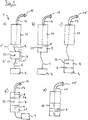
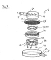
- Fig. 1a to d show various embodiments of a tooth cleaning system 1.
- the tooth cleaning systems 1 each comprise a liquid source 3, a liquid supply line 5, a flushing device 7, a liquid discharge 9, an operating element 11 and a nozzle attachment 13 with a nozzle 15.
- the liquid source 3 may be formed as a water tank with a pump device integrated therein or connected thereto; or for example by connection to a domestic water pipe ("faucet"), with a z. B. arranged in front of the Aus Seriesvortechnisch 7 pumping device also here z. B. can generate pulsating liquid flow.
- the pumping device can also be arranged upstream of the flushing device 7. Liquid passes from the liquid source 3 via the liquid feed line 5 to the flushing device 7.
- the flushing device 7 is arranged between operating element 11 and liquid source 3 and the lines 5 and 9 extending between them.
- This can be z. B. allow to integrate the invention in a conventional dental cleaning system (oral irrigator) by the Aus Hughesvorraum 3 is inserted between the liquid source 3 and the control element 11.
- the flushing device 7 is coupled to the operating element 11.
- the flushing device 7 can be connected to one end of the control element (for example adhesively bonded, welded, screwed, etc.) or formed integrally therewith.
- This variant is z. B. for dental cleaning systems used in which the liquid source 3 (possibly with one of these associated pumping device) is designed as a separate tank to allow a small, the operating means 11 comprehensive handle.
- the Aus Hughesvortechnisch 7 is disposed within the control element 11.
- This variant can z. B. are used when in the illustrative lower end of the operating element 11, a pumping device and / or a power supply is arranged.
- the flushing device 7 is coupled to the liquid source 3.
- the Aus Hughesvortechnisch 7 connected to the liquid source 3 (glued, welded, bolted, etc.) or be formed integrally therewith.
- an adapter attachment for connection with a corresponding counterpart of the Austicianvortechnik 7 can be used. This variant is also suitable for retrofitting.
- FIG. 1e shown embodiment shows a component integrating all components above structurally.
- Fig. 1a to 1e can the hydration, as in Fig. 1a shown, via one or more supplementary or optional liquid line 5 'and / or 5 ".These, as shown by the side introduction can cause additional turbulence of the introduced liquid flow.
- Aus confusevorettivocardi 7 is when using a tooth cleaning mixture z. B. in the form of a tablet 21 or arranged as granules.
- the introduced liquid stream flows around the tooth cleaning mixture and in particular triggers off its abrasive components.
- the liquid mixes with these ingredients to a tooth cleaning suspension.
- Fig. 1a to 1e can the derivation of the tooth cleaning suspension from the Aus Hughesvortechnisch 7, as in Fig. 1a shown to take place via at least one additional or alternative liquid discharge.
- the tooth cleaning suspension is supplied from the Aus Hughesvorraum 7 through the control element 11 and the nozzle attachment 13 of the nozzle 15.
- the nozzle attachment 13 is integrally formed with the operating element or exchangeably connected thereto.
- the tooth cleaning suspension exits and is supplied to the teeth cleaning a mouth.
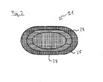
- Fig. 2 shows a tooth cleaning mixture in the form of a tablet 21.
- the tablet 21 comprises abrasive constituents which are present in a plurality of layers 23 and 25 and a core layer 27 are.
- the tablet layers 23, 25 and 27 each include magnesia and crosslinked polyvinylpyrrolidone (PVP) as abrasive ingredients.
- PVP polyvinylpyrrolidone
- PVP also counteracts the agglomeration or accumulation of magnesia constituents. PVP assists in breaking up or disrupting the structure of the tablet 21 with hydration. PVP serves as a source of "disintegrants” for "controlled” disruption of the tablet structure as it swells under hydration.
- the layers 23 and 25 and the core 27 enveloped by them differ in their composition from magnesium oxide and PVP and, if appropriate, binding and shaping agents.
- a binding and shaping agent additives such as magnesium stearate, can be used.
- the binder content can be about 5 to 15%.
- hydrophobic ingredients, such as disperse silica, can be injected to improve fluidity.
- the ratio of magnesium oxide and PVP varies from the outer layer 23 via the middle layer 25 to the core 27.
- the core 27 of the tablet 21, however, may e.g. 40% magnesium oxide and 50% PVP.
- a ratio of e.g. 50% magnesium oxide to 40% PVP is used in the middle layer 25. This allows a rapid and uniform rinsing of the tablet core 27 and thus ensure a uniform concentration of abrasive components in the tooth cleaning suspension.
- Fig. 3 shows a receiving structure 31 for receiving a tooth cleaning mixture, such as a tablet 21 or granules.
- the receiving structure 31 comprises an upper part 33a and a lower part 33b, which are each formed like a shell or discus.
- the upper part 33a and the lower part 33b are connected to each other at their edges 35a and 35b.
- To connect the edges 35a and 35b for example, welded, pressed, glued and / or coupled to each other by means of latching and / or snap connections.
- the receiving structure 31 can be made, for example, of plastic, metal, fiber fabric, glass fiber, fleece, fabric and etc. as well as mixtures of different materials. In particular, the material or materials is chosen such that the receiving structure 31 is elastically deformable.
- the receiving structure 31 is designed for use in a tooth cleaning system 1, in particular in a flushing device 7.
- the receiving structure 31 has openings 37 through which liquid can enter and escape through the tooth cleaning suspension (see above) with abrasive constituents contained therein.
- the openings 37 may, as exemplified in Fig. 3 illustrates being substantially the same size. In other embodiments, the openings 37 through which liquid is to enter may be smaller than the opening 37 through which the tooth cleaning suspension is to exit.
- the openings 37 are provided in the lattice-shaped, mesh-like, honeycomb-shaped or fabric-like upper and lower parts 33a and 33b. In further variants, the openings 37 may be provided as apertures, bores and the like.
- the openings 37 may be dimensioned such that in the suspension only abrasive components of a certain size and smaller can escape. In this way it can be avoided that e.g. Clogs or accumulations of dentifrice material may escape and / or clog elements positioned too far downstream of the pond.
- a tablet 21 is disposed within the receiving structure 31 in an exception space.
- the tablet 21 is completely received by the receiving structure 31, wherein in the present drawing, only a part is shown cut out for illustration.
- the tablet 21 and / or the receiving structure 31 are dimensioned such that the tablet 21 is movable in the receiving structure 31, whereby an operative connection with the insides of the receiving structure 31 can occur, which can lead to mechanical abrasion of the tablet 21 , Furthermore, mobility of the tablet 21 in the receiving structure 31 allows a substantially all-round flushing.
- the receiving structure 31 makes it possible to keep the tablet 21 positioned with respect to the liquid flow, so that, for example, a transverse flow-oriented tablet is not aligned or rotated in the direction of flow. Furthermore, the receiving structure causes 31 an (additional) turbulence provided for flushing the tablet 21 liquid flow. This helps flush the tablet 21.
- the receiving structure 31 can be removed and disposed of. With the receiving structure 31 also contained therein residues are removed.
- Fig. 4 shows an embodiment of a flushing device 7 z. B. for an above-mentioned tooth cleaning system. 1
- the flushing device 7 comprises a flushing chamber 42, which in the variant shown has an exemplary cylindrical shape, and is provided for receiving a tooth cleaning mixture.
- Fig. 4 shows an example of a tooth cleaning mixture in the form of a tablet 21.
- the dimensioning of Aus Hughes redesign 42 is here so that the tooth cleaning mixture can be washed around and rinsed on all sides.
- the flushing device 7 comprises an upper part 41 and a lower part 43 with a bottom element 45.
- a holding device is arranged, the podium-like holding receptacles or pads 49 has.
- the pads 49 may be at least partially elastic (eg, in their upper regions as shown).
- the pads 49 are spaced apart by intermediate spaces 51 and a central space 53.
- the pads 49 are higher on the outside as shown on their upper sides as shown. This forms a cone-shaped support for the tooth cleaning mixture.
- the support pads 49 are adapted to receive or store a tooth cleaning compound (eg, in the form of a tablet 21 or in a containment structure 31).
- a tooth cleaning compound eg, in the form of a tablet 21 or in a containment structure 31.
- the possibly existing elasticity of the holding device or its supports 49 and / or the elasticity of a receiving structure (if used) provides for a resilient biasing force acting on the tooth cleaning mixture between the holding device and an abutment formed in the upper part 41.
- a fluid supply line eg the supply line 5 of Fig. 1 Liquid is the Aus Hughes- or mixing chamber 42 fed.
- the supply of liquid can according to the Represented from below to produce a liquid flow in the vertical direction through the spaces 51 and 53.
- liquid also may be supplied (eg, laterally) to yield a liquid stream having at least in part radial and / or horizontal components, resulting in a swirling, rotating motion through the circular cross-section of the mixing chamber , This movement is maintained, so that the tablet remains flowing continuously and evenly.
- a fastening element 59 is arranged on the upper part 41, which is provided for connection to an operating element 11 of a tooth cleaning system.
- the operating element 11 may, for example, have a structure receiving the fastening element 59 and being connected to the fastening element 59, for example screwed, welded or adhesively bonded.
- a passage 61 is provided on the upper part, can be removed by the liquid suspension from the Ausêtsch 42.
- liquid is introduced into the Ausumble hamper 42, where it can be swirled, rotated.
- the liquid flow in the flushing chamber interacts with the dentifrice mixture, flushing it out and creating a dentifrice mixing suspension. This is removed through the outlet 61 and used for cleaning teeth.
- Fig. 5 shows a perspective view of another embodiment of a Aus Hughesvortechnisch 7 with a Flushing chamber or mixing chamber 42.
- the mixing chamber 42 comprises an upper part 41 and a lower part 43 with a bottom element 45. These can be connected to each other via connecting elements, such as a thread, a detent or snap mechanism. Via a liquid feed line 5, liquid is introduced through the upper part 41 into an inflow region in the lower part 43, which is located downstream as shown.
- a tooth cleaning mixture in the form of a tablet 21 is arranged in a receiving structure 31.
- the receiving structure 31 is held in the Aus choir screening 42 by a holding device.
- the receiving structure 31 rests with its edge 35 on a projection formed on the inner wall of the rinsing chamber 42.
- the receiving structure 31 lies with its underside of the lower part 33b on an optional platform-like support structure 47 and is supported from below.
- the upper part 33a of the receiving structure is also supported against the upper inner surface of the upper part 41.
- the holding device possibly together with the support structure 47, secures the alignment of the receiving structure 31 within the flushing chamber 42.
- the top of the receiving structure 31 may be supported on the inside of the upper part. The receiving structure 31 elastically biases the tooth cleaning mixture.
- an outlet 61 is formed, via which liquid suspension from the rinsing chamber 42 can be diverted.
- liquid is introduced via the inlet 63 into the rinsing chamber 42, and flows there around the enclosed within the receiving structure 31 tooth cleaning mixture or tablet 21 and rinses it out. There, fluid swirls and undergoes a rotational force.
- the turbulence and rotation or rotation of the liquid can be improved by a corresponding coating of the inside of the vortex chamber 7, for example a Teflon coating.
- a corresponding coating of the inside of the vortex chamber 7 for example a Teflon coating.
- screw shapes or blade formations may be provided correspondingly, which reinforce a swirling of the liquid entered.
- Triggered particles of tooth cleaning mixture of appropriate size leave together with liquid the receiving structure 31 in the surrounding Ausumblesch 42.
- the tooth cleaning suspension is removed through the outlet 61 and used for cleaning teeth.
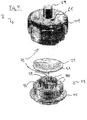
- Fig. 6 shows a schematic exploded view of another embodiment of a flushing device 7.
- a holding device described in more detail below is arranged.
- a bottom element 45 is inserted in the lower part 43 and has a support 47 for arranging a tooth cleaning mixture thereon.
- openings or passages 48 are formed in the support 47.
- a counter-pad 73 has openings 42 for the passage of liquid. When used, a tooth cleaning mixture is placed between the pad 47 and the counter pad 73
- a spring 71 is provided between the upper part 41 and the counter support 73. Between the bottom member 45 and the lower part 43, a spring 71 is also provided. The springs 69 and 71 provide the elastically biased arrangement of the tooth cleaning mixture.
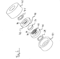
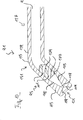
- Fig. 7 shows a schematic exploded view of another embodiment of a flushing device 7 with an upper part 41 and a lower part 43rd
- a swirl body 79 is provided in the rinsing chamber.
- the swirl body 79 is circular or cylindrical in shape and comprises in its side walls oblique recesses or through holes 81, is introduced through the liquid supplied in a vortex chamber 43 of the Verwirbelungs stressess 79.
- the oblique Zulauftbohrungen 81 cause additional turbulence.
- the swirling element 79 is mounted a holding device having inwardly extending (helical) support arms 49.
- the retaining arms 49 may be made of an elastically deformable and resilient material, such as plastic, fiberglass or similar materials.
- the holding arms 49 serve to receive and hold a tooth cleaning mixture (for example in the form of a tablet 21 or in a receiving structure 31).
- a grid or sieve structure 87 is provided, against which the tooth-cleaning mixture is forced by means of the holding arms 49.
- an outlet 61 is formed, can be derived through the cleaning suspension from the Aus Seriessch via a liquid discharge 9 to the outside.
- the turbulence element or the vertebral body 79 is arranged within the lower part 43.
- the holding device is placed or arranged either on or within the Verwirbelelements 79.
- the retaining arms 49 press in the composite Condition the dentifrice mixture against the screen structure 87, so provide the elatisch preloaded holder for a tooth cleaning mixture. This can be supported by a resilient configuration, the screen structure 87.
- liquid introduced into the rinsing device 7 flows via an inlet 63 in the lower part 43 into the rinsing-out chamber and is set there in rotation and swirling. Then, the liquid flows through the through-hole 81 into the swirling chamber 83 within the swirling body 79. From there, the swirling liquid flows through the holding arms 49 and flows around the tooth-cleaning mixture. In this case, the tooth cleaning mixture 21 is purged and dissolved particles, in particular abrasive components are guided by the liquid flow through the screen structure 87, and then discharged via the liquid outlet 61.
- the screen structure 87 may be firmly integrated within the upper part or else alternatively be made removable from the upper part.
- Fig. 8 shows a cross-sectional view of a nozzle 91 for the emission of tooth cleaning suspension.
- the nozzle 91 is connected at one of its ends to a fluid supply line 9 by means of a fastening element 95.
- the fastening element 95 can be designed as a fastening ring or clamp which urges the liquid line 9 against the nozzle 91.
- the nozzle 91 comprises a nozzle unit 93 housed in a sleeve 97.
- the sleeve 97 and the nozzle unit 93 are connected to each other, for example glued, welded, etc. Alternatively, these may also be integrally formed.
- a filter element 99 is arranged at the liquid supply line 9 facing the end of the nozzle unit 93.
- the filter element 99 comprises passages, for example boreholes or slots 101.
- a pressure chamber 103 lies downstream of the filter element 99. Within the pressure chamber 103 extends in the direction of the longitudinal axis 125 of the nozzle a fastening element 105, which is connected to the filter 99 or integrally formed thereon.
- a swirling agent in the form of a swirl body 107 is arranged at the opposite end of the fastener 105.
- the swirl body 107 runs conically in the flow direction.
- thread-like or spirally formed recesses 109 are formed between elevations 111.
- the recesses 109 and elevations 111 displace the flow into the nozzle 91.
- the liquid flows through the pressure chamber 103 and abuts on the flat end surface 107b of the swirl body 107. In this case, the liquid is deflected and flows around the edge regions of the swirl body 107th
- the nozzle unit 93 has housings 113.
- the housing 113 includes a substantially uniform ("linear") region that bounds the pressure chamber 103 and includes a portion of the swirler 107. Downstream of the housing 113 tapers to an outlet channel 117. Between the swirler 107 and the tapered housing walls 115 so a compression zone is formed.
- the outlet channel 117 runs in the direction of a nozzle mouth 121.
- the nozzle mouth or the outlet opening expands outward in the shape of a funnel.
- the slope of the slope can be 45 ° to the nozzle longitudinal axis 125.
- the nozzle mouth is formed in the manner of an outlet funnel.
- the nozzle mouth 121 runs flattened again, approximately at a 90 ° angle to the nozzle longitudinal axis 125 at surfaces 123.
- Swirling body 107 flowing liquid or suspension is twisted and accelerated, whereby the fluid pressure is increased.
- the channel 117 serves to further increase the pressure and turbulence of the liquid flow. In this case, liquid pressures of about 4 to 11 bar can be realized.
- the funnel-shaped widening 119 allows a hollow cone emerging liquid flow, wherein the widening of the liquid pressure is reduced.
- the flats 123 support a liquid jet concentric with the nozzle axis 125.
- Fig. 9 shows a further embodiment of a nozzle 91. This variant substantially compensates the embodiment Fig. 8 .
- a swirling agent here is a substantially cylindrical swirl body 107 is provided.
- Fig. 10 shows a perspective view of another embodiment of a nozzle 91.
- a liquid line 9 is arranged, which is coupled to a nozzle unit 93.
- the end of the nozzle unit 93 assigned to a nozzle opening or nozzle mouth 121 has a rounded bend or bend 131 in approximately one third of the total nozzle length.
- the bend 131 may be approximately 45 ° - 60 ° to the nozzle longitudinal axis 125. This causes a favorable positioning of the nozzle mouth 121, which allows a more ergonomic handling during the cleaning of teeth.
- the bend 131 affects the radiation behavior compared to a straight nozzle only insignificantly. In the oral field, hard-to-reach tooth areas can be reached as well.
- the bend 131 causes a tangential supply of the liquid flow to a swirler 107. This causes an additional rotation of the liquid flow.
- the swirl body 107 arranged in a cylindrically shaped portion reduces the volume of the cylindrical portion of a nozzle lumen so that the pressure of the liquid increases.
- the swirler 107 is funnel-shaped at its end to accelerate the liquid flow.
- the abrasive particles present in a suspension thus gain additional kinetic energy and acceleration.
- the inherent vibrations or oscillations of the nozzle body 91 prevent deposition of abrasive and non-water-soluble materials and particles from the suspension and thus, in particular, agglomeration and deposition due to the formation of neutr streams and dead zones. In particular, when using PMMA and rigid PVC usually no clogging of the nozzle 91 occur.
- the swirl body 107 has recesses 109 and elevations 111, which are designed here as trains and fields and are each offset by 120 ° and are divided symmetrically.
- a liquid flow enters the funnel-shaped inflowing pressure chamber 103.
- the funnel-shaped pressure chamber 103 opens at its output into a linear nozzle exit channel 117 of small diameter.
- the diameter may be, for example, 0.6 mm.
- the nozzle opening or the nozzle mouth 121 again comprises a mutually aligned outlet funnel, which is widened over funnel-shaped widening surfaces 119.
- the liquid stream is introduced into the liquid line approximately at an inlet pressure of 4 to 10 bar and corresponds approximately to the primary pressure in front of the nozzle.
- the nozzle 91 can be formed as a hollow cone nozzle. Such a design is particularly resistant to constipation. In addition, this embodiment causes a high dynamics of the liquid flow.
- a hollow cone nozzle reduces water consumption compared to full cones or full jet nozzles. Also, the liquid jet is amplified in the edge regions of the hollow cone, and thus increases the cleaning effect in comparison to a bundled liquid flow.
- the invention also relates to a rinsing tablet with abrasive components.
- a rinsing tablet with abrasive components For various applications in cleaning equipment, which act on objects to be cleaned with a cleansing water jet, the application of cleaning tablets, which dissolve in the rinse and jet water, is advantageous.
- Tableted detergents have a number of advantages over powdered ones: they are easier to dose and to handle and, due to their compact structure, have advantages in storage and transport.
- the pulverulent ingredients are generally mixed and then pressed into tablets or used as granules.
- a major cause of this problem is that high compression pressures must be used to produce sufficiently break-resistant tablets, resulting in a strong compaction of the tablets.
- tablet degradation agents may be described as materials which increase tablet dissolution rate in a cleaning medium.
- polymeric disintegrants for use herein include polymers that swell on contact with water, as well as those that facilitate water inflow and / or outflow by forming channels in the detergent tablet.
- Polymeric disintegrating agents for use herein include starch and cellulose and derivatives thereof, alginates, sugars, polyvinylpyrrolidones, among others.
- the invention is therefore intended to provide a composition of such rinsing tablets, which causes a more uniform resolution, avoids the cleaning of non-serving substances and avoids the whereabouts of insoluble residues in the rinsing and subsequent tubes, hoses and nozzles.
- magnesium oxide as an abrasive blasting agent in connection with cross-linked PVP.
- the former forms colorless crystals in the sodium chloride structure and is obtained from the thermal conversion of other magnesium compounds. It is often used in construction and food chemistry, e.g. as acidity regulator or release agent. It is approved in the EU as a food additive of the designation E 530 without quantitative limit (quantum satis) for food and is therefore suitable in contrast to some of the aforementioned components of cleaning tablets especially for dental care.
- a further blasting agent is used, which at the same time as.
- Disintegrating agent can be used for the controlled breaking up of the structure under the influence of water. This has been found in extensive trials in PVP used in multiple functions in tablets.
- Simple PVP linear polyvinylpyrrolidone
- vinylpyrrolidone is classified as a Category 3 carcinogen, the cross-linked polymer is considered safe for humans and is widely used in pharmacy (it is listed under the name crospovidone in En AB 6.0).
- the cross-linked variant Due to its swelling capacity, the cross-linked variant is suitable for targeted dissolution of the tablet pressed into the mold, as well as a further, gently abrasive blasting medium.
- the distribution is therefore gradual from the outer layer 60% MgO and completely inside 30% PVP, while the remaining 10% of the constituents bind and form such as e.g. Magnesium stearate and additives for each application included.
- the core of the tablet contains only 40% MgO and 50% PVP, which is associated with a faster dissolution of the tablet remainder with a - relative to the erosive amount of water - even proportion of abrasive elements, which avoids constipation.
- hydrophobic constituents such as finely divided silica.
- the rinsing tablet with abrasive constituents as constituents may consist of a mixture of magnesium oxide and crosslinked polyvinylpyrrolidone (PVP).
- the ratio of the components in different layers of the tablet may be different.
- the core in the rinsing tablet with abrasive constituents, can consist of only 40% MgO and 50% PVP.
- the outer layer in the rinsing tablet with abrasive constituents, can consist of 60% MgO and 30% PVP.
- hydrophobic moieties e.g. 1% fumed silica
- further medicinal, cosmetic or olfactory ingredients may be added to the rinse-off tablet containing abrasive components.
- the construction of a tablet comprises a core consisting of half of PVP and 40% of more abrasive MgO particles, a transition layer with a ratio of 50% MgO and 40% PVP, and an outer layer containing 60% MgO and only 30% PVP.
- the invention also relates to a system for dissolving a tablet or granules in a water stream, in particular to a water jet system in which media containing abrasive or abrading or abrasive constituents, in a so-called.
- a receiving structure such as for example, a fabric, mesh, mesh, or mesh structure of wire or plastic filament or fibers is wrapped so as to promote uniform dissolution and recollections that may clog filters and nozzles to avoid or prevent.
- tablets, powders or granules are used to deliver ingredients for cleaning or horticultural or processing purposes to a jet of water or stream.
- dissolution devices are used to hold the tablets or a powder through which a stream of water is passed, which gradually dissolves the media and directs the resulting suspension into a spray nozzle or the like.
- Partially dissolved components tend to recombine and clog filters and nozzles or orifices. This requires a careful selection of the constituent parts and often prevents a required concentration of a substance.
- abrasive media which tends to be the most compact element within the mixture, accumulates and clogs edge boundaries of constrictions as a result of their higher density and consequent resulting stronger centrifugal momentum or momentum in turbulence and due to their coarser surface.
- the containment structure provides a system of low but evenly distributed turbulence in the water flow around the containment structure so that the dissolution of the substance is fairly evenly enhanced, as long as there is adequate gap between the tablet or the powder surface is present. This distance is optimal at approximately 1/10 of the diameter of the tablet or powder surface.
- a recording structure or tissue, mesh, mesh or mesh size of about 0.3 mm leads to a good dissolution behavior, if the particle size is between about 4 and 6 mil, while the tablet has a diameter of about 30 mm and about 6 mm thick, with the distance between the receiving structure and the tablet at the top being approximately 3.0 mm.
- the voids within the receiving structure simply allow small particles of the abrasive media to pass through, with larger particle accumulations failing to meet the flow of one can reach aqueous mixture.
- depositing or remaining materials such as firmly bonded abrasive particles, can be held within the receiving structure and can be easily disposed of with the receiving structure after use.
- the invention relates to a tablet or granules comprising abrasive media, which are embedded in a flexible but sufficiently rigid receiving structure and are exposed to a flow of water that would dissolve soluble components and the detached abrasive particles in a stream of aqueous or carries away liquid mixture, whereby inevitably solidified residues can be disposed of with the receiving structure.
- the dissolution works well as long as the receiving structure is kept at a certain distance from the compressed tablet or tablets, or when granules are held sufficiently loosely within the receiving structure.
- the optimum shape has been found to be a disc-like receiving structure in which a tablet can flow in a vertical stream of water without rotating and straightening in the stream.
- a preferred embodiment of the invention is a disc-like receiving structure resulting from a double layer of a receiving structure and having a tablet or a small amount of granules therebetween, which is welded together around one To form edge of a few millimeters thick width, which is used as a storage area.
- abrasive components or components leads to a suspension flow or current in which particle accumulations or compounds do not exceed a size of 0.3 mm. This remains largely constant over the dissolution period as long as sufficient abrasive particles are present within the receiving structure.
- Recombinations that occur are retained within the containment structure and tend to re-entrain in the flow before they can clog filters and orifices. This helps to provide a substantially uniform concentration of media within the water stream, especially after the substance is ultimately reduced - this then typically forms a media cloud in the receiving structure which is eventually carried away relatively abruptly.
- a stream of suspension thus passed over the receiving structure will pass through curved nozzles (30 ° curvature at the nozzle point) without clogging due to the continuous flow pattern of the suspension.
- Residues that can not be dissolved and adherent clumps or agglomerations need not be removed by scraping them out of the dissolution device, but can easily be disposed of by simply opening and pivoting the unit to drop the receiving structure with any debris.
- a tablet contains abrasive particles and according to the invention is embedded or enveloped in a receiving structure, which consists of two panes or plate-like shells and which are formed by joining, in particular welding, a rim or edge of two parts of the receiving structure.
- a tablet or granule may be completely contained in a flexible but sufficiently stable containment structure, mesh, grid or net.
- a tablet or granules may comprise abrasive media along with other ingredients.
- the receiving structure can also be designed like a disk.
- the receiving structure is welded to form a border-like storage around the disc or disk.
- the recording structure thickness or mesh size does not exceed 0.3 mm.
- the thread or fabric wire diameter be between 0.12 mm and 0.25 mm.
- the receiving structure or the fabric structure is made of nylon or similar thermoplastic materials.
- the receiving structure or tissue is made of a bio-plastic, such as e.g. Cellulose Listereester or lactic acids.
- the flow of a water flow causes vibrations which enhance the dissolution and the discharge of abrasive media into the outflowing aqueous mixture.
- the receiving structure or the tissue structure or grid structure causes or causes a continuous delivery of abrasive media into the water, so that a homogeneous stream of an aqueous or liquid mixture is achieved becomes.
- the invention is intended to provide a rinsing chamber for cleaning tablets, which prevents known disadvantages such as deposits, blockages, etc., and ensures complete dissolution of a cleaning mixture.
- the tablet should always be rinsed on all sides, even if it shrinks due to the removal of the outer layers, without it breaking until the final phase.
- a rinsing chamber which supports an all-round rinsing of the tablet.
- the incoming stream of the medium is first mixed by a vortex chamber into turbulence.
- a uniform removal is achieved in that the tablet rests in front of a covering sieve on a finger-like, slightly spiral-shaped, elastic plastic holder.
- the tablet When inserting the tablet, it is slightly pressed into these and guided by the spiral fingers even with increasing reduction loosely against the sieve. Due to the swirling flow around, as well as the outgassing of the disintegrator, the tablet gets into vibration and rotates on the spiral fingers, so that the entire surface is wetted all around. This ensures that a steady and even with a defined amount of water complete removal of the components of the tablet.
- the water or media jet can enter through a lower nozzle in an inlet chamber of the rinsing chamber and is there by a
- Verwirbelungs with the passage from the outside by oblique holes introduced into the vortex chamber, on the finger-shaped recordings the cleaning tablet is placed. The thus flowing around them on all sides medium dissolves the tablet or on and enters through the vortex chamber final sieve in a transfer chamber and from there into an outlet.
- the medium entering the rinsing chamber can be set into turbulent-rotating motion by an upstream turbo-charger.
- the turbulator can consist of a cylinder which sets the medium to be conveyed into a rotating movement by segmenting bores in the cylinder wall.
- the bores in the turbulator can run horizontally and vertically at a 45 ° angle to the cylinder axis.
- the tablet can rest on a holder of spirally arranged, elastic plastic fingers.
- the outlet of the rinsing chamber can be closed by a sieve acting as a filter.
- the pressure of the medium flowing into the rinsing-out chamber can amount to between 4 and 10 bar for the uniform dissolution of cleaning tablets.
- a nozzle according to the invention for the emission of liquid cleaning agents having dispersed therein abrasive particles defined flexibility in order to deform on a microscopic scale so that the natural vibration during the passage of the medium with high pressure the addition of particles prevented their edges, or at short notice Abandoned again stored.
- the nozzle may include a turbulator that circularly swirls the medium, but has smooth walls on the compression chamber and in the nozzle passage, as well as a circular extension of 45 ° at the exit.
- the present invention is intended to inexpensively design nozzles to avoid clogging, even if their diameter is only slightly greater than the grain size of the solid components of the medium.
- the material of the nozzle must have a certain flexibility and can therefore be deformed on a microscopic scale, in order to prevent the accumulation of particles on their walls by the natural vibration when passing water with the appropriate pressure, or to temporarily replace stored goods again.
- the expensive conventional materials and expensive processing methods are unnecessary when the nozzles are e.g. made of plastic PMMA.
- these can be easily replaceable - and due to the low cost - if necessary, also be replaced.
- nozzles for water-dispersed, abrasive ingredients as described above at a primary pressure of 5 to 9 bar proved to be advantageous in which the functional areas vortex formation and beam guidance are designed so that the medium initially vortexed, but then in the compression and beam guidance as smooth walls as possible.
- a rotating turbulence is advantageous, which begins immediately before the compression zone and then a smooth beam guidance to the nozzle exit, which in turn is to take place at a 45 ° angle circular to the axis in the range of a material thickness of at least 0.5 mm.
- the invention allows a supply hose to the nozzle unit, which is taken in a sleeve, the medium entering through bores or slots in a filter plate in a pressure chamber where a held by a die, conical swirl body is enclosed by an analog conical housing and the medium in rotating turbulence pressed into an actual nozzle.
- the jet is widened again at the nozzle mouth.
- the swirl body may be cylindrically shaped and includes drill-like recesses for a rotating swirling of the medium, which enters the pressure chamber with the abrasives, which merges into the nozzle unit.
- the nozzle for blasting media with previously mixed abrasive ingredients at input pressures of 4 to 10 bar the nozzle made of semi-rigid plastics, such as polymethylmetalate (PMMA) or hard PVC exist.
- a spiral swirler may be arranged in the nozzle for blasting media with abrasive ingredients prior to entry of the media into the compression zone.
- the swirl body in the nozzle for blasting off media with abrasive ingredients, may have a conically narrowing shape at 15 ° to 25 ° to the axis.
- the spiral passage of the swirler may have about ( ⁇ 1) as many turns as its diameter is in millimeters at the thickest point.
- the compression zone behind the swirler may have a circular narrowing of the wall at an angle of 15 ° to 20 ° to the nozzle axis on both sides.
- the nozzle tube from the end of the compression zone to the expansion of the tailpipe at the outlet run straight.
- the nozzle mouth in the case of a nozzle for blasting off media containing abrasive constituents, can have a widening on both sides of 20 to 25 ° to the nozzle axis.
- the nozzle mouth in the case of a nozzle for emitting media with abrasive ingredients, can have a wall thickness of not more than 1 millimeter.
- the walls of the nozzle tube, the compression and outlet regions can be made smooth.
Landscapes
- Health & Medical Sciences (AREA)
- Engineering & Computer Science (AREA)
- Mechanical Engineering (AREA)
- Life Sciences & Earth Sciences (AREA)
- Dentistry (AREA)
- Epidemiology (AREA)
- Oral & Maxillofacial Surgery (AREA)
- Animal Behavior & Ethology (AREA)
- General Health & Medical Sciences (AREA)
- Public Health (AREA)
- Veterinary Medicine (AREA)
- Dental Tools And Instruments Or Auxiliary Dental Instruments (AREA)
- Cosmetics (AREA)
- Nozzles (AREA)
- Cleaning By Liquid Or Steam (AREA)
Applications Claiming Priority (4)
| Application Number | Priority Date | Filing Date | Title |
|---|---|---|---|
| DE102010051226A DE102010051226A1 (de) | 2010-11-12 | 2010-11-12 | Ausspültablete mit abrasiven Bestandteilen |
| DE102010051225A DE102010051225A1 (de) | 2010-11-12 | 2010-11-12 | Ausspülkammer für Reinigungstabletten |
| DE102010051227A DE102010051227A1 (de) | 2010-11-12 | 2010-11-12 | Düse zur Abstrahlung von flüssigen Reinigungsmitteln mit darin dispergierten abrasiven Partikeln |
| PCT/IB2011/000576 WO2012127257A1 (fr) | 2011-03-19 | 2011-03-19 | Système pour dissolution d'une pastille ou d'un granulé dans un courant d'eau |
Publications (3)
| Publication Number | Publication Date |
|---|---|
| EP2452780A2 true EP2452780A2 (fr) | 2012-05-16 |
| EP2452780A3 EP2452780A3 (fr) | 2012-11-07 |
| EP2452780B1 EP2452780B1 (fr) | 2015-01-07 |
Family
ID=44925244
Family Applications (1)
| Application Number | Title | Priority Date | Filing Date |
|---|---|---|---|
| EP11009002.4A Active EP2452780B1 (fr) | 2010-11-12 | 2011-11-11 | Système pour nettoyer les dents |
Country Status (3)
| Country | Link |
|---|---|
| US (1) | US9566130B2 (fr) |
| EP (1) | EP2452780B1 (fr) |
| ES (1) | ES2536848T3 (fr) |
Cited By (4)
| Publication number | Priority date | Publication date | Assignee | Title |
|---|---|---|---|---|
| EP2868292A1 (fr) * | 2013-10-29 | 2015-05-06 | Bruni Binyamin Cohen Tanugi | Applicateur destiné à distribuer des matériaux à travers un dispositif de jet d'eau |
| WO2019084633A1 (fr) * | 2017-11-03 | 2019-05-09 | Rivus Ood | Buse pour économie d'eau |
| EP3530355A1 (fr) * | 2018-02-27 | 2019-08-28 | Albéa Services | Tête de distribution à chambre tourbillonnaire étagée pour un système de distribution |
| CN112754708A (zh) * | 2021-01-15 | 2021-05-07 | 云南白药集团健康产品有限公司 | 一种便携式气压自喷水牙线 |
Families Citing this family (29)
| Publication number | Priority date | Publication date | Assignee | Title |
|---|---|---|---|---|
| US10835355B2 (en) | 2006-04-20 | 2020-11-17 | Sonendo, Inc. | Apparatus and methods for treating root canals of teeth |
| US8753121B2 (en) | 2006-04-20 | 2014-06-17 | Sonendo, Inc. | Apparatus and methods for treating root canals of teeth |
| US7980854B2 (en) | 2006-08-24 | 2011-07-19 | Medical Dental Advanced Technologies Group, L.L.C. | Dental and medical treatments and procedures |
| US12114924B2 (en) | 2006-08-24 | 2024-10-15 | Pipstek, Llc | Treatment system and method |
| EP3384870B1 (fr) | 2009-11-13 | 2020-12-23 | Sonendo, Inc. | Appareil à jet de liquide pour des traitements dentaires |
| CA2815219A1 (fr) | 2010-10-21 | 2012-04-26 | Sonendo, Inc. | Appareil, procedes et compositions pour traitements endodontiques |
| IN2014DN08727A (fr) | 2012-03-22 | 2015-05-22 | Sonendo Inc | |
| US10631962B2 (en) | 2012-04-13 | 2020-04-28 | Sonendo, Inc. | Apparatus and methods for cleaning teeth and gingival pockets |
| IL219169A0 (en) | 2012-04-15 | 2012-07-31 | Yehuda Darshan | Apparatus for cleaning tissues from root canal by spinning liquid jet |
| US10363120B2 (en) | 2012-12-20 | 2019-07-30 | Sonendo, Inc. | Apparatus and methods for cleaning teeth and root canals |
| EP3943042B1 (fr) | 2012-12-20 | 2024-03-13 | Sonendo, Inc. | Appareil de nettoyage de dents et de canaux radiculaires |
| EP3581384B1 (fr) | 2013-02-04 | 2021-04-14 | Sonendo, Inc. | Système de traitement dentaire |
| US10722325B2 (en) | 2013-05-01 | 2020-07-28 | Sonendo, Inc. | Apparatus and methods for treating teeth |
| US9055989B2 (en) * | 2013-05-14 | 2015-06-16 | Arthur Kitchings Weathers | Low-splash reducing implement for dental applications |
| JP6417596B2 (ja) * | 2013-06-05 | 2018-11-07 | 株式会社サンギ | 粉体噴射用ハンドピース |
| US9877801B2 (en) | 2013-06-26 | 2018-01-30 | Sonendo, Inc. | Apparatus and methods for filling teeth and root canals |
| US10849726B2 (en) * | 2013-11-21 | 2020-12-01 | Koninklijke Philips N.V. | Air-driven interproximal toothbrush |
| JP6284222B2 (ja) * | 2013-11-28 | 2018-02-28 | 株式会社サンギ | 粉体流通装置 |
| WO2015153297A1 (fr) * | 2014-04-02 | 2015-10-08 | David Roberts | Pointe d'hydropulseur ayant un récipient pour des comprimés de traitement |
| US10806544B2 (en) | 2016-04-04 | 2020-10-20 | Sonendo, Inc. | Systems and methods for removing foreign objects from root canals |
| GB2555449B (en) * | 2016-10-28 | 2020-04-22 | Dyson Technology Ltd | Cleaning appliance |
| USD825741S1 (en) | 2016-12-15 | 2018-08-14 | Water Pik, Inc. | Oral irrigator handle |
| CA3051863C (fr) * | 2017-02-02 | 2023-12-19 | Water Pik, Inc. | Comprimes de nettoyage dentaire contenant de la glycine comme abrasif |
| CN110730641B (zh) | 2017-03-16 | 2022-03-25 | 洁碧有限公司 | 用于与口腔试剂一起使用的口腔冲洗器手柄 |
| JP2020075303A (ja) * | 2018-11-05 | 2020-05-21 | 櫻護謨株式会社 | ノズルおよびブラスト装置 |
| WO2022070133A1 (fr) * | 2020-09-30 | 2022-04-07 | Nigel Richard Farrow | Insert destiné à être utilisé dans le traitement au jet à sec |
| USD997355S1 (en) | 2020-10-07 | 2023-08-29 | Sonendo, Inc. | Dental treatment instrument |
| CN115105234B (zh) * | 2022-06-27 | 2024-06-21 | 广东罗曼智能科技股份有限公司 | 一种可托载泡腾球滚动的冲牙器用喷嘴 |
| USD1118938S1 (en) | 2022-09-23 | 2026-03-17 | Sonendo, Inc. | Dental console |
Family Cites Families (15)
| Publication number | Priority date | Publication date | Assignee | Title |
|---|---|---|---|---|
| US2024146A (en) * | 1934-01-03 | 1935-12-17 | Herl L Crowther | Dentifrice and method of making same |
| CH354895A (de) * | 1956-02-13 | 1961-06-15 | Maurer Jakob | Vorrichtung zum Bearbeiten der Zähne im Munde |
| US3386439A (en) * | 1965-10-19 | 1968-06-04 | Thomas P. Harper | Dental irrigator |
| US3566863A (en) * | 1969-05-01 | 1971-03-02 | Richard D Law | Gas-pressurized washing device |
| US4214871A (en) * | 1978-01-23 | 1980-07-29 | Arnold Carter H | Method and apparatus for cleaning teeth and removing plaque |
| US4540365A (en) * | 1983-11-23 | 1985-09-10 | Advanced Design Corporation | Dental cleansing system |
| US4564005A (en) * | 1983-12-05 | 1986-01-14 | Marchand Paul A | Oral irrigating device |
| WO1988001839A1 (fr) * | 1986-09-08 | 1988-03-24 | Ginebre Frederic | Brosse a dents |
| US4978297A (en) * | 1989-09-19 | 1990-12-18 | Vlock D G | Handpiece with additive chamber |
| SE8903563D0 (sv) * | 1989-10-26 | 1989-10-26 | Haessle Ab | A novel dissolution system |
| EP0691183B1 (fr) * | 1994-07-08 | 1999-09-15 | Dr. Hartmann-Kulba Bauchemie GmbH & Co. KG | Buse à jet utilisée dans des dispositifs pour le nettoyage notamment des surfaces de pierre et/ou métalliques |
| NO313614B1 (no) * | 2000-08-08 | 2002-11-04 | Per Hoeiby | Anordning for tannpleie |
| EP1639913B1 (fr) * | 2004-09-22 | 2011-11-23 | Trisa Holding AG | Brosse, notamment brosse à dents et procédé de fabrication |
| WO2008046580A1 (fr) * | 2006-10-16 | 2008-04-24 | Gimelli Produktions Ag | Douchette buccale avec un dispositif pour mélanger des additifs à l'eau |
| EP2515784A1 (fr) | 2009-12-08 | 2012-10-31 | Daniel Mueller | Dispositif de nettoyage dentaire |
-
2011
- 2011-11-11 US US13/294,837 patent/US9566130B2/en active Active
- 2011-11-11 EP EP11009002.4A patent/EP2452780B1/fr active Active
- 2011-11-11 ES ES11009002.4T patent/ES2536848T3/es active Active
Non-Patent Citations (1)
| Title |
|---|
| None |
Cited By (5)
| Publication number | Priority date | Publication date | Assignee | Title |
|---|---|---|---|---|
| EP2868292A1 (fr) * | 2013-10-29 | 2015-05-06 | Bruni Binyamin Cohen Tanugi | Applicateur destiné à distribuer des matériaux à travers un dispositif de jet d'eau |
| WO2019084633A1 (fr) * | 2017-11-03 | 2019-05-09 | Rivus Ood | Buse pour économie d'eau |
| EP3530355A1 (fr) * | 2018-02-27 | 2019-08-28 | Albéa Services | Tête de distribution à chambre tourbillonnaire étagée pour un système de distribution |
| FR3078271A1 (fr) * | 2018-02-27 | 2019-08-30 | Albea Services | Tete de distribution a chambre tourbillonnaire etagee pour un systeme de distribution |
| CN112754708A (zh) * | 2021-01-15 | 2021-05-07 | 云南白药集团健康产品有限公司 | 一种便携式气压自喷水牙线 |
Also Published As
| Publication number | Publication date |
|---|---|
| EP2452780B1 (fr) | 2015-01-07 |
| US20120141953A1 (en) | 2012-06-07 |
| ES2536848T3 (es) | 2015-05-29 |
| US9566130B2 (en) | 2017-02-14 |
| EP2452780A3 (fr) | 2012-11-07 |
Similar Documents
| Publication | Publication Date | Title |
|---|---|---|
| EP2452780B1 (fr) | Système pour nettoyer les dents | |
| DE69634237T2 (de) | Dosiervorrichtung für pulverförmige medikamente | |
| EP0157121B1 (fr) | Récipient pour distribuer des pâtes dentaires | |
| EP0958792B1 (fr) | Outil manuel médical ou dentaire | |
| EP1099470B1 (fr) | Dispositif pour mélanger deux matières pâteuses, en particulier pour mélanger une matière pour empreinte dentaire avec une matière de calalyse | |
| EP3083088B1 (fr) | Cartouche de nettoyage pour dispositif de nettoyage dans un four | |
| EP0828902B2 (fr) | Recipient permettant de distribuer des preparations de principes actifs liquides ou pateuses dans des w-c | |
| EP2888418A1 (fr) | Panier pour toilettes à débit de produit variable | |
| EP3482713A1 (fr) | Partie a buse pour appareil a jet de poudre dentaire | |
| EP0182983B1 (fr) | Appareil pour enlever la plaque et les changements de couleur sur les surfaces dentaires | |
| WO2006136215A2 (fr) | Systeme d'acheminement de l'eau de chasse d'eau pour cuvette de w-c | |
| WO2008046580A1 (fr) | Douchette buccale avec un dispositif pour mélanger des additifs à l'eau | |
| EP1569574A2 (fr) | Canule con ue pour une piece a main medicale ou medico-dentaire pour pulveriser une substance d'ecoulement abrasive | |
| EP1243227B1 (fr) | Tête de buse pour un appareil dentaire à jet abrasif | |
| WO1990003217A1 (fr) | Dispositif pour la granulation d'une matiere plastique moulable ne s'ecoulant pas par gravite et pour l'utilisation d'une extrudeuse | |
| DE4102182C2 (de) | Vorrichtung zum Einbringen eines Pflegemittels in ein Absaugsystem, insbesondere in ein zahnärztliches Absaugsystem | |
| EP2536533B1 (fr) | Système pour dissolution d'une pastille ou d'un granulé dentaire dans un courant d'eau | |
| DE2731944A1 (de) | Filterelement | |
| WO1982002150A1 (fr) | Dispositif pour l'epuration des eaux | |
| DE29917937U1 (de) | Wasserleitungs - Fremdmaterialverstopfungs - Entfernungsvorrichtung | |
| EP0646679B1 (fr) | Filtre pour robinets d'eau | |
| EP1161293A2 (fr) | Dispositif de nettoyage | |
| DE202009013692U1 (de) | Handbrause | |
| DE102005047812A1 (de) | Verfahren zur Behandlung von Staub in einem Staubsammelbehälter und Vorrichtung zur Durchführung eines solchen Verfahrens | |
| DE102015215595B4 (de) | Steckelement und Milchaufschäumeinrichtung |
Legal Events
| Date | Code | Title | Description |
|---|---|---|---|
| PUAI | Public reference made under article 153(3) epc to a published international application that has entered the european phase |
Free format text: ORIGINAL CODE: 0009012 |
|
| AK | Designated contracting states |
Kind code of ref document: A2 Designated state(s): AL AT BE BG CH CY CZ DE DK EE ES FI FR GB GR HR HU IE IS IT LI LT LU LV MC MK MT NL NO PL PT RO RS SE SI SK SM TR |
|
| AX | Request for extension of the european patent |
Extension state: BA ME |
|
| RIC1 | Information provided on ipc code assigned before grant |
Ipc: C11D 17/04 20060101ALI20120625BHEP Ipc: D06F 39/02 20060101ALI20120625BHEP Ipc: A61C 3/025 20060101ALI20120625BHEP Ipc: B24C 7/00 20060101AFI20120625BHEP Ipc: B05B 1/34 20060101ALI20120625BHEP |
|
| PUAL | Search report despatched |
Free format text: ORIGINAL CODE: 0009013 |
|
| AK | Designated contracting states |
Kind code of ref document: A3 Designated state(s): AL AT BE BG CH CY CZ DE DK EE ES FI FR GB GR HR HU IE IS IT LI LT LU LV MC MK MT NL NO PL PT RO RS SE SI SK SM TR |
|
| AX | Request for extension of the european patent |
Extension state: BA ME |
|
| RIC1 | Information provided on ipc code assigned before grant |
Ipc: A61C 3/025 20060101ALI20121002BHEP Ipc: B24C 7/00 20060101AFI20121002BHEP Ipc: B05B 1/34 20060101ALI20121002BHEP Ipc: D06F 39/02 20060101ALI20121002BHEP Ipc: C11D 17/04 20060101ALI20121002BHEP |
|
| 17P | Request for examination filed |
Effective date: 20130507 |
|
| RBV | Designated contracting states (corrected) |
Designated state(s): AL AT BE BG CH CY CZ DE DK EE ES FI FR GB GR HR HU IE IS IT LI LT LU LV MC MK MT NL NO PL PT RO RS SE SI SK SM TR |
|
| 17Q | First examination report despatched |
Effective date: 20130930 |
|
| GRAP | Despatch of communication of intention to grant a patent |
Free format text: ORIGINAL CODE: EPIDOSNIGR1 |
|
| INTG | Intention to grant announced |
Effective date: 20140602 |
|
| GRAS | Grant fee paid |
Free format text: ORIGINAL CODE: EPIDOSNIGR3 |
|
| RAP1 | Party data changed (applicant data changed or rights of an application transferred) |
Owner name: DENTAL CARE INNOVATION GMBH |
|
| GRAA | (expected) grant |
Free format text: ORIGINAL CODE: 0009210 |
|
| AK | Designated contracting states |
Kind code of ref document: B1 Designated state(s): AL AT BE BG CH CY CZ DE DK EE ES FI FR GB GR HR HU IE IS IT LI LT LU LV MC MK MT NL NO PL PT RO RS SE SI SK SM TR |
|
| REG | Reference to a national code |
Ref country code: GB Ref legal event code: FG4D Free format text: NOT ENGLISH |
|
| REG | Reference to a national code |
Ref country code: CH Ref legal event code: EP |
|
| REG | Reference to a national code |
Ref country code: IE Ref legal event code: FG4D Free format text: LANGUAGE OF EP DOCUMENT: GERMAN |
|
| REG | Reference to a national code |
Ref country code: AT Ref legal event code: REF Ref document number: 705352 Country of ref document: AT Kind code of ref document: T Effective date: 20150215 |
|
| REG | Reference to a national code |
Ref country code: DE Ref legal event code: R096 Ref document number: 502011005518 Country of ref document: DE Effective date: 20150219 |
|
| REG | Reference to a national code |
Ref country code: ES Ref legal event code: FG2A Ref document number: 2536848 Country of ref document: ES Kind code of ref document: T3 Effective date: 20150529 |
|
| REG | Reference to a national code |
Ref country code: LT Ref legal event code: MG4D |
|
| REG | Reference to a national code |
Ref country code: CH Ref legal event code: NV Representative=s name: E. BLUM AND CO. AG PATENT- UND MARKENANWAELTE , CH |
|
| PG25 | Lapsed in a contracting state [announced via postgrant information from national office to epo] |
Ref country code: NO Free format text: LAPSE BECAUSE OF FAILURE TO SUBMIT A TRANSLATION OF THE DESCRIPTION OR TO PAY THE FEE WITHIN THE PRESCRIBED TIME-LIMIT Effective date: 20150407 Ref country code: HR Free format text: LAPSE BECAUSE OF FAILURE TO SUBMIT A TRANSLATION OF THE DESCRIPTION OR TO PAY THE FEE WITHIN THE PRESCRIBED TIME-LIMIT Effective date: 20150107 Ref country code: BG Free format text: LAPSE BECAUSE OF FAILURE TO SUBMIT A TRANSLATION OF THE DESCRIPTION OR TO PAY THE FEE WITHIN THE PRESCRIBED TIME-LIMIT Effective date: 20150407 Ref country code: SE Free format text: LAPSE BECAUSE OF FAILURE TO SUBMIT A TRANSLATION OF THE DESCRIPTION OR TO PAY THE FEE WITHIN THE PRESCRIBED TIME-LIMIT Effective date: 20150107 Ref country code: FI Free format text: LAPSE BECAUSE OF FAILURE TO SUBMIT A TRANSLATION OF THE DESCRIPTION OR TO PAY THE FEE WITHIN THE PRESCRIBED TIME-LIMIT Effective date: 20150107 Ref country code: LT Free format text: LAPSE BECAUSE OF FAILURE TO SUBMIT A TRANSLATION OF THE DESCRIPTION OR TO PAY THE FEE WITHIN THE PRESCRIBED TIME-LIMIT Effective date: 20150107 |
|
| PG25 | Lapsed in a contracting state [announced via postgrant information from national office to epo] |
Ref country code: PL Free format text: LAPSE BECAUSE OF FAILURE TO SUBMIT A TRANSLATION OF THE DESCRIPTION OR TO PAY THE FEE WITHIN THE PRESCRIBED TIME-LIMIT Effective date: 20150107 Ref country code: LV Free format text: LAPSE BECAUSE OF FAILURE TO SUBMIT A TRANSLATION OF THE DESCRIPTION OR TO PAY THE FEE WITHIN THE PRESCRIBED TIME-LIMIT Effective date: 20150107 Ref country code: IS Free format text: LAPSE BECAUSE OF FAILURE TO SUBMIT A TRANSLATION OF THE DESCRIPTION OR TO PAY THE FEE WITHIN THE PRESCRIBED TIME-LIMIT Effective date: 20150507 Ref country code: RS Free format text: LAPSE BECAUSE OF FAILURE TO SUBMIT A TRANSLATION OF THE DESCRIPTION OR TO PAY THE FEE WITHIN THE PRESCRIBED TIME-LIMIT Effective date: 20150107 Ref country code: GR Free format text: LAPSE BECAUSE OF FAILURE TO SUBMIT A TRANSLATION OF THE DESCRIPTION OR TO PAY THE FEE WITHIN THE PRESCRIBED TIME-LIMIT Effective date: 20150408 |
|
| REG | Reference to a national code |
Ref country code: FR Ref legal event code: PLFP Year of fee payment: 5 Ref country code: DE Ref legal event code: R097 Ref document number: 502011005518 Country of ref document: DE |
|
| PG25 | Lapsed in a contracting state [announced via postgrant information from national office to epo] |
Ref country code: CZ Free format text: LAPSE BECAUSE OF FAILURE TO SUBMIT A TRANSLATION OF THE DESCRIPTION OR TO PAY THE FEE WITHIN THE PRESCRIBED TIME-LIMIT Effective date: 20150107 Ref country code: SK Free format text: LAPSE BECAUSE OF FAILURE TO SUBMIT A TRANSLATION OF THE DESCRIPTION OR TO PAY THE FEE WITHIN THE PRESCRIBED TIME-LIMIT Effective date: 20150107 Ref country code: RO Free format text: LAPSE BECAUSE OF FAILURE TO SUBMIT A TRANSLATION OF THE DESCRIPTION OR TO PAY THE FEE WITHIN THE PRESCRIBED TIME-LIMIT Effective date: 20150107 Ref country code: EE Free format text: LAPSE BECAUSE OF FAILURE TO SUBMIT A TRANSLATION OF THE DESCRIPTION OR TO PAY THE FEE WITHIN THE PRESCRIBED TIME-LIMIT Effective date: 20150107 Ref country code: DK Free format text: LAPSE BECAUSE OF FAILURE TO SUBMIT A TRANSLATION OF THE DESCRIPTION OR TO PAY THE FEE WITHIN THE PRESCRIBED TIME-LIMIT Effective date: 20150107 |
|
| PLBE | No opposition filed within time limit |
Free format text: ORIGINAL CODE: 0009261 |
|
| STAA | Information on the status of an ep patent application or granted ep patent |
Free format text: STATUS: NO OPPOSITION FILED WITHIN TIME LIMIT |
|
| 26N | No opposition filed |
Effective date: 20151008 |
|
| PG25 | Lapsed in a contracting state [announced via postgrant information from national office to epo] |
Ref country code: SI Free format text: LAPSE BECAUSE OF FAILURE TO SUBMIT A TRANSLATION OF THE DESCRIPTION OR TO PAY THE FEE WITHIN THE PRESCRIBED TIME-LIMIT Effective date: 20150107 |
|
| PG25 | Lapsed in a contracting state [announced via postgrant information from national office to epo] |
Ref country code: MC Free format text: LAPSE BECAUSE OF FAILURE TO SUBMIT A TRANSLATION OF THE DESCRIPTION OR TO PAY THE FEE WITHIN THE PRESCRIBED TIME-LIMIT Effective date: 20150107 Ref country code: LU Free format text: LAPSE BECAUSE OF FAILURE TO SUBMIT A TRANSLATION OF THE DESCRIPTION OR TO PAY THE FEE WITHIN THE PRESCRIBED TIME-LIMIT Effective date: 20151111 |
|
| REG | Reference to a national code |
Ref country code: IE Ref legal event code: MM4A |
|
| REG | Reference to a national code |
Ref country code: FR Ref legal event code: PLFP Year of fee payment: 6 |
|
| PG25 | Lapsed in a contracting state [announced via postgrant information from national office to epo] |
Ref country code: IE Free format text: LAPSE BECAUSE OF NON-PAYMENT OF DUE FEES Effective date: 20151111 |
|
| PG25 | Lapsed in a contracting state [announced via postgrant information from national office to epo] |
Ref country code: HU Free format text: LAPSE BECAUSE OF FAILURE TO SUBMIT A TRANSLATION OF THE DESCRIPTION OR TO PAY THE FEE WITHIN THE PRESCRIBED TIME-LIMIT; INVALID AB INITIO Effective date: 20111111 Ref country code: SM Free format text: LAPSE BECAUSE OF FAILURE TO SUBMIT A TRANSLATION OF THE DESCRIPTION OR TO PAY THE FEE WITHIN THE PRESCRIBED TIME-LIMIT Effective date: 20150107 |
|
| PG25 | Lapsed in a contracting state [announced via postgrant information from national office to epo] |
Ref country code: CY Free format text: LAPSE BECAUSE OF FAILURE TO SUBMIT A TRANSLATION OF THE DESCRIPTION OR TO PAY THE FEE WITHIN THE PRESCRIBED TIME-LIMIT Effective date: 20150107 |
|
| PG25 | Lapsed in a contracting state [announced via postgrant information from national office to epo] |
Ref country code: BE Free format text: LAPSE BECAUSE OF NON-PAYMENT OF DUE FEES Effective date: 20151130 |
|
| PG25 | Lapsed in a contracting state [announced via postgrant information from national office to epo] |
Ref country code: TR Free format text: LAPSE BECAUSE OF FAILURE TO SUBMIT A TRANSLATION OF THE DESCRIPTION OR TO PAY THE FEE WITHIN THE PRESCRIBED TIME-LIMIT Effective date: 20150107 Ref country code: MT Free format text: LAPSE BECAUSE OF FAILURE TO SUBMIT A TRANSLATION OF THE DESCRIPTION OR TO PAY THE FEE WITHIN THE PRESCRIBED TIME-LIMIT Effective date: 20150107 |
|
| REG | Reference to a national code |
Ref country code: FR Ref legal event code: PLFP Year of fee payment: 7 |
|
| REG | Reference to a national code |
Ref country code: AT Ref legal event code: MM01 Ref document number: 705352 Country of ref document: AT Kind code of ref document: T Effective date: 20161111 |
|
| PG25 | Lapsed in a contracting state [announced via postgrant information from national office to epo] |
Ref country code: AT Free format text: LAPSE BECAUSE OF NON-PAYMENT OF DUE FEES Effective date: 20161111 |
|
| PG25 | Lapsed in a contracting state [announced via postgrant information from national office to epo] |
Ref country code: PT Free format text: LAPSE BECAUSE OF FAILURE TO SUBMIT A TRANSLATION OF THE DESCRIPTION OR TO PAY THE FEE WITHIN THE PRESCRIBED TIME-LIMIT Effective date: 20150107 Ref country code: MK Free format text: LAPSE BECAUSE OF FAILURE TO SUBMIT A TRANSLATION OF THE DESCRIPTION OR TO PAY THE FEE WITHIN THE PRESCRIBED TIME-LIMIT Effective date: 20150107 |
|
| REG | Reference to a national code |
Ref country code: FR Ref legal event code: PLFP Year of fee payment: 8 |
|
| PG25 | Lapsed in a contracting state [announced via postgrant information from national office to epo] |
Ref country code: AL Free format text: LAPSE BECAUSE OF FAILURE TO SUBMIT A TRANSLATION OF THE DESCRIPTION OR TO PAY THE FEE WITHIN THE PRESCRIBED TIME-LIMIT Effective date: 20150107 |
|
| PGFP | Annual fee paid to national office [announced via postgrant information from national office to epo] |
Ref country code: NL Payment date: 20230915 Year of fee payment: 13 |
|
| PGFP | Annual fee paid to national office [announced via postgrant information from national office to epo] |
Ref country code: ES Payment date: 20231211 Year of fee payment: 13 |
|
| PGFP | Annual fee paid to national office [announced via postgrant information from national office to epo] |
Ref country code: IT Payment date: 20231010 Year of fee payment: 13 |
|
| PGFP | Annual fee paid to national office [announced via postgrant information from national office to epo] |
Ref country code: CH Payment date: 20240127 Year of fee payment: 13 |
|
| PGFP | Annual fee paid to national office [announced via postgrant information from national office to epo] |
Ref country code: FR Payment date: 20240909 Year of fee payment: 14 |
|
| PGFP | Annual fee paid to national office [announced via postgrant information from national office to epo] |
Ref country code: DE Payment date: 20241224 Year of fee payment: 14 |
|
| PGFP | Annual fee paid to national office [announced via postgrant information from national office to epo] |
Ref country code: GB Payment date: 20241227 Year of fee payment: 14 |
|
| REG | Reference to a national code |
Ref country code: CH Ref legal event code: PL |
|
| REG | Reference to a national code |
Ref country code: NL Ref legal event code: MM Effective date: 20241201 |
|
| REG | Reference to a national code |
Ref country code: CH Ref legal event code: PL |
|
| PG25 | Lapsed in a contracting state [announced via postgrant information from national office to epo] |
Ref country code: CH Free format text: LAPSE BECAUSE OF NON-PAYMENT OF DUE FEES Effective date: 20241130 |
|
| PG25 | Lapsed in a contracting state [announced via postgrant information from national office to epo] |
Ref country code: NL Free format text: LAPSE BECAUSE OF NON-PAYMENT OF DUE FEES Effective date: 20241201 |
|
| PG25 | Lapsed in a contracting state [announced via postgrant information from national office to epo] |
Ref country code: IT Free format text: LAPSE BECAUSE OF NON-PAYMENT OF DUE FEES Effective date: 20241111 |
|
| REG | Reference to a national code |
Ref country code: ES Ref legal event code: FD2A Effective date: 20260102 |
|
| PG25 | Lapsed in a contracting state [announced via postgrant information from national office to epo] |
Ref country code: ES Free format text: LAPSE BECAUSE OF NON-PAYMENT OF DUE FEES Effective date: 20241112 |