EP2452888B1 - Gegen innere Kräfte beständiger Verpackungsverschluss - Google Patents
Gegen innere Kräfte beständiger Verpackungsverschluss Download PDFInfo
- Publication number
- EP2452888B1 EP2452888B1 EP12154536.2A EP12154536A EP2452888B1 EP 2452888 B1 EP2452888 B1 EP 2452888B1 EP 12154536 A EP12154536 A EP 12154536A EP 2452888 B1 EP2452888 B1 EP 2452888B1
- Authority
- EP
- European Patent Office
- Prior art keywords
- bag
- slider
- panels
- closure assembly
- subject matter
- Prior art date
- Legal status (The legal status is an assumption and is not a legal conclusion. Google has not performed a legal analysis and makes no representation as to the accuracy of the status listed.)
- Active
Links
Images





Classifications
-
- B—PERFORMING OPERATIONS; TRANSPORTING
- B65—CONVEYING; PACKING; STORING; HANDLING THIN OR FILAMENTARY MATERIAL
- B65B—MACHINES, APPARATUS OR DEVICES FOR, OR METHODS OF, PACKAGING ARTICLES OR MATERIALS; UNPACKING
- B65B7/00—Closing containers or receptacles after filling
- B65B7/02—Closing containers or receptacles deformed by, or taking-up shape, of, contents, e.g. bags, sacks
-
- B—PERFORMING OPERATIONS; TRANSPORTING
- B65—CONVEYING; PACKING; STORING; HANDLING THIN OR FILAMENTARY MATERIAL
- B65D—CONTAINERS FOR STORAGE OR TRANSPORT OF ARTICLES OR MATERIALS, e.g. BAGS, BARRELS, BOTTLES, BOXES, CANS, CARTONS, CRATES, DRUMS, JARS, TANKS, HOPPERS, FORWARDING CONTAINERS; ACCESSORIES, CLOSURES, OR FITTINGS THEREFOR; PACKAGING ELEMENTS; PACKAGES
- B65D33/00—Details of, or accessories for, sacks or bags
- B65D33/16—End- or aperture-closing arrangements or devices
- B65D33/25—Riveting; Dovetailing; Screwing; using press buttons or slide fasteners
- B65D33/2508—Riveting; Dovetailing; Screwing; using press buttons or slide fasteners using slide fasteners with interlocking members having a substantially uniform section throughout the length of the fastener; Sliders therefor
-
- B—PERFORMING OPERATIONS; TRANSPORTING
- B65—CONVEYING; PACKING; STORING; HANDLING THIN OR FILAMENTARY MATERIAL
- B65D—CONTAINERS FOR STORAGE OR TRANSPORT OF ARTICLES OR MATERIALS, e.g. BAGS, BARRELS, BOTTLES, BOXES, CANS, CARTONS, CRATES, DRUMS, JARS, TANKS, HOPPERS, FORWARDING CONTAINERS; ACCESSORIES, CLOSURES, OR FITTINGS THEREFOR; PACKAGING ELEMENTS; PACKAGES
- B65D33/00—Details of, or accessories for, sacks or bags
- B65D33/16—End- or aperture-closing arrangements or devices
- B65D33/25—Riveting; Dovetailing; Screwing; using press buttons or slide fasteners
- B65D33/2508—Riveting; Dovetailing; Screwing; using press buttons or slide fasteners using slide fasteners with interlocking members having a substantially uniform section throughout the length of the fastener; Sliders therefor
- B65D33/2516—Riveting; Dovetailing; Screwing; using press buttons or slide fasteners using slide fasteners with interlocking members having a substantially uniform section throughout the length of the fastener; Sliders therefor comprising tamper-indicating means, e.g. located within the fastener
- B65D33/2525—Riveting; Dovetailing; Screwing; using press buttons or slide fasteners using slide fasteners with interlocking members having a substantially uniform section throughout the length of the fastener; Sliders therefor comprising tamper-indicating means, e.g. located within the fastener located between the fastener and the product compartment
-
- B—PERFORMING OPERATIONS; TRANSPORTING
- B65—CONVEYING; PACKING; STORING; HANDLING THIN OR FILAMENTARY MATERIAL
- B65D—CONTAINERS FOR STORAGE OR TRANSPORT OF ARTICLES OR MATERIALS, e.g. BAGS, BARRELS, BOTTLES, BOXES, CANS, CARTONS, CRATES, DRUMS, JARS, TANKS, HOPPERS, FORWARDING CONTAINERS; ACCESSORIES, CLOSURES, OR FITTINGS THEREFOR; PACKAGING ELEMENTS; PACKAGES
- B65D33/00—Details of, or accessories for, sacks or bags
- B65D33/16—End- or aperture-closing arrangements or devices
- B65D33/25—Riveting; Dovetailing; Screwing; using press buttons or slide fasteners
- B65D33/2508—Riveting; Dovetailing; Screwing; using press buttons or slide fasteners using slide fasteners with interlocking members having a substantially uniform section throughout the length of the fastener; Sliders therefor
- B65D33/2584—Riveting; Dovetailing; Screwing; using press buttons or slide fasteners using slide fasteners with interlocking members having a substantially uniform section throughout the length of the fastener; Sliders therefor characterized by the slider
- B65D33/2586—Riveting; Dovetailing; Screwing; using press buttons or slide fasteners using slide fasteners with interlocking members having a substantially uniform section throughout the length of the fastener; Sliders therefor characterized by the slider being provided with a separating plow
- B65D33/25865—Riveting; Dovetailing; Screwing; using press buttons or slide fasteners using slide fasteners with interlocking members having a substantially uniform section throughout the length of the fastener; Sliders therefor characterized by the slider being provided with a separating plow reaching between the interlocking fastener profiles
-
- B—PERFORMING OPERATIONS; TRANSPORTING
- B65—CONVEYING; PACKING; STORING; HANDLING THIN OR FILAMENTARY MATERIAL
- B65D—CONTAINERS FOR STORAGE OR TRANSPORT OF ARTICLES OR MATERIALS, e.g. BAGS, BARRELS, BOTTLES, BOXES, CANS, CARTONS, CRATES, DRUMS, JARS, TANKS, HOPPERS, FORWARDING CONTAINERS; ACCESSORIES, CLOSURES, OR FITTINGS THEREFOR; PACKAGING ELEMENTS; PACKAGES
- B65D33/00—Details of, or accessories for, sacks or bags
- B65D33/16—End- or aperture-closing arrangements or devices
- B65D33/25—Riveting; Dovetailing; Screwing; using press buttons or slide fasteners
- B65D33/2508—Riveting; Dovetailing; Screwing; using press buttons or slide fasteners using slide fasteners with interlocking members having a substantially uniform section throughout the length of the fastener; Sliders therefor
- B65D33/2584—Riveting; Dovetailing; Screwing; using press buttons or slide fasteners using slide fasteners with interlocking members having a substantially uniform section throughout the length of the fastener; Sliders therefor characterized by the slider
- B65D33/2587—Riveting; Dovetailing; Screwing; using press buttons or slide fasteners using slide fasteners with interlocking members having a substantially uniform section throughout the length of the fastener; Sliders therefor characterized by the slider the slider being made out of a plurality of pieces
-
- B—PERFORMING OPERATIONS; TRANSPORTING
- B65—CONVEYING; PACKING; STORING; HANDLING THIN OR FILAMENTARY MATERIAL
- B65B—MACHINES, APPARATUS OR DEVICES FOR, OR METHODS OF, PACKAGING ARTICLES OR MATERIALS; UNPACKING
- B65B2220/00—Specific aspects of the packaging operation
-
- B—PERFORMING OPERATIONS; TRANSPORTING
- B65—CONVEYING; PACKING; STORING; HANDLING THIN OR FILAMENTARY MATERIAL
- B65B—MACHINES, APPARATUS OR DEVICES FOR, OR METHODS OF, PACKAGING ARTICLES OR MATERIALS; UNPACKING
- B65B2230/00—Aspects of the final package
-
- B—PERFORMING OPERATIONS; TRANSPORTING
- B65—CONVEYING; PACKING; STORING; HANDLING THIN OR FILAMENTARY MATERIAL
- B65D—CONTAINERS FOR STORAGE OR TRANSPORT OF ARTICLES OR MATERIALS, e.g. BAGS, BARRELS, BOTTLES, BOXES, CANS, CARTONS, CRATES, DRUMS, JARS, TANKS, HOPPERS, FORWARDING CONTAINERS; ACCESSORIES, CLOSURES, OR FITTINGS THEREFOR; PACKAGING ELEMENTS; PACKAGES
- B65D2401/00—Tamper-indicating means
- B65D2401/05—Tearable non-integral strips
Definitions
- the present disclosed subject matter relates to package closures for withstanding elevated internal forces. Particularly, the present disclosed subject matter is directed to package closures having a primary seal and a secondary seal, to provide packages of optimum fitness and convenience for consumer use.
- Polymeric bags are widely used in a diverse number of households, as well as commercial facilities. Polymeric bags are used for a wide range of applications, such as for storage and food packaging, for example.
- One advantage of polymeric bags is that they are relatively cost efficient and can be reused if desired.
- polymeric bags having a closure assembly provide a bag that is easily opened and reclosed. Reclosable bags often include a closure assembly such as a reclosable fastener or slider mechanism.
- the closure feature enables the bag to be reopened and reclosed countless times.
- prior art package closures include U.S. Patent Numbers 4,252,846 , 5,725,312 , 6,131,248 , 6,183,134 , 6,290,393 6,901,637 , 7,213,305 as well as U.S. Patent Application Publication Numbers 2008/0050052 , 2008/0050056 , 2008/0047228 .
- Such conventional methods and systems generally have been considered satisfactory for their intended purpose, however there remains a demand for simplified closure configurations, as well as a reduction in force required by the consumer to access the contents of the bag.
- the disclosed subject matter includes a reclosable package as set out in claim 1.
- the package includes an integral fin member attached to the second panel with two peelable seals.
- a bag having a closed bottom, a reclosable top disposed opposite the bottom, and opposing first and second panels joined to each other.
- the bag further includes a closure assembly disposed along the reclosable top of the bag.
- the closure assembly includes a press to close fastener configuration, or alternatively, a slider device mounted on the fastener closure to facilitate opening and closing of the closure assembly.
- the slider device is constructed to separate the interlocking fastener closure profiles when the slider device is moved in a first direction along the fastener, and to engage the interlocking fastener profiles when the slider device is moved in a second, opposite direction along the fastener.
- An example of such a fastener closure and slider device is disclosed in U.S. Patent Number 7,263,748 .
- Fig. 1 For purpose of explanation and illustration, and not limitation, an exemplary embodiment of the system in accordance with the disclosed subject matter is shown in Fig. 1 and is designated generally by reference character 10. Additional features, aspects and embodiments of a package in accordance with the disclosed subject matter are provided in the subsequent figures, as will be described below.
- bag 10 comprises first and second opposing body panels 12, 14.
- body panels 12, 14 are joined or fixedly connected to each other along first and second side sections 18a, 18b, respectively.
- bottom 16 extends between the first and second side sections 18a, 18b. Further, bottom 16 connects the first panel 12 to the second panel 14.
- the bag 10 can be configured with gussets as illustrated by reference numeral 17, either along the bottom or along the side sections, or both if so desired.
- the first and second panels 12, 14 can be made from two separate sheets joined along three sides, e.g., bottom and opposing side sections.
- the first and second panels can be formed from a unitary folded sheet.
- the unitary sheet can include a side fold or a bottom fold.
- First and second panels 12, 14 can be formed from a wide range of materials.
- the panels are formed from polymeric material, for example and not limitation, polyesters; polystyrenes; nylon; polypropylene; polyethylene; copolymers of polyethylene and polypropylene; polycarbonates; polyacetals; acrylic-butadienestyrene copolymers; monolayer or multilayer polyethylene, such as a low density polyethylene (LDPE), a linear low density polyethylene (LLDPE), high density polyethylenes (HDPE), and/or ethylene vinyl acetate, and/or a co-polymer mixture, multilayer combination, or laminate(s) thereof; or combinations thereof.
- LDPE low density polyethylene
- LLDPE linear low density polyethylene
- HDPE high density polyethylenes
- bag panels 12, 14 can be formed from any woven material such as a web of paper, cardboard, fabric, or any other suitable material.
- first and second panels of the bag may be formed from co-extruded films having two or more layers.
- Each of the first and second panels preferably has a thickness ranging from about 0.4 mil to about 10 mils. In one preferred embodiment, the thickness is 3.5 mils. However, depending on the application contemplated for the bag, other thicknesses may be used, if desired.
- the closure assembly can include a fastener configured to open and close the reclosable top section of the bag.
- the fastener comprises a first fastener track attached to a first side panel and a second fastener track attached to a second side panel, wherein first and second fastener tracks are disposed in an opposing relationship on the first and second panels, respectively.
- the tracks may comprise integrally formed profiles and fins.
- the closure assembly fastener may be configured to be operated by finger pressure or by an auxiliary squeezing device, whereby the first and second tracks are squeezed together (e.g., as in a press-to-close fastener). In this manner, the closure assembly fastener includes first and second tracks configured to form an interlocking connection by the application of a force.
- the closure assembly includes a reclosable fastener.
- the reclosable fastener is operated by the use of an auxiliary slider mechanism, by finger pressure, or by an auxiliary squeezing device.
- the closure assembly is a fastener 20 including a slider mechanism 23, and first track 24, and second track 25 configured to form an interlocking connection.
- first and second tracks can include complementary rib 26 and groove 27 profiles which extend along a length of the closure assembly.
- the rib and groove profiles 26, 27 are configured to have complementary cross-sectional shapes.
- the cross-sectional shapes of the interlocking rib and groove profiles 26, 27 shown in FIG. 2 are the subject of the disclosed subject matter claimed in U.S. Pat. No. 5,007,143 to Herrington . In this manner, the ribs 26 form a mating relationship with corresponding grooves 27.
- the rib track 24 includes a rib profile 26 and a first depending fin or flange 28a extending downward from the rib profile 26.
- the groove track 25 includes a groove profile 27 and a second depending fin or flange 28b extending downward from the groove profile 27.
- the fins 28a, 28b are shown attached to opposing body panels 12, 14.
- the tracks 24, 25 may be extruded separately with fins 28a, 28b and attached to the respective sides of the bag mouth or the tracks 24, 25 may be extruded integral with the sides of the bag mouth. If the tracks 24, 25 are extruded separately, they are most effectively attached by means of the respective first and second fins 28a, 28b, incorporated within the tracks, such as by heat sealing to the bag mouth.
- slider 23 as illustrated in FIG. 2 , and described in U.S. Patent 5,896,627 to Cappel et al. , is slidingly mounted to closure assembly 20 disposed at the reclosable top of the bag 10.
- the slider 23 is configured to facilitate the engagement and disengagement of the first and second tracks 24, 25 of the closure assembly. In this manner, slider 23 is configured to transition between a closed position in which the first and second tracks are engaged, and an open position in which the first and second tracks are disengaged.
- first and second tracks 24, 25 progressively disengage to define an open bag so that a user can gain access to the interior of the bag 10.
- movement of the slider 23 from an open position to a closed position facilitates the interlocking connection between the first and second tracks, e.g., rib and groove profiles 26, 27, thereby restricting access to the interior of the bag 10.
- the rib and groove profiles 26, 27 may be rolled or pressed into their interlocking arrangement so as to securely close the bag by one of two means.
- the profiles may be rolled or pressed together at one end by a user and then sequentially fitted together along the length of the closure assembly by the user running a finger along the length of the closure assembly on each side of the profiles.
- the bag may include a slider that rides along the tracks of the closure assembly. If the slider is pulled in one direction, the bag is closed; if the slider is pulled in the opposite direction, the bag is reopened.
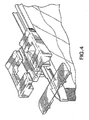
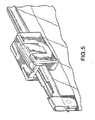
- the slider 23 comprises an inverted generally U-shaped member including a transverse support member or body 29 from which the separator finger 200 extends downward.
- the body 29 is itself U-shaped and includes two integral legs 201 extending downward.
- the finger 200 is positioned between the legs 201.
- the body 29 is adapted to move along the top edges of the tracks 24, 25 with the legs 201 straddling these elements and the finger 200 positioned between the tracks 24, 25.
- the slider 23 also includes a pair of hinged "wings" 202, 203 that can be folded down into their final position.
- the wings 202, 203 are hinged to the main slider body 29 by means of hinge structures 202a, 203a located at the opposite ends of the legs 201.
- the foldable depending wings or side walls 202, 203 extend from an opening end 23a of the slider 23 to a closing end 23b. It is noted that the main slider body 29 and the separator finger 200 are wider at the opening end 23a than at the closing end 23b. Similarly, the side walls 202, 203 and the legs 201 are spaced wider apart at the opening end 23a of the slider 23 to permit separation of the rib and groove profiles 26, 27 by the finger 200 engaging the tracks 24, 25. The wings 202, 203 and legs 201 are spaced sufficiently close together at the closing end 23b of the slider to press the rib and groove profiles 26, 27 into an interlocking relationship as the slider 23 is moved in a closure assembly closing direction. As shown in FIG.
- the side walls 202, 203 at their lower ends are provided with an inwardly extending shoulder structure 204.
- Shoulder structure 204 engages a bottom of the closure assembly 20 to prevent slider 23 from being lifted off the edges of the tracks 24, 25 while the slider 23 straddles the closure assembly 20.
- the slider 23 may be molded from any suitable polymeric material including, but not limited to, polyesters; polystyrenes; nylon; polypropylene; polyethylene; copolymers of polyethylene and polypropylene; polycarbonates; polyacetals; acrylic-butadienestyrene copolymers; monolayer or multilayer polyethylene, such as a low density polyethylene (LDPE), a linear low density polyethylene (LLDPE), high density polyethylenes (HDPE), and/or ethylene vinyl acetate, and/or a co-polymer mixture, multilayer combination, or laminate(s) thereof; or combinations thereof.
- LDPE low density polyethylene
- LLDPE linear low density polyethylene
- HDPE high density polyethylenes
- co-polymer mixture multilayer combination, or laminate(s) thereof; or combinations thereof.
- the opposing ends of the closure assembly 20 can include end stop structures 205 as shown in FIG. 2 and U.S. Patent Number 7,267,856 to Patel et al. .
- a portion of the end stop structures protrudes from the closure assembly 20 a distance adequate to engage the slider 23 and prevent the slider 23 from going past the respective ends of the closure assembly 20 and coming off the ends of the bag 10.
- a portion of the end stops may protrude an adequate distance in the transverse direction to engage the slider 23 and prevent movement of the slider 23 past the respective ends of the closure assembly 20.
- transverse means any direction which is normal to the axis of the track.
- a portion of the end stops may protrude an adequate distance in a generally horizontal or generally vertical direction to engage the slider 23 and prevent movement of the slider 23 past the respective ends of the closure assembly 20. Additionally or alternatively, a portion of the end stops may protrude an adequate distance upwardly and/or outwardly from a remainder of the closure assembly 20 to engage the slider 23 and prevent movement of the slider 23 past the respective ends of the closure assembly 20. Additional details concerning the formation of the end stops may be obtained from U.S. Pat. No. 5,131,121 to Herrington . In some embodiments, the thicknesses of the end stops at their widest point may vary from generally about 0.005 inches to about 0.2770 inches.
- the reclosable fastener comprises a pair of flexible plastic strips having separable fastener means extending along the length thereof comprising reclosable interlocking male and female profile elements on the respective strips.
- the strips include profiled tracks extending along the length thereof parallel to the male and female elements.
- the slider is provided with a separator finger and interlocking complementary structure formed from plastic for moving along the fastener in straddling relation.
- the complementary structure comprises a transverse support member having the separator finger depending therefrom. The support member is positioned on the top edges of the tracks with the separator finger inserted therebetween.
- a pair of side walls are positioned on the opposite sides of the support member for receiving the pair of strips therebetween, the separator finger and the side walls extend from an opening end of the slider to a closing end.
- the separator finger is wider at the opening end of the slider than at the closing end of the slider and the side walls are spaced wider apart at the opening end to permit separation of the male and female elements by the wider end of the separator finger extending between the side walls at the opening end.
- the side walls are spaced sufficiently close together at the closing end to press the male and female elements into interlocking relationship as the slider is moved in a fastener closing direction.
- means for restraining the slider in closed position and maintaining the male and female elements in interlocking relation when the slider reaches the closed end of its travel along its tracks comprising a protrusion on the wider end of the separator finger adjacent the opening end of the slider and notch structure at the adjacent end of the tracks.
- the notch structure has an end located on the tracks to permit the wider end of the separator finger to move beyond the end from between the tracks and into the notch structure.
- the protrusion is engageable with the end of the notch structure when the slider is at the closed end of its travel on the tracks thereby restraining the wider end of the separator finger from moving out of the notch structure and between the tracks and inadvertently opening the male and female elements of the fastener, as shown and described in U.S. Pat. No. 5,067,208 to Herrington, Jr.
- the closure assembly can include fins 280a, 280b which can be configured with sealing ribs 287 to facilitate permanent lock-up seals between the fins 280 and the bag panels 12, 14 at locations 300 and 310.
- a bottom portion of the first fin 280a can extend below the second fin 280b and can be formed with co-ex material and can form a peelable seal 290 between the bottom portion of the first fin 280a and the second bag panel 14 at location 320.
- this configuration is particularly suited for top-fill packages, wherein upon loading of the contents through the mouth 13 of the package, the film panel 12 can be joined to the fin 280a with a permanent lock-up seal.
- FIG. 12 depicts a similar arrangment wherein the fin members 380a, 380b are attached to short film webs 488a, 488b with permanent lock-up seals 400, 410.
- the first fin member 380a extends downward a greater distance than the second fin member 380b, and is attached to the second short film web 488b at location 420 with a peelable seal.
- the use of such short film webs 488a, 488b allows greater flexibility in the manner in which the closure assembly is attached to the bag since the short film webs 488a, 488b can be attached to either the interior surface or exterior surface of the bag panels 12, 14. While FIGS. 9-12 illustrate first fin 280a extending below second fin 280b, it is to be understood that this arrangement could be reversed so that the second fin 280b extended below first fin 280a and attached to panel 12.
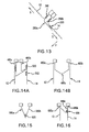
- the gussets expand such that the panels are moved apart which in turn places shearing load "s” on the peelable seal 320, as shown in FIG. 13 .
- the bond of the peelable seal has sufficient strength to resist shearing forces "s” induced by the contents, but is weak in the peal direction "p" which allows a consumer to easily rupture the peelable seal to gain access the contents of the package.
- the bond formed between the closure fin and the bag panel at location 340 is a permanent, "lock-up" type which is capable of withstanding elevated loads regardless of the orientation of the loads.
- the seals disclosed herein i.e., either permanent or peelable, can be formed by a variety of techniques including adhesives, heat-seal, ultrasonic welding, etc. If ultrasonic welding is employed, it is advantageous to use a rotary ultrasonic wheel to form the seals since such an apparatus reduces the drag and heating of the closure assembly, thereby minimizing the formation of wrinkles and other undesirable deformations.
- the strength of the seals disclosed herein, i.e., either permanent or peelable can be varied by altering the amount or type of adhesives, or the duration of the seal time in the case of heat-seal or ultrasonic welding.
- the fin members 480a, 480b are configured as an integral fin having a folded portion which is attached to the panel 14 at two locations 520, 522 with peelable seals, as shown in FIGS. 14A-B .
- the folded portion of the fin includes a line of weakness 480c which can serve as a tamper evident feature.
- the line of weakness is protected from any fill loads or burst pressure by the geometry of the fold which does not have any weakened areas. Consequently, the line of weakness in the fin 480 is ruptured by the consumer to gain access to the contents, and not due to elevated fill loads or drop tests.
- the fins 580a, 580b can be attached to each other with a peelable seal 620 which has sufficient strength to withstand elevated internal forces, yet allows a consumer to access the contents of the package.
- FIG. 16 illustrates a closure assembly with fin members 680a, 680b which are attached to panels 12, 14 and wherein the fin member 680b includes a score or area of weakness 680c.
- This area of weakness 680c allows a user to pierce through the fin member and rupture the peelable seal 620 and access the contents of the package. The closer the peelable seal 620 is located to the mouth of the package, the more the panels will be able to expand and thus dissipate internal forces.
- the peelable seal portions are formed devoid of co-ex material, and thus form a weaker union than the permanent lock-up seals. Consequently, areas of the bag which include a peelable seal material are more susceptible to rupture.
- the fins 280 can be received between opposing bag panels 12, 14 and extend laterally across the entire width of the bag so as to span from one edge 18a to a second edge 18b. Therefore, the presence of the peelable seal material at the edges 18a, b can interrupt or weaken the union of bag panels 12, 14 along the edges 18a, b and thus be detrimental to the bags performance.
- the peelable seal material can include a cut-out or notch portion 15 adjacent to one, or both, edges 18a, 18b of the bag.
- the notches 15 are configured to extend a lateral distance towards the center of the bag and a vertical distance towards the bottom of the bag. While the exemplary embodiment illustrated in Fig. 17 depicts linear notches 15 formed in the fins 280, it is to be understood that the notches can be formed in a variety of shapes and sizes, as so desired.
- the notch can be configured to extend along the entire height of the peelable seal material such that no portion of the peelable seal material is located at the side edges of the film panels 12, 14.
- Providing a notch in the peelable seal material proximate an edge 18a, 18b of the bag allows for a stronger seal along the sides of panels 12, 14 and further enhance the bags resistance to burst pressure. Additionally, in embodiments in which the fins 280 and/or seal member 35 are formed from a different material than the bag panels 12, 14, the notch 15 allows for sealing of only homogeneous materials at the edge (i.e., only the bag panels 12, 14), thereby reducing the chance of pin holes being formed at the sides resulting in a faulty seal.
- the notch 15 can be provided, for example in the fins 280, by removing material from a portion of the fins 28 that includes the peelable seal material.
- the fins 280 can then be inserted between the panels 12, 14 and positioned such that the notched region 15 is registered with the edges 18a, b.
- the bag panels 12, 14 can then be sealed along the edges 18a, b and bottom 16 via any of the sealing techniques described above. Therefore, the peelable seal can be configured to extend a distance between the edges 18a, b of the bag which is less than the width of the bag.
- the profile of the sealed bag edges 18a, b remains uniform along the entire height of the bag, i.e., from the bottom to the mouth of the bag.
- areas of weakness such as perforations can be formed at select locations along the closure assembly thereby allowing the majority of the track fin to remain intact and capable of withstanding the forces generated from filling or dropping the package.
- Areas of weakness in the side gusset are particularly beneficial since the gusset allows for forces to be dissipated by the expansion of the panels and thus protects the area of weakness.
- Indicia such as printed directions, or color codes, can be provided along the closure assembly to aid a consumer in locating the areas of weakness to facilitate opening of the package.
- ribs can be provided on the closure assembly in order to ensure that the area of weakness is provided with a predictable and controlled rupture, especially for packages requiring over 13lbs. force to open.
- the rib design channels the opening of the area of weakness 601 between adjacent ribs 600, which will orient the tear in the machine direction.
- the ribs 600 are positioned between sealing ribs 602. Additionally, resins can be used to aid in the orientation of tearing or opening of the area of weakness.
Landscapes
- Engineering & Computer Science (AREA)
- Mechanical Engineering (AREA)
- Bag Frames (AREA)
- Packages (AREA)
- Slide Fasteners (AREA)
- Cartons (AREA)
Claims (3)
- Eine wiederverschließbare Verpackung (10), umfassend:eine erste Platte (12) und eine zweite Platte (14), die entlang eines ersten Seitenabschnitts und eines zweiten Seitenabschnitts (18a, 18b) verbunden sind;einen Boden (16), der sich zwischen dem ersten und dem zweiten Seitenabschnitt der ersten und zweiten Platte erstreckt, wobei die erste und zweite Platte miteinander verbunden sind;eine Öffnung (13), die gegenüber dem Boden angeordnet ist und sich zwischen dem ersten und dem zweiten Seitenabschnitt der ersten und der zweiten Platte erstreckt; undeine Verschlussanordnung (20), die sich entlang der Öffnung erstreckt, wobei die Verschlussanordnung ein erstes Rippenelement (480a), das an der ersten Platte befestigt ist, und ein zweites Rippenelement (480b), das an der zweiten Platte befestigt ist, beinhaltet; worindas erste Rippenelement (480a) und das zweite Rippenelement (480b) gemeinsam als fest eingebautes Rippenelement ausgebildet sind, dadurch gekennzeichnet, dass das fest eingebaute Rippenelement mit zwei abziehbaren Versiegelungen (520, 522) an der zweiten Platte befestigt ist.
- Die wiederverschließbare Verpackung (10) von Anspruch 1, worin ein oberer Abschnitt der fest eingebauten Rippe mit einer Sperrversiegelung an der ersten Platte (12) befestigt ist und ein unterer Abschnitt der fest eingebauten Rippe mit den beiden abziehbaren Versiegelungen (520, 522) an der zweiten Platte (14) befestigt ist.
- Die wiederverschließbare Verpackung (10) von Anspruch 1, worin der erste und zweite Seitenabschnitt (18a, 18b) eine Verpackungsbreite definieren und die beiden abziehbaren Versiegelungen (520, 522) sich zwischen dem ersten und dem zweiten Seitenabschnitt erstrecken, wobei der Abstand dazwischen kürzer als die Verpackungsbreite ist.
Priority Applications (10)
| Application Number | Priority Date | Filing Date | Title |
|---|---|---|---|
| PL12154536T PL2452888T3 (pl) | 2008-04-23 | 2009-04-23 | Zamknięcie opakowania odporne na działanie sił wewnętrznych |
| EP15152633.2A EP2902335B1 (de) | 2008-04-23 | 2009-04-23 | Gegen innere Kräfte beständiger Verpackungsverschluss |
| EP13177324.4A EP2669211B1 (de) | 2008-04-23 | 2009-04-23 | Gegen innere Kräfte beständiger Verpackungsverschluss |
| DK13177324.4T DK2669211T3 (en) | 2008-04-23 | 2009-04-23 | Gasket closure that can withstand internal forces |
| EP18185284.9A EP3434613B1 (de) | 2008-04-23 | 2009-04-23 | Gegen innere kräfte beständiger verpackungsverschluss |
| EP17160619.7A EP3196141B1 (de) | 2008-04-23 | 2009-04-23 | Gegen innere kräfte beständiger verpackungsverschluss |
| PL15152633T PL2902335T3 (pl) | 2008-04-23 | 2009-04-23 | Zamknięcie opakowania do wytrzymywania wewnętrznych sił |
| PL17160619T PL3196141T3 (pl) | 2008-04-23 | 2009-04-23 | Zamknięcie opakowania do wytrzymywania sił wewnętrznych |
| PL18185284T PL3434613T3 (pl) | 2008-04-23 | 2009-04-23 | Zamknięcie opakowania do wytrzymywania sił wewnętrznych |
| PL13177324T PL2669211T3 (pl) | 2008-04-23 | 2009-04-23 | Zamknięcie opakowania odporne na działanie sił wewnętrznych |
Applications Claiming Priority (2)
| Application Number | Priority Date | Filing Date | Title |
|---|---|---|---|
| US4732708P | 2008-04-23 | 2008-04-23 | |
| EP09733813A EP2265506B1 (de) | 2008-04-23 | 2009-04-23 | Gegen innere kräfte beständiger verpackungsverschluss |
Related Parent Applications (3)
| Application Number | Title | Priority Date | Filing Date |
|---|---|---|---|
| EP09733813A Division-Into EP2265506B1 (de) | 2008-04-23 | 2009-04-23 | Gegen innere kräfte beständiger verpackungsverschluss |
| EP09733813A Division EP2265506B1 (de) | 2008-04-23 | 2009-04-23 | Gegen innere kräfte beständiger verpackungsverschluss |
| EP09733813.1 Division | 2009-04-23 |
Related Child Applications (5)
| Application Number | Title | Priority Date | Filing Date |
|---|---|---|---|
| EP15152633.2A Division EP2902335B1 (de) | 2008-04-23 | 2009-04-23 | Gegen innere Kräfte beständiger Verpackungsverschluss |
| EP17160619.7A Division EP3196141B1 (de) | 2008-04-23 | 2009-04-23 | Gegen innere kräfte beständiger verpackungsverschluss |
| EP13177324.4A Division EP2669211B1 (de) | 2008-04-23 | 2009-04-23 | Gegen innere Kräfte beständiger Verpackungsverschluss |
| EP13177324.4A Division-Into EP2669211B1 (de) | 2008-04-23 | 2009-04-23 | Gegen innere Kräfte beständiger Verpackungsverschluss |
| EP18185284.9A Division EP3434613B1 (de) | 2008-04-23 | 2009-04-23 | Gegen innere kräfte beständiger verpackungsverschluss |
Publications (2)
| Publication Number | Publication Date |
|---|---|
| EP2452888A1 EP2452888A1 (de) | 2012-05-16 |
| EP2452888B1 true EP2452888B1 (de) | 2014-04-16 |
Family
ID=40750843
Family Applications (6)
| Application Number | Title | Priority Date | Filing Date |
|---|---|---|---|
| EP17160619.7A Active EP3196141B1 (de) | 2008-04-23 | 2009-04-23 | Gegen innere kräfte beständiger verpackungsverschluss |
| EP09733813A Active EP2265506B1 (de) | 2008-04-23 | 2009-04-23 | Gegen innere kräfte beständiger verpackungsverschluss |
| EP12154536.2A Active EP2452888B1 (de) | 2008-04-23 | 2009-04-23 | Gegen innere Kräfte beständiger Verpackungsverschluss |
| EP15152633.2A Active EP2902335B1 (de) | 2008-04-23 | 2009-04-23 | Gegen innere Kräfte beständiger Verpackungsverschluss |
| EP13177324.4A Active EP2669211B1 (de) | 2008-04-23 | 2009-04-23 | Gegen innere Kräfte beständiger Verpackungsverschluss |
| EP18185284.9A Active EP3434613B1 (de) | 2008-04-23 | 2009-04-23 | Gegen innere kräfte beständiger verpackungsverschluss |
Family Applications Before (2)
| Application Number | Title | Priority Date | Filing Date |
|---|---|---|---|
| EP17160619.7A Active EP3196141B1 (de) | 2008-04-23 | 2009-04-23 | Gegen innere kräfte beständiger verpackungsverschluss |
| EP09733813A Active EP2265506B1 (de) | 2008-04-23 | 2009-04-23 | Gegen innere kräfte beständiger verpackungsverschluss |
Family Applications After (3)
| Application Number | Title | Priority Date | Filing Date |
|---|---|---|---|
| EP15152633.2A Active EP2902335B1 (de) | 2008-04-23 | 2009-04-23 | Gegen innere Kräfte beständiger Verpackungsverschluss |
| EP13177324.4A Active EP2669211B1 (de) | 2008-04-23 | 2009-04-23 | Gegen innere Kräfte beständiger Verpackungsverschluss |
| EP18185284.9A Active EP3434613B1 (de) | 2008-04-23 | 2009-04-23 | Gegen innere kräfte beständiger verpackungsverschluss |
Country Status (12)
| Country | Link |
|---|---|
| US (2) | US11220374B2 (de) |
| EP (6) | EP3196141B1 (de) |
| JP (2) | JP5571066B2 (de) |
| AU (1) | AU2009240577B2 (de) |
| CA (1) | CA2721405C (de) |
| DK (4) | DK2669211T3 (de) |
| ES (6) | ES2800451T3 (de) |
| HU (2) | HUE034486T2 (de) |
| PL (6) | PL2669211T3 (de) |
| PT (6) | PT3434613T (de) |
| TR (1) | TR201816535T4 (de) |
| WO (1) | WO2009132199A1 (de) |
Families Citing this family (8)
| Publication number | Priority date | Publication date | Assignee | Title |
|---|---|---|---|---|
| US8540427B2 (en) * | 2008-03-07 | 2013-09-24 | Mark Steele | Gusseted package with impact barrier |
| FR2962112A1 (fr) * | 2010-07-05 | 2012-01-06 | Francis Gathie | Emballage d'expedition reutilisable |
| US20120269469A1 (en) * | 2010-10-04 | 2012-10-25 | Exopack Llc | Reclosable full open mouth bag with a hook and hook closure and associated methods |
| US9487333B2 (en) | 2010-10-04 | 2016-11-08 | Coveris Flexibles Us Llc | Packaging for steaming and related methods |
| US8690430B2 (en) | 2012-06-20 | 2014-04-08 | S.C. Johnson & Son, Inc. | Storage bag having a slider with ridges that presses together and separates interlocking profiles of fastener strips |
| JP6878879B2 (ja) * | 2016-12-26 | 2021-06-02 | 大日本印刷株式会社 | 包装袋 |
| CN108577109B (zh) * | 2018-07-17 | 2024-05-07 | 广东爱子优旺新材料有限公司 | 防止儿童打开的拉链袋 |
| US20250326563A1 (en) * | 2024-04-18 | 2025-10-23 | Reynolds Consumer Products LLC | Package of reclosable bags with staggered sliders |
Family Cites Families (126)
| Publication number | Priority date | Publication date | Assignee | Title |
|---|---|---|---|---|
| GB994307A (en) | 1961-11-27 | 1965-06-02 | Seisan Nipponsha Kk | Material for forming plastics bags and bags made therefrom |
| US3256981A (en) | 1962-11-01 | 1966-06-21 | Leonard D Kurtz | Strippable package for sutures |
| US3217871A (en) | 1963-05-06 | 1965-11-16 | Acme Backing Corp | Peelable seal package |
| US3329331A (en) | 1964-01-09 | 1967-07-04 | Morgan Adhesives Co | Resealable containers and flexible laminate therefor |
| US3339606A (en) | 1966-06-14 | 1967-09-05 | Kugler Emanuel | Slide closure |
| US3511436A (en) | 1966-09-12 | 1970-05-12 | Us Plywood Champ Papers Inc | Easy opening heat sealed package |
| US3368740A (en) | 1967-01-17 | 1968-02-13 | Tower Packaging Company | Sheet material with film tear line |
| US3535409A (en) | 1967-01-17 | 1970-10-20 | Tower Products | Method of making sheet material with film tear line |
| US3655503A (en) | 1969-01-13 | 1972-04-11 | Crown Zellerbach Corp | Package of composite film with peelable, heatsealable surfaces |
| US3613874A (en) | 1969-08-21 | 1971-10-19 | Reclosable Package Corp | Reclosable package |
| US3625270A (en) | 1970-04-17 | 1971-12-07 | Milorad Skendzic | Pilferproof package |
| US3711011A (en) | 1970-05-04 | 1973-01-16 | Action Packaging Corp | Resealable packaging device |
| US3791916A (en) | 1971-12-06 | 1974-02-12 | Grace W R & Co | Sealing polystyrene |
| US3827625A (en) | 1972-06-21 | 1974-08-06 | Reclosable Package Corp | Reclosable package and controlled release paper for use therein |
| US4252846A (en) | 1975-09-22 | 1981-02-24 | The Dow Chemical Company | Packages embodying a controlled peel seal and method of preparing same |
| US3967729A (en) | 1975-09-29 | 1976-07-06 | Johnson & Johnson | Fully sealed package for sterile contents |
| US4097236A (en) | 1977-01-24 | 1978-06-27 | Faser Industries | Method of detecting heat seal breaks and package thereof |
| US4295919A (en) | 1978-12-15 | 1981-10-20 | The Dow Chemical Co. | Forming an integral closure for a thermoplastic container |
| GB2054451B (en) | 1979-08-06 | 1983-12-14 | Roeder Ind Holdings | Making tubular plastics intermediate product and forming reclosable bags therefrom |
| US4279677A (en) | 1979-11-16 | 1981-07-21 | Seissan Nippon-Sha K. K. | Method of means for joining plastic fastener strip to film |
| US4638913A (en) | 1981-08-21 | 1987-01-27 | W. R. Grace & Co., Cryovac Div. | Multiply package having delaminating easy open seal |
| SE428290B (sv) | 1981-08-28 | 1983-06-20 | Rigello Pak Ab | Oppningsanordning for forpackningsbehallare med trycksatt fyllgods |
| US5033868A (en) | 1982-06-14 | 1991-07-23 | Paramount Packaging Corporation | Flexible plastic bag with perforated handle |
| US4738998A (en) | 1982-08-12 | 1988-04-19 | Owens-Corning Fiberglas Corporation | Hot-melt adhesive |
| US4576285A (en) | 1983-05-20 | 1986-03-18 | Fres-Co System Usa, Inc. | Sealed flexible container with non-destructive peelable opening and apparatus and method for forming same |
| US4589145A (en) | 1983-10-31 | 1986-05-13 | Signode Corporation | Packaging material and package |
| US4663915A (en) | 1983-10-31 | 1987-05-12 | Signode Corporation | Method of packaging and apparatus |
| US4705174A (en) | 1984-02-29 | 1987-11-10 | Fres-Co System Usa, Inc. | Sealed flexible container with non-destructive peelable opening |
| US4630311A (en) | 1984-11-29 | 1986-12-16 | Minigrip, Inc. | Zipper-lock bag chain with tearable strip interconnection means |
| US4875587A (en) | 1985-02-21 | 1989-10-24 | W. R. Grace & Co.-Conn. | Easy open shrinkable laminate |
| JPH0532288Y2 (de) | 1986-04-07 | 1993-08-18 | ||
| US4925316A (en) | 1986-08-11 | 1990-05-15 | Minigrip, Inc. | Reclosable bag having an outer reclosable zipper type closure and inner non-reclosable closure |
| US4784885A (en) | 1986-08-29 | 1988-11-15 | R. J. Reynolds Tobacco Company | Peelable film laminate |
| US4736451A (en) | 1986-12-22 | 1988-04-05 | Minigrip, Inc. | Extruded zipper having combination stabilizing and differential opening means |
| US4855168A (en) | 1987-04-07 | 1989-08-08 | Yoshino Kogyosho Co., Ltd. | Synthetic resin sheet having notching strip and container |
| DE3873265T2 (de) | 1987-05-20 | 1993-03-11 | Toyo Seikan Kaisha Ltd | Leicht zu oeffnender behaelter mit abgedichtetem verschluss. |
| US5143961A (en) | 1987-06-29 | 1992-09-01 | H. B. Fuller Licensing & Financing Inc. | Hot melt adhesive comprising water soluble polyalkyloxazoline and water insoluble polymer |
| US5024888A (en) | 1987-08-31 | 1991-06-18 | Shell Oil Company | Modified polybutylene-base hot melt compositions |
| US4977206A (en) | 1987-08-31 | 1990-12-11 | Shell Oil Company | Modified polybutylene-based hot melt compositions |
| DE3800432A1 (de) | 1988-01-09 | 1989-07-20 | Hauni Werke Koerber & Co Kg | Vorrichtung zum einhuellen von packungen mit huellmaterial |
| US4846585A (en) | 1988-01-29 | 1989-07-11 | Minigrip, Inc. | Easy open bag structure |
| US4944409A (en) | 1988-02-10 | 1990-07-31 | Curwood, Inc. | Easy open package |
| US4889731A (en) | 1988-02-12 | 1989-12-26 | W. R. Grace & Co.-Conn. | Package having peelable film |
| US4937040A (en) | 1988-03-07 | 1990-06-26 | Minnesota Mining And Manufacturing Company | Security deposit bag |
| US4834552A (en) | 1988-03-23 | 1989-05-30 | Makowka Kenneth R | Tamper-evident seal for envelope and method of making same |
| US4998666A (en) | 1988-05-13 | 1991-03-12 | Frederick R. Ewan | Tamper indicating containers and seals |
| US4949527A (en) * | 1988-06-29 | 1990-08-21 | Zip-Pak Incorporated | Method of forming a reclosable tray |
| DK576888D0 (da) | 1988-10-17 | 1988-10-17 | Schur Int As Brdr | Fremgangsmaade ved fremstilling af poseemballager med oprivelig svejselukning, saadanne emballager med genlukningsprofildele, samt hjaelpemateriale til brug ved denne fremstilling |
| US5077001A (en) | 1988-11-21 | 1991-12-31 | Makowka Kenneth R | Tamper-evident sealing system for envelope having special characteristics and method of making same |
| US4969967A (en) | 1989-01-18 | 1990-11-13 | Schurpack, Inc. | Method of manufacturing packing and strip material therefor |
| US4966470A (en) | 1989-02-24 | 1990-10-30 | Oscar Mayer Foods Corporation | Tamper-evident, reclosable, flexible packages |
| US5224779A (en) | 1989-02-24 | 1993-07-06 | Oscar Mayer Foods Corporation | Tamper-evident, reclosable flexible packages |
| US4923309A (en) | 1989-02-27 | 1990-05-08 | Illinois Tool Works | Tamper-evident package |
| US5063069A (en) | 1989-03-23 | 1991-11-05 | Zip-Pak Incorporated | Zippered closure for thermoformed package |
| US5067822A (en) | 1989-04-24 | 1991-11-26 | Reynolds Consumer Products, Inc. | Method of forming recloseable packages, profiles used therein, and packages produced thereby |
| US5017021A (en) | 1989-05-19 | 1991-05-21 | Reynolds Consumer Products, Inc. | Reclosable profile having improved closure members |
| US5238306A (en) | 1989-05-19 | 1993-08-24 | Reynolds Consumer Products, Inc. | Method of producing a sealing system for a reclosable webbed-wall package, and system made |
| CA2019761C (en) | 1989-06-30 | 2000-04-25 | Gerald O. Hustad | Tamper-evident, flexible, reclosable packages |
| US4909017B1 (en) * | 1989-07-28 | 1999-02-09 | Minigrip Inc | Reclosable bag material method and apparatus |
| US5582887A (en) | 1989-08-17 | 1996-12-10 | The Kendall Company | Tamper-evident tape having discontinuous barrier layer |
| US5103979A (en) | 1989-10-11 | 1992-04-14 | Oscar Mayer Foods Corp. | Package having peel seal tamper-evidence message |
| US5022530A (en) | 1989-10-13 | 1991-06-11 | The Dow Chemical Company | Modified zipper elements for easy open containers |
| US5007143A (en) | 1990-03-07 | 1991-04-16 | Mobil Oil Corp. | Rolling action zipper profile and slipper therefor |
| US5064664A (en) | 1990-04-04 | 1991-11-12 | Oscar Mayer Foods Corporation | Package having engraved lettering peel seal tamper-evidence message |
| US5082702A (en) | 1990-08-20 | 1992-01-21 | Minnesota Mining And Manufacturing Company | Tamper-indicating tape |
| US5104704A (en) | 1990-10-09 | 1992-04-14 | Temple University | Gel-interleaved tamper-evident wrap |
| US5100246A (en) | 1990-10-09 | 1992-03-31 | Illinois Tool Works Inc. | Pull bead and guide rails for easy open flexible containers |
| US5215380A (en) | 1990-10-19 | 1993-06-01 | Reynolds Consumer Products, Inc. | Reclosable package with tear strip |
| US5067208A (en) | 1991-03-22 | 1991-11-26 | Mobil Oil Corporation | Plastic reclosable fastener with self-locking slider |
| US5131121A (en) | 1991-03-22 | 1992-07-21 | Mobil Oil Corporation | Protruding end stops for plastic reclosable fastener |
| TW243431B (en) | 1991-05-31 | 1995-03-21 | Gen Foods Inc | Pouch having easy opening and reclosing characteristics and method and apparatus for production thereof |
| EP0541093B1 (de) | 1991-11-08 | 1997-02-26 | Toyo Aluminium Kabushiki Kaisha | Durch Heisssiegeln siegelbare Verpackung |
| US5360845A (en) | 1992-12-23 | 1994-11-01 | National Starch And Chemical Investment Holding Corporation | Starch ester based hot melt adhesive |
| US5358334A (en) | 1993-02-11 | 1994-10-25 | Reynolds Consumer Products Inc. | Reclosable profile strip with joining web |
| US5346301A (en) | 1993-04-02 | 1994-09-13 | Paul W. Scarberry | Reclosable bag with offset end seal |
| US5425825A (en) | 1993-04-22 | 1995-06-20 | Rasko; George | Reclosable zipper with tamper evident feature |
| JPH07112746A (ja) | 1993-10-19 | 1995-05-02 | Idemitsu Petrochem Co Ltd | 易開封性密封袋 |
| US5407278A (en) | 1993-12-10 | 1995-04-18 | Fres-Co System Usa, Inc. | Dual compartment easily openable flexible package |
| US5725312A (en) | 1994-04-11 | 1998-03-10 | Reynolds Consumer Products, Inc. | Closure arrangement having a peelable seal |
| US5893645A (en) | 1994-04-11 | 1999-04-13 | Reynolds Consumer Products, Inc. | Closure arrangement having peelable seal |
| US5486051A (en) | 1994-04-11 | 1996-01-23 | Reynolds Consumer Products Inc. | Closure arrangement having a breakaway seal |
| US5513915A (en) | 1994-04-11 | 1996-05-07 | Reynolds Consumer Products Inc. | Closure arrangement having a breakaway seal |
| US5647671A (en) * | 1994-04-11 | 1997-07-15 | Reynolds Consumer Products, Inc. | Closure arrangement having a peelable seal |
| US5470156A (en) | 1994-04-11 | 1995-11-28 | Reynolds Consumer Products, Inc. | Closure arrangement having a peelable seal |
| US5604000A (en) | 1995-01-18 | 1997-02-18 | Reynolds Consumer Products Inc. | Heat-sealable peelable composition |
| US5492411A (en) | 1995-01-18 | 1996-02-20 | Reynolds Consumer Products Inc. | Tamper evident peelable seal |
| US5474382A (en) | 1995-05-01 | 1995-12-12 | Reynolds Consumer Products Inc. | Closure arrangement having a peelable seal |
| US5769772A (en) * | 1996-08-13 | 1998-06-23 | Tenneco Packaging Inc. | Packages made with both high-frequency/radio-frequency seals and conventional heat/pressure seals using combinations of polar and non-polar polymers |
| US5896627A (en) | 1997-09-26 | 1999-04-27 | Tenneco Packaging Inc. | High-strength slider for a reclosable bag |
| US6216423B1 (en) * | 1997-11-07 | 2001-04-17 | Huntsman Kcl Corporation | Method and apparatus for placing a product in a flexible recloseable container |
| US5911508A (en) * | 1997-11-10 | 1999-06-15 | Dobreski; David V. | Vented reclosable bag |
| US6131248A (en) | 1998-03-13 | 2000-10-17 | Reynolds Consumer Products, Inc. | Peelable seal on closure mechanism and method therefor |
| US6154934A (en) | 1999-02-10 | 2000-12-05 | Illinois Tool Works, Inc. | Reclosable zipper with fusible rib layer |
| US6360513B1 (en) * | 1999-05-11 | 2002-03-26 | Sargento Foods Inc. | Resealable bag for filling with food product(s) and method |
| US6071011A (en) | 1999-08-12 | 2000-06-06 | Tenneco Packaging, Inc. | Fill-through-the-top package |
| US6290391B1 (en) * | 2000-01-18 | 2001-09-18 | Reynolds Consumer Products, Inc. | Reclosable package having slider device and tamper-evident structure |
| US20010053253A1 (en) * | 2000-03-24 | 2001-12-20 | Reynolds Consumer Products, Inc. | Reclosable package having zipper closure, slider device and dual tamper-evident structures; and methods |
| US6183134B1 (en) | 2000-05-04 | 2001-02-06 | Illinois Tool Works, Inc. | High internal force resistant peel sealable zipper |
| US6378177B1 (en) | 2000-06-28 | 2002-04-30 | Pactiv Corporation | Top-filled tamper-evident package |
| US6290393B1 (en) | 2000-07-21 | 2001-09-18 | Reynolds Consumer Products, Inc. | Slider reclosable packages with dual peel seals |
| US6354738B1 (en) * | 2000-10-24 | 2002-03-12 | Illinois Tool Works Inc. | Tamper evident reclosable plastic bag |
| US20020094137A1 (en) * | 2001-01-16 | 2002-07-18 | Schneider John H. | Tamper evident resealable packaging |
| US6505383B2 (en) * | 2001-01-30 | 2003-01-14 | Illinois Tool Works Inc. | Reclosable zipper strip with coated webs |
| US7413535B2 (en) * | 2001-07-27 | 2008-08-19 | Illinois Tool Works Inc. | Method for manufacturing tamper evident reclosable plastic bags |
| US6713152B2 (en) * | 2001-09-07 | 2004-03-30 | Pactiv Corporation | Fins and profiles for plastic bags |
| US6901637B2 (en) | 2001-10-03 | 2005-06-07 | Illinois Tool Works Inc. | Zipper with pre-activated peel-seal |
| US20060291756A1 (en) * | 2002-02-27 | 2006-12-28 | Thomas Toby R | Web materials with active agent for use in forming reclosable packages |
| US7040808B2 (en) * | 2002-03-20 | 2006-05-09 | Pactiv Corporation | Reclosable bags with tamper evident features and methods of making the same |
| US6830377B2 (en) * | 2002-05-30 | 2004-12-14 | Illinois Tool Works Inc. | Reclosable packaging with gas barrier incorporated in zipper |
| CA2490073A1 (en) | 2002-06-17 | 2003-12-24 | Pliant Corporation | Peel seal tamper evident slider bag |
| US7267856B2 (en) | 2002-10-07 | 2007-09-11 | Pactiv Corporation | Ultrasonic end stops on zipper closure bags and methods for making same |
| US20040131283A1 (en) * | 2002-12-03 | 2004-07-08 | Sprague Paul A. | Autoclavable reclosable package |
| US7306370B2 (en) * | 2003-07-31 | 2007-12-11 | Kraft Foods Holdings, Inc. | Shrouded flexible packages |
| US20050063617A1 (en) * | 2003-09-15 | 2005-03-24 | Tilman Paul A. | Reclosable bag having tamper-evident membrane |
| US7263748B2 (en) | 2003-12-02 | 2007-09-04 | Pactiv Corporation | Slider for reclosable fastener |
| US6845598B1 (en) * | 2003-12-19 | 2005-01-25 | Reynolds Consumer Products, Inc. | Top filled reclosable package and method for forming and filling the same |
| EP1740483B1 (de) * | 2004-02-10 | 2009-10-07 | Pactiv Corporation | Wiederverschliessbare verpackungen mit wirkstoffen |
| US7351188B2 (en) * | 2004-08-05 | 2008-04-01 | Illinois Tool Works Inc. | Hooded reclosable packages and related methods of manufacture |
| JP2006111277A (ja) * | 2004-10-12 | 2006-04-27 | Idemitsu Unitech Co Ltd | チャックテープ付き包装袋 |
| WO2006090693A1 (ja) * | 2005-02-22 | 2006-08-31 | Idemitsu Unitech Co., Ltd. | 咬合具付きテープ |
| US20080019619A9 (en) * | 2005-04-12 | 2008-01-24 | Eads Claude A | Tamper evident reclosable seals |
| US20060257533A1 (en) * | 2005-05-12 | 2006-11-16 | Plourde Eric P | Self-venting reclosable packages |
| US9011003B2 (en) * | 2006-02-08 | 2015-04-21 | S.C. Johnson Home Storage, Inc. | Reclosable pouch and zipper for a reclosable pouch |
| JP2007261640A (ja) * | 2006-03-29 | 2007-10-11 | Toyo Seikan Kaisha Ltd | 加熱殺菌可能なファスナー及び包装袋 |
| JP2007331805A (ja) * | 2006-06-16 | 2007-12-27 | Dainippon Printing Co Ltd | チャック及びそれを用いた加熱殺菌可能なチャック付き袋 |
| US8677722B2 (en) | 2006-08-23 | 2014-03-25 | Illinois Tool Works Inc. | Hot melt adhesive systems for zipper assemblies on large bag constructions of various substrates |
-
2009
- 2009-04-23 PT PT181852849T patent/PT3434613T/pt unknown
- 2009-04-23 DK DK13177324.4T patent/DK2669211T3/en active
- 2009-04-23 EP EP17160619.7A patent/EP3196141B1/de active Active
- 2009-04-23 PL PL13177324T patent/PL2669211T3/pl unknown
- 2009-04-23 PL PL09733813T patent/PL2265506T3/pl unknown
- 2009-04-23 CA CA2721405A patent/CA2721405C/en active Active
- 2009-04-23 PT PT131773244T patent/PT2669211E/pt unknown
- 2009-04-23 JP JP2011506452A patent/JP5571066B2/ja active Active
- 2009-04-23 WO PCT/US2009/041552 patent/WO2009132199A1/en not_active Ceased
- 2009-04-23 TR TR2018/16535T patent/TR201816535T4/tr unknown
- 2009-04-23 DK DK18185284.9T patent/DK3434613T3/da active
- 2009-04-23 ES ES18185284T patent/ES2800451T3/es active Active
- 2009-04-23 EP EP09733813A patent/EP2265506B1/de active Active
- 2009-04-23 PL PL18185284T patent/PL3434613T3/pl unknown
- 2009-04-23 DK DK15152633.2T patent/DK2902335T3/en active
- 2009-04-23 PT PT09733813T patent/PT2265506E/pt unknown
- 2009-04-23 ES ES17160619.7T patent/ES2693605T3/es active Active
- 2009-04-23 PT PT151526332T patent/PT2902335T/pt unknown
- 2009-04-23 PL PL17160619T patent/PL3196141T3/pl unknown
- 2009-04-23 EP EP12154536.2A patent/EP2452888B1/de active Active
- 2009-04-23 DK DK17160619.7T patent/DK3196141T3/en active
- 2009-04-23 PL PL15152633T patent/PL2902335T3/pl unknown
- 2009-04-23 ES ES12154536.2T patent/ES2472541T3/es active Active
- 2009-04-23 PT PT17160619T patent/PT3196141T/pt unknown
- 2009-04-23 EP EP15152633.2A patent/EP2902335B1/de active Active
- 2009-04-23 AU AU2009240577A patent/AU2009240577B2/en active Active
- 2009-04-23 EP EP13177324.4A patent/EP2669211B1/de active Active
- 2009-04-23 PT PT121545362T patent/PT2452888E/pt unknown
- 2009-04-23 HU HUE15152633A patent/HUE034486T2/en unknown
- 2009-04-23 EP EP18185284.9A patent/EP3434613B1/de active Active
- 2009-04-23 HU HUE18185284A patent/HUE051955T2/hu unknown
- 2009-04-23 PL PL12154536T patent/PL2452888T3/pl unknown
- 2009-04-23 ES ES09733813T patent/ES2394601T3/es active Active
- 2009-04-23 ES ES15152633.2T patent/ES2641587T3/es active Active
- 2009-04-23 ES ES13177324.4T patent/ES2533324T3/es active Active
-
2010
- 2010-10-22 US US12/910,487 patent/US11220374B2/en active Active
-
2014
- 2014-06-25 JP JP2014130330A patent/JP6101234B2/ja active Active
-
2021
- 2021-11-02 US US17/517,052 patent/US20220055800A1/en not_active Abandoned
Also Published As
Similar Documents
| Publication | Publication Date | Title |
|---|---|---|
| US20220055800A1 (en) | Package closure for withstanding internal forces | |
| EP2485954B1 (de) | Karton mit wiederverschliessbarem deckel | |
| EP1642839B1 (de) | Mehrschichtiger Beutel mit einem Reisverschluss mit Schieber | |
| AU2015202504B2 (en) | Package closure for withstanding internal forces |
Legal Events
| Date | Code | Title | Description |
|---|---|---|---|
| PUAI | Public reference made under article 153(3) epc to a published international application that has entered the european phase |
Free format text: ORIGINAL CODE: 0009012 |
|
| 17P | Request for examination filed |
Effective date: 20120208 |
|
| AC | Divisional application: reference to earlier application |
Ref document number: 2265506 Country of ref document: EP Kind code of ref document: P |
|
| AK | Designated contracting states |
Kind code of ref document: A1 Designated state(s): AT BE BG CH CY CZ DE DK EE ES FI FR GB GR HR HU IE IS IT LI LT LU LV MC MK MT NL NO PL PT RO SE SI SK TR |
|
| 17Q | First examination report despatched |
Effective date: 20130110 |
|
| GRAP | Despatch of communication of intention to grant a patent |
Free format text: ORIGINAL CODE: EPIDOSNIGR1 |
|
| RAP1 | Party data changed (applicant data changed or rights of an application transferred) |
Owner name: REYNOLDS CONSUMER PRODUCTS INC. |
|
| INTG | Intention to grant announced |
Effective date: 20131029 |
|
| RAP1 | Party data changed (applicant data changed or rights of an application transferred) |
Owner name: REYNOLDS PRESTO PRODUCTS INC. |
|
| RIN1 | Information on inventor provided before grant (corrected) |
Inventor name: FLEURY, JANET Inventor name: SOLLER, CRAIG Inventor name: DOWLER, ROGER E Inventor name: CAMERON, DAVID Inventor name: BOHN, MICHAEL |
|
| GRAS | Grant fee paid |
Free format text: ORIGINAL CODE: EPIDOSNIGR3 |
|
| GRAA | (expected) grant |
Free format text: ORIGINAL CODE: 0009210 |
|
| AC | Divisional application: reference to earlier application |
Ref document number: 2265506 Country of ref document: EP Kind code of ref document: P |
|
| AK | Designated contracting states |
Kind code of ref document: B1 Designated state(s): AT BE BG CH CY CZ DE DK EE ES FI FR GB GR HR HU IE IS IT LI LT LU LV MC MK MT NL NO PL PT RO SE SI SK TR |
|
| REG | Reference to a national code |
Ref country code: GB Ref legal event code: FG4D |
|
| REG | Reference to a national code |
Ref country code: CH Ref legal event code: NV Representative=s name: BOVARD AG, CH Ref country code: CH Ref legal event code: EP |
|
| REG | Reference to a national code |
Ref country code: AT Ref legal event code: REF Ref document number: 662367 Country of ref document: AT Kind code of ref document: T Effective date: 20140515 |
|
| REG | Reference to a national code |
Ref country code: IE Ref legal event code: FG4D |
|
| REG | Reference to a national code |
Ref country code: NL Ref legal event code: T3 Ref country code: DE Ref legal event code: R096 Ref document number: 602009023390 Country of ref document: DE Effective date: 20140528 |
|
| REG | Reference to a national code |
Ref country code: PT Ref legal event code: SC4A Free format text: AVAILABILITY OF NATIONAL TRANSLATION Effective date: 20140603 |
|
| REG | Reference to a national code |
Ref country code: ES Ref legal event code: FG2A Ref document number: 2472541 Country of ref document: ES Kind code of ref document: T3 Effective date: 20140701 |
|
| REG | Reference to a national code |
Ref country code: PL Ref legal event code: T3 |
|
| REG | Reference to a national code |
Ref country code: LT Ref legal event code: MG4D |
|
| PG25 | Lapsed in a contracting state [announced via postgrant information from national office to epo] |
Ref country code: LT Free format text: LAPSE BECAUSE OF FAILURE TO SUBMIT A TRANSLATION OF THE DESCRIPTION OR TO PAY THE FEE WITHIN THE PRESCRIBED TIME-LIMIT Effective date: 20140416 Ref country code: CY Free format text: LAPSE BECAUSE OF FAILURE TO SUBMIT A TRANSLATION OF THE DESCRIPTION OR TO PAY THE FEE WITHIN THE PRESCRIBED TIME-LIMIT Effective date: 20140416 Ref country code: IS Free format text: LAPSE BECAUSE OF FAILURE TO SUBMIT A TRANSLATION OF THE DESCRIPTION OR TO PAY THE FEE WITHIN THE PRESCRIBED TIME-LIMIT Effective date: 20140816 Ref country code: GR Free format text: LAPSE BECAUSE OF FAILURE TO SUBMIT A TRANSLATION OF THE DESCRIPTION OR TO PAY THE FEE WITHIN THE PRESCRIBED TIME-LIMIT Effective date: 20140717 Ref country code: NO Free format text: LAPSE BECAUSE OF FAILURE TO SUBMIT A TRANSLATION OF THE DESCRIPTION OR TO PAY THE FEE WITHIN THE PRESCRIBED TIME-LIMIT Effective date: 20140716 Ref country code: BG Free format text: LAPSE BECAUSE OF FAILURE TO SUBMIT A TRANSLATION OF THE DESCRIPTION OR TO PAY THE FEE WITHIN THE PRESCRIBED TIME-LIMIT Effective date: 20140716 Ref country code: FI Free format text: LAPSE BECAUSE OF FAILURE TO SUBMIT A TRANSLATION OF THE DESCRIPTION OR TO PAY THE FEE WITHIN THE PRESCRIBED TIME-LIMIT Effective date: 20140416 |
|
| PG25 | Lapsed in a contracting state [announced via postgrant information from national office to epo] |
Ref country code: HR Free format text: LAPSE BECAUSE OF FAILURE TO SUBMIT A TRANSLATION OF THE DESCRIPTION OR TO PAY THE FEE WITHIN THE PRESCRIBED TIME-LIMIT Effective date: 20140416 Ref country code: LV Free format text: LAPSE BECAUSE OF FAILURE TO SUBMIT A TRANSLATION OF THE DESCRIPTION OR TO PAY THE FEE WITHIN THE PRESCRIBED TIME-LIMIT Effective date: 20140416 Ref country code: SE Free format text: LAPSE BECAUSE OF FAILURE TO SUBMIT A TRANSLATION OF THE DESCRIPTION OR TO PAY THE FEE WITHIN THE PRESCRIBED TIME-LIMIT Effective date: 20140416 |
|
| REG | Reference to a national code |
Ref country code: DE Ref legal event code: R097 Ref document number: 602009023390 Country of ref document: DE |
|
| REG | Reference to a national code |
Ref country code: IE Ref legal event code: MM4A |
|
| PG25 | Lapsed in a contracting state [announced via postgrant information from national office to epo] |
Ref country code: EE Free format text: LAPSE BECAUSE OF FAILURE TO SUBMIT A TRANSLATION OF THE DESCRIPTION OR TO PAY THE FEE WITHIN THE PRESCRIBED TIME-LIMIT Effective date: 20140416 Ref country code: MC Free format text: LAPSE BECAUSE OF FAILURE TO SUBMIT A TRANSLATION OF THE DESCRIPTION OR TO PAY THE FEE WITHIN THE PRESCRIBED TIME-LIMIT Effective date: 20140416 Ref country code: SK Free format text: LAPSE BECAUSE OF FAILURE TO SUBMIT A TRANSLATION OF THE DESCRIPTION OR TO PAY THE FEE WITHIN THE PRESCRIBED TIME-LIMIT Effective date: 20140416 Ref country code: DK Free format text: LAPSE BECAUSE OF FAILURE TO SUBMIT A TRANSLATION OF THE DESCRIPTION OR TO PAY THE FEE WITHIN THE PRESCRIBED TIME-LIMIT Effective date: 20140416 |
|
| PLBE | No opposition filed within time limit |
Free format text: ORIGINAL CODE: 0009261 |
|
| STAA | Information on the status of an ep patent application or granted ep patent |
Free format text: STATUS: NO OPPOSITION FILED WITHIN TIME LIMIT |
|
| 26N | No opposition filed |
Effective date: 20150119 |
|
| PG25 | Lapsed in a contracting state [announced via postgrant information from national office to epo] |
Ref country code: IE Free format text: LAPSE BECAUSE OF NON-PAYMENT OF DUE FEES Effective date: 20140423 |
|
| REG | Reference to a national code |
Ref country code: DE Ref legal event code: R097 Ref document number: 602009023390 Country of ref document: DE Effective date: 20150119 |
|
| REG | Reference to a national code |
Ref country code: HU Ref legal event code: AG4A Ref document number: E022908 Country of ref document: HU |
|
| PG25 | Lapsed in a contracting state [announced via postgrant information from national office to epo] |
Ref country code: SI Free format text: LAPSE BECAUSE OF FAILURE TO SUBMIT A TRANSLATION OF THE DESCRIPTION OR TO PAY THE FEE WITHIN THE PRESCRIBED TIME-LIMIT Effective date: 20140416 |
|
| PG25 | Lapsed in a contracting state [announced via postgrant information from national office to epo] |
Ref country code: MT Free format text: LAPSE BECAUSE OF FAILURE TO SUBMIT A TRANSLATION OF THE DESCRIPTION OR TO PAY THE FEE WITHIN THE PRESCRIBED TIME-LIMIT Effective date: 20140416 |
|
| REG | Reference to a national code |
Ref country code: FR Ref legal event code: PLFP Year of fee payment: 8 |
|
| PG25 | Lapsed in a contracting state [announced via postgrant information from national office to epo] |
Ref country code: RO Free format text: LAPSE BECAUSE OF FAILURE TO SUBMIT A TRANSLATION OF THE DESCRIPTION OR TO PAY THE FEE WITHIN THE PRESCRIBED TIME-LIMIT Effective date: 20140416 |
|
| PG25 | Lapsed in a contracting state [announced via postgrant information from national office to epo] |
Ref country code: LU Free format text: LAPSE BECAUSE OF NON-PAYMENT OF DUE FEES Effective date: 20140423 |
|
| REG | Reference to a national code |
Ref country code: FR Ref legal event code: PLFP Year of fee payment: 9 |
|
| REG | Reference to a national code |
Ref country code: FR Ref legal event code: PLFP Year of fee payment: 10 |
|
| PG25 | Lapsed in a contracting state [announced via postgrant information from national office to epo] |
Ref country code: MK Free format text: LAPSE BECAUSE OF FAILURE TO SUBMIT A TRANSLATION OF THE DESCRIPTION OR TO PAY THE FEE WITHIN THE PRESCRIBED TIME-LIMIT Effective date: 20140416 |
|
| P01 | Opt-out of the competence of the unified patent court (upc) registered |
Effective date: 20230525 |
|
| PGFP | Annual fee paid to national office [announced via postgrant information from national office to epo] |
Ref country code: NL Payment date: 20250424 Year of fee payment: 17 |
|
| PGFP | Annual fee paid to national office [announced via postgrant information from national office to epo] |
Ref country code: PL Payment date: 20250410 Year of fee payment: 17 Ref country code: DE Payment date: 20250428 Year of fee payment: 17 |
|
| PGFP | Annual fee paid to national office [announced via postgrant information from national office to epo] |
Ref country code: GB Payment date: 20250422 Year of fee payment: 17 Ref country code: ES Payment date: 20250513 Year of fee payment: 17 |
|
| PGFP | Annual fee paid to national office [announced via postgrant information from national office to epo] |
Ref country code: HU Payment date: 20250424 Year of fee payment: 17 |
|
| PGFP | Annual fee paid to national office [announced via postgrant information from national office to epo] |
Ref country code: BE Payment date: 20250424 Year of fee payment: 17 Ref country code: IT Payment date: 20250422 Year of fee payment: 17 |
|
| PGFP | Annual fee paid to national office [announced via postgrant information from national office to epo] |
Ref country code: PT Payment date: 20250410 Year of fee payment: 17 |
|
| PGFP | Annual fee paid to national office [announced via postgrant information from national office to epo] |
Ref country code: FR Payment date: 20250424 Year of fee payment: 17 |
|
| PGFP | Annual fee paid to national office [announced via postgrant information from national office to epo] |
Ref country code: CH Payment date: 20250501 Year of fee payment: 17 |
|
| PGFP | Annual fee paid to national office [announced via postgrant information from national office to epo] |
Ref country code: AT Payment date: 20250417 Year of fee payment: 17 |
|
| PGFP | Annual fee paid to national office [announced via postgrant information from national office to epo] |
Ref country code: TR Payment date: 20250411 Year of fee payment: 17 |
|
| PGFP | Annual fee paid to national office [announced via postgrant information from national office to epo] |
Ref country code: CZ Payment date: 20250414 Year of fee payment: 17 |