EP2452996A2 - Appareil et procédé pour le mélange automatique de phosphore - Google Patents
Appareil et procédé pour le mélange automatique de phosphore Download PDFInfo
- Publication number
- EP2452996A2 EP2452996A2 EP11188917A EP11188917A EP2452996A2 EP 2452996 A2 EP2452996 A2 EP 2452996A2 EP 11188917 A EP11188917 A EP 11188917A EP 11188917 A EP11188917 A EP 11188917A EP 2452996 A2 EP2452996 A2 EP 2452996A2
- Authority
- EP
- European Patent Office
- Prior art keywords
- silicon
- phosphor
- unit
- container
- mixing
- Prior art date
- Legal status (The legal status is an assumption and is not a legal conclusion. Google has not performed a legal analysis and makes no representation as to the accuracy of the status listed.)
- Withdrawn
Links
Images


Classifications
-
- C—CHEMISTRY; METALLURGY
- C09—DYES; PAINTS; POLISHES; NATURAL RESINS; ADHESIVES; COMPOSITIONS NOT OTHERWISE PROVIDED FOR; APPLICATIONS OF MATERIALS NOT OTHERWISE PROVIDED FOR
- C09K—MATERIALS FOR MISCELLANEOUS APPLICATIONS, NOT PROVIDED FOR ELSEWHERE
- C09K11/00—Luminescent materials, e.g. electroluminescent or chemiluminescent
- C09K11/02—Use of particular materials as binders, particle coatings or suspension media therefor
-
- B—PERFORMING OPERATIONS; TRANSPORTING
- B01—PHYSICAL OR CHEMICAL PROCESSES OR APPARATUS IN GENERAL
- B01F—MIXING, e.g. DISSOLVING, EMULSIFYING OR DISPERSING
- B01F33/00—Other mixers; Mixing plants; Combinations of mixers
- B01F33/80—Mixing plants; Combinations of mixers
- B01F33/85—Mixing plants with mixing receptacles or mixing tools that can be indexed into different working positions
-
- B—PERFORMING OPERATIONS; TRANSPORTING
- B01—PHYSICAL OR CHEMICAL PROCESSES OR APPARATUS IN GENERAL
- B01F—MIXING, e.g. DISSOLVING, EMULSIFYING OR DISPERSING
- B01F35/00—Accessories for mixers; Auxiliary operations or auxiliary devices; Parts or details of general application
- B01F35/80—Forming a predetermined ratio of the substances to be mixed
- B01F35/88—Forming a predetermined ratio of the substances to be mixed by feeding the materials batchwise
- B01F35/881—Forming a predetermined ratio of the substances to be mixed by feeding the materials batchwise by weighing, e.g. with automatic discharge
-
- C—CHEMISTRY; METALLURGY
- C09—DYES; PAINTS; POLISHES; NATURAL RESINS; ADHESIVES; COMPOSITIONS NOT OTHERWISE PROVIDED FOR; APPLICATIONS OF MATERIALS NOT OTHERWISE PROVIDED FOR
- C09K—MATERIALS FOR MISCELLANEOUS APPLICATIONS, NOT PROVIDED FOR ELSEWHERE
- C09K11/00—Luminescent materials, e.g. electroluminescent or chemiluminescent
- C09K11/08—Luminescent materials, e.g. electroluminescent or chemiluminescent containing inorganic luminescent materials
-
- B—PERFORMING OPERATIONS; TRANSPORTING
- B01—PHYSICAL OR CHEMICAL PROCESSES OR APPARATUS IN GENERAL
- B01F—MIXING, e.g. DISSOLVING, EMULSIFYING OR DISPERSING
- B01F33/00—Other mixers; Mixing plants; Combinations of mixers
- B01F33/80—Mixing plants; Combinations of mixers
- B01F33/84—Mixing plants with mixing receptacles receiving material dispensed from several component receptacles, e.g. paint tins
- B01F33/848—Mixing plants with mixing receptacles receiving material dispensed from several component receptacles, e.g. paint tins using data, i.e. barcodes, 3D codes or similar type of tagging information, as instruction or identification codes for controlling the dispensing and mixing operations
Definitions
- Example embodiments of the following description relate to an apparatus and method for automatically mixing a phosphor, capable of mixing the phosphor automatically and accurately.
- a light emitting diode refers to a device that converts an electric current to light.
- the LED has a long lifespan, a low power consumption, a fast response time, and an excellent initial driving characteristics. Therefore, the LED is being widely applied, for example, to a lighting device, an electric sign, a backlight unit of a display device, and the like.
- UV ultraviolet
- blue LED a package type LED where phosphors are disposed around an LED
- lights emitted from UV or the blue LED are partially color-converted by phosphors having colors of red, green, blue, yellow, and the like.
- the white light is achieved by mixing the converted lights.
- Manufacturing processes of the LED package include forming of a passivation layer, for a wire connected to an LED chip of a substrate which is passed through wire bonding, and dispensing for electrically insulating the wire.
- the dispensing is performed in order of 'mixing ⁇ discharging ⁇ curing.
- the mixing is an important procedure that determines an emission color of the LED package by adjusting a mixing ratio of phosphor and silicon according to characteristics of the LED chip.
- such an important procedure that is, the mixing of the phosphor and the silicon has generally been performed by a manual operation.
- an apparatus and method for automatically mixing a phosphor with silicon in a mixing process may be provided.
- an apparatus and method for mixing a phosphor with silicon automatically and quickly with an accurate mixing ratio and accurate mixing quantities.
- an apparatus and method for automatically mixing a phosphor with silicon capable of conveniently adjusting the mixing ratio and the mixing quantities of the phosphor and the silicon.
- an apparatus for automatically mixing a phosphor including a mixing container to receive a first silicon, a second silicon, and a phosphor; a silicon supply unit to supply silicon to the mixing container, up to a predetermined quantity; a phosphor supply unit to supply the phosphor to the mixing container, up to a predetermined quantity; and a transfer unit to transfer the mixing container sequentially to the silicon supply unit and the phosphor supply unit.
- the transfer unit may sequentially transfer the mixing container to the silicon supply unit and the phosphor supply unit.
- the silicon supply unit and the phosphor supply unit may supply the silicon and the phosphor up to the predetermined quantities. Accordingly, the second silicon and the phosphor may be mixed in the mixing container by an accurate mixing ratio.
- the silicon supply unit may include a first silicon supply unit to supply the first silicon to the mixing container up to the predetermined quantity; and a second silicon supply unit to supply the second silicon to the mixing container, up to the predetermined quantity, and the silicon may be prepared by mixing the first silicon and the second silicon.
- the apparatus may further include a container supply unit disposed at an entrance of the transfer unit to supply the mixing container to the transfer unit; and a container discharge unit disposed at an exit of the transfer unit to discharge the mixing container, receiving the silicon and the phosphor, from the transfer unit. Therefore, the mixing container may be continuously supplied to or discharged from the transfer unit by the container supply unit and the container discharge unit.
- the apparatus may further include a first container sensing unit disposed at a connection portion, between the container supply unit and the transfer unit, to detect the mixture container being supplied from the container supply unit to the transfer unit.
- the first container sensing unit may detect whether the mixing container is supplied and discharged, and a number of the mixing containers.
- the mixing container may include a barcode containing mixing information related to the silicon and the phosphor.
- the transfer unit, the silicon supply unit, and the phosphor supply unit may be operated according to the mixing information of the barcode detected by the first container sensing unit.
- the mixing information may include a feed quantity of the silicon, a feed quantity of the phosphor, and a serial number of the mixing container.
- the apparatus may further include a second container sensing unit disposed at a connection portion, between the container discharge unit and the transfer unit, to detect the mixing container being discharged from the transfer unit to the container discharge unit.
- the transfer unit may include a weight measurement device to measure a weight change of the mixing container. Accordingly, while the mixing container is passing through the silicon supply unit and the phosphor supply unit, the weight measurement device may measure the weight change of the mixing container in real time, thereby checking the feed quantities of the silicon and the phosphor.
- a plurality of phosphor supply units may be provided, corresponding to types of the phosphor, being arranged along a transfer path of the transfer unit.
- an apparatus for automatically mixing a phosphor including a mixing container to receive and discharge a first silicon, a second silicon, and a phosphor; a transfer unit to transfer the mixing container; a first silicon supply unit disposed at a first position on a transfer path of the transfer unit to supply the first silicon to the mixing container up to a predetermined quantity; a second silicon supply unit, disposed at a second position on a transfer path of the transfer unit, to supply the second silicon to the mixing container up to a predetermined quantity; and a phosphor supply unit disposed after at least one of the first silicon supply unit and the second silicon supply unit with respect to a transfer direction of the transfer unit, on the transfer path of the transfer unit.
- the mixing container is capable of both receiving the first silicon, the second silicon, and the phosphor to be mixed therein and discharging the mixture to a desired position.
- the mixing container may have a syringe structure to both receive and discharge the first silicon, the second silicon, and the phosphor.
- the phosphor supply unit is disposed after the first silicon supply unit and the second silicon supply unit, the phosphor may be supplied to the syringe or to the mixing container. Therefore, the phosphor may be prevented from clogging the outlet of the mixing container.
- the phosphor supply unit may be disposed between the first position and the second position with respect to the transfer direction of the transfer unit. That is, any one of the first silicon and the second silicon is supplied first to the mixing container, and the phosphor is supplied to a surface of the any one. Next, the other one is supplied.
- the phosphor supply unit may be disposed after the first position and the second position with respect to the transfer direction of the transfer unit. That is, the first silicon and the second silicon may be sequentially supplied first, and the phosphor may be later supplied to surfaces of the first silicon and the second silicon.
- a plurality of phosphor supply units may be provided, corresponding to types of the phosphor, and at least one of the plurality of phosphor supply units may be disposed between the first position and the second position with respect to the transfer direction of the transfer unit. That is, any one of the first silicon and the second silicon may be supplied first, and a part of the phosphor may be supplied to the surface of the any part. Next, the other one of the first silicon and the second silicon may be supplied, and the other of the phosphor may be later supplied to a surface of the other.
- a method for automatically mixing a phosphor including supplying a mixing container to a transfer unit; detecting a barcode formed on the mixing container by a container sensing unit; setting feed quantities of a first silicon, a second silicon, and a phosphor, using mixing information contained in the barcode detected by the container sensing unit; transferring the mixing container by the transfer unit sequentially to a first silicon supply unit, a second silicon supply unit, and a phosphor supply unit; supplying the first silicon, the second silicon, and the phosphor to the mixing container respectively up to predetermined quantities by the first silicon supply unit, the second silicon supply unit, and the phosphor supply unit; and discharging the mixing container from the transfer unit.
- the supplying of the first silicon, the second silicon, and the phosphors may include supplying the first silicon up to a predetermined quantity by the first silicon supply unit; supplying the second silicone up to a predetermined quantity by the second silicon supply unit; and supplying the phosphor up to a predetermined quantity by the phosphor supply unit, wherein the supplying of the phosphor may be performed after at least one of the supplying of the first silicon and the supplying of the second silicon.
- the supplying of the phosphors may be performed between the supplying of the first silicon and the supplying of the second silicon.
- the supplying of the first silicon, the second silicon, and the phosphors may include measuring a weight change of the mixing container in real time using a weight measurement device provided to the transfer unit; and controlling operations of the first silicon supply unit, the second silicon supply unit, and the phosphor supply unit in real time according to the weight change of the mixing container.
- the container sensing unit may include a first container sensor to detect the mixing container being supplied to the transfer unit, and a second container sensor to detect the mixing container being discharged from the transfer unit, and the transfer unit may be operated under the control of detection values of the first container sensor and the second container sensor.
- an apparatus and method for automatically mixing the phosphor are capable of automatically mixing the first silicon, the second silicon, and the phosphor in the mixing container and adjusting a mixing ratio and mixing quantities of the phosphor and silicon.
- mixing of the first silicon, the second silicon, and the phosphor may be performed more quickly and accurately.
- the mixing ratio and the mixing quantities are uniform, reliability and stability of the process and the product quality may be increased.
- waste of the phosphor and the silicon may be reduced, while also saving human labor.
- the apparatus and method for automatically mixing a phosphor may set feed quantities of the first silicon, the second silicon, and the phosphor by detecting a barcode of the mixing container. Therefore, the first silicon, the second silicon, and the phosphor may be supplied to the mixing container respectively by different mixing ratios and mixing quantities. Therefore, the mixing ratio and the mixing quantities may be varied according to the design and conditions of a light emitting diode (LED) package. As a result, usefulness of the apparatus may be maximized.
- LED light emitting diode
- a weight measurement unit measures a weight change of the mixing container, caused according to supply of the first silicon, the second silicon, and the phosphor. Therefore, the feed quantities of the first silicon, the second silicon, and the phosphor are detected in real time. Accordingly, operations of the first silicon supply unit, the second silicon supply unit, and the phosphor supply unit are properly controlled.
- the mixing container is capable of receiving and discharging the first silicon, the second silicon, and the phosphor
- the first silicon, the second silicon, and the phosphor may be directly injected in the LED package. That is, a separate syringe is not required to transfer the first silicon, the second silicon, and the phosphor from the mixing container. Accordingly, the number of processes and processing time may be reduced. Also, entry of foreign substances and generation of bubbles may be prevented during transfer of the first silicon, the second silicon, and the phosphor.
- the mixing container capable of receiving and discharging the first silicon, the second silicon, and the phosphor is supplied with at least one of the first silicon and the second silicon first and then with the phosphor. Therefore, an outlet of the mixing container may be prevented from clogging due to the phosphor in the form of fine powder.
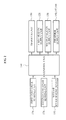
- FIG. 1 illustrates a block diagram of an automatic phosphor mixing apparatus 100 according to example embodiments.
- FIG 2 illustrates a block diagram showing a structure for controlling an operation of the automatic phosphor mixing apparatus 100.
- the automatic phosphor mixing apparatus 100 includes a mixing container 110, a first silicon supply unit 120, a second silicon supply unit 130, phosphor supply units 140, 142, and 144, and a transfer unit 150.
- the mixing container 110 receives a first silicon, a second silicon, and phosphors.
- the mixing container 110 may be a mixing cup having a hollow tube shape, including an inlet formed on an upper surface.
- the mixing container 110 will be explained as a mixing cup hereinafter, embodiments are not limited thereto. That is, various types of containers capable of receiving the first silicon, the second silicon, and the phosphors may be applied.
- the first silicon and the second silicon may be supplied to the mixing container 110 in a liquid state.
- the phosphor may be supplied to the mixing container 110 in a fine powder state.
- the first silicon and the second silicon may be cured into solid silicon only when mixed together.
- the solid silicon may support the phosphor in the form of fine powder.
- the first silicon supply unit 120 may supply the first silicon to an inside of the mixing container 110 up to a predetermined quantity.
- the first silicon supply unit 120 may be disposed on a transfer path of the transfer unit 150.
- the first silicon supply unit 120 may be disposed at an upper part of the transfer unit 150 so as to supply the first silicon to the mixing container 110 provided to the transfer unit 150.
- the second silicon supply unit 130 may supply the second silicon to the inside of the mixing container 110 up to a predetermined quantity.
- the second silicon supply unit 130 may be disposed on the transfer path, of the transfer unit 150.
- the second silicon supply unit 130 may be disposed at the upper part of the transfer unit 150 so as to supply the second silicon to the mixing container 110 provided to the transfer unit 150.
- the first silicon supply unit 120 and the second silicon supply unit 130 may be arranged along the transfer unit at a predetermined distance from each other.
- the first silicon supply unit 120 and the second silicon supply unit 130 according to the present embodiments will be explained as being singular, positions and a number of the first silicon supply unit 120 and the second silicon supply unit 130 are not specifically limited and may be varied according to the design and conditions of the automatic phosphor mixing apparatus 100.
- the phosphor supply units 140, 142, and 144 may supply the phosphors to the inside of the mixing container 110 up to a predetermined quantity.
- the phosphor supply units 140, 142, and 144 may be disposed on the transfer path of the transfer unit 150, and more particularly, at the upper part of the transfer unit 150 to supply the phosphors to the mixing container 110 provided to the transfer unit 150.
- a plurality of phosphor supply units may be provided according to types of the phosphors to be supplied to the mixing container 110.
- the phosphor supply units 140, 142, and 144 may be linearly and separately arranged along the transfer unit of the transfer unit 150. Accordingly, the first silicon supply unit 120, the second silicon supply unit 130, and the phosphor supply units 140, 142, and 144 may be linearly arranged along the transfer path.
- the transfer unit 150 may transfer the mixing container 110 to the first silicon supply unit 120, the second silicon supply unit 130, and the phosphor supply units 140, 142, and 144. Since the first silicon supply unit 120, the second silicon supply unit 130, and the phosphor supply units 140, 142, and 144 are arranged linearly, the transfer path of the transfer unit 150 also has a linear form. Therefore, the transfer unit 150 may transfer the mixing container 110 to the first silicon supply unit 120, the second silicon supply unit 130, and the phosphor supply units 140, 142, and 144 in various orders.
- the transfer unit 150 may be structured in various manners to be capable of stably transferring the mixing container 110.
- the transfer unit 150 may be a conveyer belt system or a robot arm system.
- the transfer unit 150 may include a weight measurement device 152 to measure a weight change of the mixing container 110.
- the weight measurement device 152 may be disposed around a mounting position of the mixing container 110, and may be structured in various manners capable of measuring a weight of the mixing container 110. Therefore, the weight change of the mixing container 110 may be detected in real time during supply of the first silicon, the second silicon, and the phosphors. Consequently, feed quantities of the first silicon, the second silicon, and the phosphors may be detected in real time.
- a control unit 160 of the automatic phosphor mixing apparatus 100 may control the feed quantities with respect to the first silicon supply unit 120, the second silicon supply unit 130, and the phosphor supply unit 140, 142, and 144 in real time, through detection values of the weight measurement device 152.
- the transfer unit 150 transfers the mixing container 110 sequentially to the first silicon supply unit 120, the second silicon supply unit 130, and the phosphor supply units 140, 142, and 144 as described above, the first silicon, the second silicon, and the phosphors are automatically supplied to the inside of the mixing container 110 by the predetermined quantities to the mixing container 110, respectively by the first silicon supply unit 120, the second silicon supply unit 130, and the phosphor supply unit 140, 142, and 144.
- the first silicon, the second silicon, and the phosphors are received in the mixing container 110 by the predetermined quantities, and therefore may be mixed with accurate mixing ratio and accurate mixing quantities.
- the automatic phosphor mixing apparatus 100 may further include a container supply unit 170 and a container discharge unit 172.
- the container supply unit 170 newly supplies an empty mixing container 110 to the transfer unit 150, being disposed at an entrance 150a of the transfer unit 150.
- the container discharge unit 172 may discharge the mixing container 110 in which the first silicon, the second silicon, and the phosphors are received, from the transfer unit 150.
- the container discharge unit 172 may be disposed at an exit 150b of the transfer unit 150.
- the mixing container 110 may be continuously supplied to and discharged from the transfer unit 150, one by one, respectively by the container supply unit 170 and the container discharge unit 172.
- at least five mixing containers 110 may be provided on the transfer path of the transfer unit 150.
- the at least five mixing containers 110 may be simultaneously supplied with the first silicon, the second silicon, and the phosphors by the first silicon supply unit 120, the second silicon supply unit 130, and the phosphor supply units 140, 142, and 144, respectively.
- a mixture of the first silicon, the second silicon and the phosphors received in the mixing container 110 is put into a syringe 180.
- the syringe 180 may inject the mixture into a light emitting diode (LED) package.
- the automatic phosphor mixing apparatus 100 may include container sensing units 174 and 176 adapted to detect the mixing container 110.
- the container sensing units 174 and 176 may include a first container sensing unit 174 to detect the mixing container 110 being supplied from the container supply unit 170 to the transfer unit 150, and a second container sensing unit 176 to detect the mixing container 110 being discharged from the transfer unit 150 to the container discharge unit 172.
- the first container sensing unit 174 may be disposed at a connection portion between the container supply unit 170 and the transfer unit 150.
- the second container sensing unit 176 may be disposed at a connection portion between the container discharge unit 172 and the transfer unit 150. Therefore, whether the mixing container 110 are supplied and discharged, and a number of the mixing container 110 being supplied or discharged may be detected by the first container sensing unit 174 and the second container sensing unit 176.
- the mixing container 110 may be provided with a barcode detected by the first container sensing unit 174 and the second container sensing unit 176.
- the barcode may contain mixing information related to the first silicon, the second silicon, and the phosphors.
- the mixing information may include a feed quantity of the first silicon, a feed quantity of the second silicon, feed quantities of the phosphors, and a serial number of the corresponding mixing container 110.
- the control unit 160 may properly control operations of the transfer unit 150, the first silicon supply unit 120, the second silicon supply unit 130, and the phosphor supply units 140, 142, and 144.
- FIGS. 3 to 5 illustrate diagrams showing various structures of an automatic phosphor mixing apparatus 200 according to other example embodiments.
- FIG. 6 illustrates a sectional view showing a state where phosphors is supplied first to a mixing container of the automatic phosphor mixing apparatus 200 shown in FIGS. 3 to FIG. 5 .
- FIG. 7 illustrates a sectional diagram showing an inside of the mixing container discharged from the automatic phosphor mixing apparatus 200 shown in FIG. 3 .
- FIG. 8 illustrates a sectional diagram showing an inside of the mixing container discharged from the automatic phosphor mixing apparatus 200 shown in FIG. 4 .
- FIG. 9 illustrates a sectional diagram showing an inside of the mixing container discharged from the automatic phosphor mixing apparatus 200 shown in FIG. 5 .
- FIGS. 3 through 9 the same reference numerals used in FIGS. 1 and 2 denote the same elements and structures.
- distinctive features of the automatic phosphor mixing apparatus 200 according to the present embodiments from the automatic phosphor mixing apparatus 100 shown in FIGS. 1 and 2 will be mainly described.
- the automatic phosphor mixing apparatus 200 includes a mixing container 210 configured to receive and discharge the mixture of the first silicon, the second silicon, and accordingly, positions of the first silicon supply unit 120, the second silicon supply unit 130, and the phosphor supply units 140, 142, and 144 are restricted.
- the mixing container 210 may be structured to be capable of both receiving the first silicon, the second silicon, and the phosphors, and discharging the mixture of them.
- the mixing container 210 may be a syringe including an outlet 212 to discharge a mixture of a first silicon S1, a second silicon S2, and phosphors P as shown in FIGS. 6 through 8 .
- the mixing container 210 will be explained as having the syringe form in the present embodiments, any other structures may be applied to the mixing container 210 as far as being capable of storing and discharging the first silicon S1, the second silicon S2, and the phosphors P.
- the mixture of the first silicon S 1, the second silicon S2, and the phosphors P may be injected directly into the LED package using the mixing container 210 discharged from the automatic phosphor mixing apparatus 200. That is, according to the above structure, the mixture does not have to be transferred to an intermediate member, thereby preventing entry of foreign substances and generation of bubbles that may be caused during the transfer.
- the outlet 150b may be disposed at a lower portion of the mixing container 210 whereas an inlet 214 for the first silicon S1, the second silicon S2, and the phosphors P is disposed at an upper portion as shown in FIG 6 . Therefore, when the phosphors P in the fine powder state are supplied to the mixing container 210 first, the phosphors P may be collected to the outlet 150b, thereby clogging the outlet 150b. Also, since the phosphors P may be discharged through the outlet 150b, an error may occur regarding the mixing ratio and the mixing quantities of the first silicon S1, the second silicon S2, and the phosphors P.
- the phosphors P in the phosphor supply units 140, 142, and 144 may be supplied to the mixing container 210 after the first silicon S1 or the second silicon S2 is supplied by at least one of the first silicon supply unit 120 and the second silicon supply unit 130.
- the phosphors P may be prevented from entering the outlet 150b.
- positions of the first silicon supply unit 120, the second silicon supply unit 130, and the phosphor supply units 140, 142, and 144 will be described in detail with reference to FIGS. 3 through 8 .
- the other structures except for the arrangement positions of the first silicon supply unit 120, the second silicon supply unit 130, and the phosphor supply units 140, 142, and 144 are almost the same as in the embodiments of FIGS. 1 and 2 and therefore will not be described again.
- the first silicon supply unit 120 may be disposed in a first position L1 on the transfer path of the transfer unit 150.
- the second silicon supply unit 130 may be disposed in a second position L2 on the transfer path of the transfer unit 150.
- the plurality of phosphor supply units may be provided according to types of the phosphors to be supplied to the mixing container 210.
- the phosphor supply units 140, 142, and 144 may be disposed in positions L3, L4, and L5 linearly and separately along the transfer path.
- the positions and the number of the phosphor supply units may be varied according to a design and conditions of the automatic phosphor mixing apparatus 200.
- the phosphor supply units 140, 142, and 144 may be disposed in the third position L3, the fourth position L4, and the fifth position L5, which are arranged linearly and separately on the transfer path of the transfer unit 150.
- the third position L3, the fourth position L4, and the fifth position L5 may be disposed after at least one of the first position L1 and the second position L2, with respect to a transfer direction of the transfer unit 150. That is, the phosphor supply units 140, 142, and 144 may be disposed after at least one of the first silicon supply unit 120 and the second silicon supply unit 130, with respect to the transfer direction.
- the third position L3, the fourth position L4, and the fifth position L5 may be disposed between the first position L1 and the second position L2, with respect to the transfer direction of the transfer unit 150. That is, the phosphor supply units 140, 142, and 144 may be disposed between the first silicon supply unit 120 and the second silicon supply unit 130.
- any one of the first silicon S1 and the second silicon S2 may be supplied first to the mixing container 210, the phosphors P may be supplied to a surface of the any one of the first silicon S1 and the second silicon S2, and the other one of the first silicon S1 and the second silicon S2 may be supplied finally.
- the third position L3, the fourth position L4, and the fifth position L5 may be disposed after the first position L1 and the second position L2 with respect to the transfer direction. That is, the phosphor supply units 140, 142, and 144 may be disposed after the first silicon supply unit 120 and the second silicon supply unit 130 with respect to the transfer direction.
- the first silicon S1 and the second silicon S2 may be first supplied to the mixing container 210, and the phosphors P may be finally supplied to the surfaces of the first silicon S1 and the second silicon S2.
- At least one of the third position L3, the fourth position L4, and the fifth position L5 may be disposed between the first position L1 and the second position L2 while the others are disposed after the first position L1 and the second position L2 with respect to the transfer direction.
- at least one of the phosphor supply units 140, 142, and 144 may be disposed between the first silicon supply unit 120 and the second silicon supply unit 130 while the others may be disposed after the first silicon supply unit 120 and the second silicon supply unit 130.
- any one of the first silicon S1 and the second silicon S2 is supplied first to the phosphor 210, and a part P1 of the phosphors P is supplied to a surface of the any one of the first silicon S1 and the second silicon S2.
- the other one of the first silicon S1 first silicon S1 and the second silicon S2 is supplied, and the other part P2 of the phosphors P is finally supplied to a surface of the other one of the first silicon S1 and the second silicon S2.
- FIG. 10 illustrates a flowchart showing a mixing method of the automatic phosphor mixing apparatus shown in FIG 3 .
- the method will be described about a case where a plurality of the mixing containers 210 are used.
- the container supply unit 170 supplies the mixing containers 210 to the inlet 150a of the transfer unit 150 in operation 10.
- the container supply unit 170 may supply the mixing containers 210, to the transfer 150 continuously by a predetermined time period.
- the first container sensing unit 174 detects the mixing containers 210 being supplied to the transfer unit 150 in operation 11. During this, the first container sensing unit 174 may detect barcodes formed on the mixing containers 210 in operation 12.
- the feed quantities of the first silicon, the second silicon, and the phosphors are set using mixing information of the barcodes detected by the first container sensing unit 174. That is, in operation 13, the mixing information detected from the barcodes of the mixing containers 210 may be transmitted to the control unit 160.
- the control unit 160 sets the feed quantities using the mixing information.
- the transfer unit 150 transfers the mixing containers 210 sequentially to the first silicon supply unit 120, the second silicon supply unit 130, and the phosphor supply units 140, 142, and 144. During this, when the mixing containers 210 are detected by the first container sensing unit 174, the transfer unit 150 is operated to transfer the mixing containers 210 from the inlet 150a to the outlet 150b of the transfer unit 150. The mixing containers 210 pass through all of the first silicon supply unit 120, the second silicon supply unit 130, and the phosphor supply units 140, 142, and 144.
- the silicon supply unit 120, the second silicon supply unit 130, and the phosphor supply units 140, 142, and 144 supply the first silicon, the second silicon, and the phosphors to the mixing container 210 respectively to predetermined quantities.
- operations 15 to 20 may include operations 15 and 16 to supply the first silicon to the predetermined quantity by the first silicon supply unit 120, operations 19 and 20 to supply the second silicon to the predetermined quantity, by the second supply unit 130, and operations 17 and 18 to supply the phosphors to the predetermined quantity by the phosphor supply units 140, 142, and 144.
- the supplying of the phosphors may be performed after at least one of the supplying of the first silicon or the supplying of the second silicon. According to the example embodiments as shown in FIGS. 3 through 10 , operations 17 and 18 to supply the phosphors are performed between operations 15 and 16 to supply the first silicon and operations 19 and 20 to supply the second silicon.
- the weight measurement device 152 of the transfer unit 150 may measure the weight change of the mixing containers 210 in real time.
- the control unit 160 may control the operations of the first silicon unit 120, the second silicon unit 130, and the phosphor supply units 140, 142, and 144 in real time, according to the weight change of the mixing containers 210.
- the feed quantities for the first silicon unit 120, the second silicon unit 130, and the phosphor supply units 140, 142, and 144 may be predetermined by the control unit 160, according to the mixing information contained in the barcode of the mixing containers 210.
- the control unit 160 may control feeding time of the first silicon unit 120, the second silicon unit 130, and the phosphor supply units 140, 142, and l44 according to the predetermined feed quantities, thereby controlling the feed quantities of the first silicon, the second silicon, and the phosphors.
- the control unit 160 may check actual feed quantities of the first silicon, the second silicon, and the phosphors being supplied to the mixing containers 210 in real time, using detection values of the weight measurement device 152. Therefore, the operations of the first silicon unit 120, the second silicon unit 130, and the phosphor supply units 140, 142, and 144 may be properly controlled in real time.
- the second container sensing unit 176 may detect the mixing containers 210 being discharged through the outlet 150b of the transfer unit 150, in operations 21 and 22. In operations 21 and 22, specifically, the second container sensing unit 176 may detect the mixing containers 210 being discharged from the transfer unit 150 to the container discharge unit 172.
- the container discharge unit 172 discharges the mixing containers 210 receiving the first silicon, the second silicon, and the phosphors to the outside in operation 23.
- the mixing containers 210 passed through the first silicon unit 120, the second silicon unit 130, and the phosphor supply units 140, 142, and 144 are discharged to the outside of the automatic phosphor mixing apparatus 200.
- the control unit 160 may determine whether any of the mixing containers 210 are present in the transfer unit 150, by comparing detection values of the first container sensing unit 174 and the second container sensing unit 176. When the mixing container 210 detected by the first container sensing unit 174 is also detected by the second container sensing unit 176, the control unit 160 may determine that the transfer unit 150 is transferring none of the mixing containers 210 and stop the operation of the transfer unit 150, in operation 24.
- the mixing containers 210 When the mixing containers 210 are completely discharged, out of the automatic phosphor mixing apparatus 200, the mixture of the first silicon, the second silicon, and the phosphors may be injected in the LED package using the mixing containers 210 having the syringe form.
Landscapes
- Chemical & Material Sciences (AREA)
- Chemical Kinetics & Catalysis (AREA)
- Engineering & Computer Science (AREA)
- Materials Engineering (AREA)
- Organic Chemistry (AREA)
- Inorganic Chemistry (AREA)
- Luminescent Compositions (AREA)
- Processing And Handling Of Plastics And Other Materials For Molding In General (AREA)
- Led Device Packages (AREA)
- Accessories For Mixers (AREA)
Applications Claiming Priority (1)
| Application Number | Priority Date | Filing Date | Title |
|---|---|---|---|
| KR1020100112630A KR101107851B1 (ko) | 2010-11-12 | 2010-11-12 | 형광체 자동 배합기 및 형광체 자동 배합 방법 |
Publications (2)
| Publication Number | Publication Date |
|---|---|
| EP2452996A2 true EP2452996A2 (fr) | 2012-05-16 |
| EP2452996A3 EP2452996A3 (fr) | 2012-05-30 |
Family
ID=45218239
Family Applications (1)
| Application Number | Title | Priority Date | Filing Date |
|---|---|---|---|
| EP11188917A Withdrawn EP2452996A3 (fr) | 2010-11-12 | 2011-11-14 | Appareil et procédé pour le mélange automatique de phosphore |
Country Status (5)
| Country | Link |
|---|---|
| US (1) | US9109154B2 (fr) |
| EP (1) | EP2452996A3 (fr) |
| KR (1) | KR101107851B1 (fr) |
| CN (1) | CN102463061B (fr) |
| TW (1) | TWI445574B (fr) |
Cited By (1)
| Publication number | Priority date | Publication date | Assignee | Title |
|---|---|---|---|---|
| EP3085437A1 (fr) * | 2015-04-20 | 2016-10-26 | INKMAKER S.r.l. | Système et procédé de distribution de fluides, en particulier de fluides colorés |
Families Citing this family (4)
| Publication number | Priority date | Publication date | Assignee | Title |
|---|---|---|---|---|
| KR101107851B1 (ko) * | 2010-11-12 | 2012-02-07 | 삼성엘이디 주식회사 | 형광체 자동 배합기 및 형광체 자동 배합 방법 |
| KR101340803B1 (ko) | 2012-06-29 | 2013-12-11 | 세메스 주식회사 | 실리콘 및 형광체 배합 장치 |
| KR101362584B1 (ko) * | 2012-09-25 | 2014-02-13 | 세메스 주식회사 | 실리콘 및 형광체 배합 장치 |
| KR101535740B1 (ko) * | 2014-01-27 | 2015-07-09 | 세메스 주식회사 | 형광체 공급 방법 |
Family Cites Families (54)
| Publication number | Priority date | Publication date | Assignee | Title |
|---|---|---|---|---|
| US2548106A (en) * | 1951-04-10 | Unitfd statfs patfnt offitf | ||
| US1812604A (en) * | 1928-10-03 | 1931-06-30 | Fuller Co | Mixing and blending system |
| US2571655A (en) * | 1947-12-13 | 1951-10-16 | Gen Motors Corp | Apparatus for mixing rubber compounds and the like |
| US2925184A (en) * | 1955-06-07 | 1960-02-16 | Proctor & Schwartz Inc | Apparatus for feeding bulk material to plural supply locations |
| US3877683A (en) * | 1974-03-22 | 1975-04-15 | Scm Corp | Batch tinting apparatus |
| US4277184A (en) * | 1979-08-14 | 1981-07-07 | Alan Solomon | Disposable orthopedic implement and method |
| IN160116B (fr) * | 1982-12-11 | 1987-06-27 | Satake Eng Co Ltd | |
| US4525071A (en) * | 1984-05-31 | 1985-06-25 | Crawford & Russell, Inc. | Additive inventory control, batching and delivery system |
| IT1210567B (it) | 1987-04-22 | 1989-09-14 | Color Service Srl | Impianto di pesatura automatica per coloranti in polvere. |
| US5268849A (en) * | 1989-11-06 | 1993-12-07 | Dunn-Edwards Corporation | Process and apparatus for dispensing liquid colorants into a paint can, and quality control therefor |
| US5468110A (en) * | 1990-01-24 | 1995-11-21 | Automated Healthcare, Inc. | Automated system for selecting packages from a storage area |
| CA2113545A1 (fr) | 1991-07-17 | 1993-02-04 | Timothy J. Perry | Methode amelioree de separation et de recuperation de particules de lampes fluorescentes broyees et appareil connexe |
| IT1272103B (it) * | 1993-03-17 | 1997-06-11 | I A S Ind Automation Systems A | Apparecchiatura per l'erogazione di una sostanza fluida,in quantita' dosate |
| IT1265210B1 (it) * | 1993-11-22 | 1996-10-31 | Ind Automation Systems | Apparecchiatura per l'erogazione di sostanze fluide da miscelare |
| US6188936B1 (en) * | 1995-12-11 | 2001-02-13 | Maguire Products Inc | Gravimetric blender with operatively coupled bar code reader |
| US5992686A (en) * | 1998-02-27 | 1999-11-30 | Fluid Research Corporation | Method and apparatus for dispensing liquids and solids |
| US6196712B1 (en) * | 1998-08-05 | 2001-03-06 | Elm Gunter Von | Bar having an integral cocktail mixer |
| US6698462B2 (en) * | 2001-04-30 | 2004-03-02 | Hewlett-Packard Development Company, L.P. | Automatic solution dispenser |
| US6769462B2 (en) * | 2002-04-03 | 2004-08-03 | E. I. Du Pont De Nemours And Company | Dispensing apparatus |
| CN2544795Y (zh) | 2002-04-26 | 2003-04-16 | 彩虹彩色显像管总厂 | 腐蚀性溶液与水混合装置 |
| JP3969204B2 (ja) | 2002-06-18 | 2007-09-05 | コニカミノルタホールディングス株式会社 | 蛍光体前駆体製造装置及び蛍光体前駆体の製造方法 |
| US6915823B2 (en) * | 2002-12-03 | 2005-07-12 | Forhealth Technologies, Inc. | Automated apparatus and process for reconstitution and delivery of medication to an automated syringe preparation apparatus |
| US7341676B2 (en) | 2004-03-10 | 2008-03-11 | Konica Minolta Holdings, Inc. | Manufacturing method of silicate-containing phosphor and silicate-containing phosphor precursor |
| SE528575C2 (sv) * | 2004-09-27 | 2006-12-19 | Texo Applic Ab | Metod och anordning för automatiserad färgblandning |
| JP4892193B2 (ja) | 2005-03-01 | 2012-03-07 | Dowaホールディングス株式会社 | 蛍光体混合物および発光装置 |
| KR100696937B1 (ko) | 2005-07-29 | 2007-03-20 | 주식회사 탑 엔지니어링 | 디스펜싱 장치용 실린지 및 그 조립방법 |
| US8777479B2 (en) * | 2008-10-13 | 2014-07-15 | Dfine, Inc. | System for use in bone cement preparation and delivery |
| EP1785352B1 (fr) * | 2005-11-15 | 2009-06-24 | L'AIR LIQUIDE, Société Anonyme pour l'Etude et l'Exploitation des Procédés Georges Claude | Procédé et appareil pour le refroidissement de produits alimentaires |
| US7543979B2 (en) * | 2006-03-15 | 2009-06-09 | Neng-Kuei Yeh | Measuring apparatus for micro-amount of materials |
| US7784503B2 (en) * | 2006-09-29 | 2010-08-31 | Momentive Performance Materials | Viscous material metering system and method |
| US7900658B2 (en) * | 2006-10-20 | 2011-03-08 | Fht, Inc. | Automated drug preparation apparatus including drug vial handling, venting, cannula positioning functionality |
| CN201052454Y (zh) | 2006-10-30 | 2008-04-30 | 天津新技术产业园区中核防水材料有限公司 | 环保型全自动粉体制备系统 |
| FR2910452A1 (fr) * | 2006-12-22 | 2008-06-27 | Jean Pierre Solignac | Machine pour la production automatisee de compostions de matieres premieres telle que liquides; poudres, ou pates dans une cuve transportable. |
| CN201001925Y (zh) | 2007-01-26 | 2008-01-09 | 郭温贤 | 干粉灭火器自动灌装生产线 |
| KR100880638B1 (ko) | 2007-07-06 | 2009-01-30 | 엘지전자 주식회사 | 발광 소자 패키지 |
| JP2009025248A (ja) * | 2007-07-23 | 2009-02-05 | Olympus Corp | 自動分析装置及び分注方法 |
| US8827542B2 (en) * | 2008-07-28 | 2014-09-09 | Ganado Technologies Corp. | Apparatus and method to feed livestock |
| US8408257B2 (en) * | 2007-11-09 | 2013-04-02 | Hitachi Aloka Medical, Ltd. | Liquid medicine dispensing device |
| US7972056B2 (en) * | 2007-12-19 | 2011-07-05 | Jean Lontoc | Machine for mixing hair colors |
| DE102008010751A1 (de) * | 2008-02-23 | 2009-08-27 | Bayer Materialscience Ag | Verfahren und Vorrichtung zur Herstellung von Mischungen |
| IT1396371B1 (it) * | 2009-01-14 | 2012-11-19 | Beauty & Business S R L | Dispositivo di pesatura automatica dei coloranti per tinture per capelli e relativo impianto. |
| TWI362968B (en) * | 2009-03-17 | 2012-05-01 | Kismart Corp | Method for spray coating phosphor materials |
| US20100283007A1 (en) | 2009-05-08 | 2010-11-11 | John Russell Robinson | Flexible luminescent paints |
| CN201485258U (zh) | 2009-07-08 | 2010-05-26 | 汪洪波 | 一种墨水囊自动灌装流水线 |
| IT1398989B1 (it) * | 2009-07-10 | 2013-03-28 | Drocco | Linea e metodo di dosaggio e miscelazione per pitture e prodotti. |
| KR100979672B1 (ko) | 2009-09-30 | 2010-09-02 | 주식회사 프로텍 | 발광 다이오드 제조용 형광액 분석 장치 및 분석 방법 |
| US9085449B2 (en) * | 2010-03-08 | 2015-07-21 | The Coca-Cola Company | Aseptic dosing system |
| WO2012005039A1 (fr) * | 2010-07-07 | 2012-01-12 | 株式会社トーショー | Système pour distribuer un médicament |
| WO2012016031A1 (fr) * | 2010-07-28 | 2012-02-02 | Par Systems, Inc. | Systèmes de stockage et de récupération robotiques |
| US20120095595A1 (en) * | 2010-10-14 | 2012-04-19 | Subramanian Krishnan | Process of making cereal, pulse and lentil admixture |
| KR101107851B1 (ko) * | 2010-11-12 | 2012-02-07 | 삼성엘이디 주식회사 | 형광체 자동 배합기 및 형광체 자동 배합 방법 |
| RU2635382C2 (ru) * | 2012-04-13 | 2017-11-13 | ДР. ПИ ИНСТИТЬЮТ ЭлЭлСи | Модульная установка для наполнения и способ |
| JP6134503B2 (ja) * | 2012-09-21 | 2017-05-24 | あおい精機株式会社 | 検体処理装置および検体処理方法 |
| JP6205122B2 (ja) * | 2012-09-21 | 2017-09-27 | あおい精機株式会社 | 検体処理装置 |
-
2010
- 2010-11-12 KR KR1020100112630A patent/KR101107851B1/ko not_active Expired - Fee Related
-
2011
- 2011-10-27 TW TW100139076A patent/TWI445574B/zh not_active IP Right Cessation
- 2011-11-04 US US13/289,693 patent/US9109154B2/en not_active Expired - Fee Related
- 2011-11-10 CN CN201110372579.0A patent/CN102463061B/zh not_active Expired - Fee Related
- 2011-11-14 EP EP11188917A patent/EP2452996A3/fr not_active Withdrawn
Non-Patent Citations (1)
| Title |
|---|
| None |
Cited By (1)
| Publication number | Priority date | Publication date | Assignee | Title |
|---|---|---|---|---|
| EP3085437A1 (fr) * | 2015-04-20 | 2016-10-26 | INKMAKER S.r.l. | Système et procédé de distribution de fluides, en particulier de fluides colorés |
Also Published As
| Publication number | Publication date |
|---|---|
| CN102463061A (zh) | 2012-05-23 |
| TW201233436A (en) | 2012-08-16 |
| KR101107851B1 (ko) | 2012-02-07 |
| EP2452996A3 (fr) | 2012-05-30 |
| TWI445574B (zh) | 2014-07-21 |
| US20120123591A1 (en) | 2012-05-17 |
| CN102463061B (zh) | 2014-08-20 |
| US9109154B2 (en) | 2015-08-18 |
Similar Documents
| Publication | Publication Date | Title |
|---|---|---|
| US9109154B2 (en) | Apparatus and method for automatically mixing phosphor | |
| US9023665B2 (en) | Method and apparatus for manufacturing LED device | |
| US9373553B2 (en) | Resin application apparatus, optical property correction apparatus and method, and method for manufacturing LED package | |
| US20070178010A1 (en) | Fluid content monitor | |
| US9437388B2 (en) | Method and system for dynamic in-situ phosphor mixing and jetting | |
| KR20180032564A (ko) | 고체 입자를 함유하는 액체 재료의 토출 장치 및 토출 방법, 및 도포 장치 | |
| KR101374880B1 (ko) | 엘이디 검사장치 | |
| WO2013121752A1 (fr) | Dispositif d'application de résine et procédé d'application de résine | |
| CN106228231B (zh) | 皮带传输机不同规格物体批量混装传输的计数检测方法 | |
| KR101756114B1 (ko) | 형광체 혼합물 제조 장치 및 형광체 혼합물 제조 방법 | |
| JP5705661B2 (ja) | 液体定量吐出装置及び液体定量吐出方法 | |
| KR100217402B1 (ko) | 리튬전지의 단자 직립정렬장치 | |
| KR101474376B1 (ko) | 온도표시기능을 구비하는 led패키지용 시린지 및 이를 이용하는 led패키지 제조방법 | |
| US20120316665A1 (en) | Led package manufacturing system | |
| KR101938606B1 (ko) | Led 패키지 검사 및 제조 장치 및 그 방법 | |
| CN101980007A (zh) | 一种基于led灯多光路切换的比色系统 | |
| KR100979672B1 (ko) | 발광 다이오드 제조용 형광액 분석 장치 및 분석 방법 | |
| KR101990829B1 (ko) | Led 패키지 검사 및 제조 장치 및 그 방법 | |
| KR20130080609A (ko) | 인라인 타입의 엘이디 검사시스템 및 이의 제어방법 | |
| KR101600621B1 (ko) | 태핑수단을 구비하는 형광체 배합장치 | |
| CN207823326U (zh) | Led配粉点粉机 | |
| KR102186702B1 (ko) | Led 패키지 검사 및 제조 장치 및 그 방법 | |
| CN218769593U (zh) | Led封装装置 | |
| KR101535740B1 (ko) | 형광체 공급 방법 | |
| KR20120075105A (ko) | 형광물질 토출장치 |
Legal Events
| Date | Code | Title | Description |
|---|---|---|---|
| PUAL | Search report despatched |
Free format text: ORIGINAL CODE: 0009013 |
|
| PUAI | Public reference made under article 153(3) epc to a published international application that has entered the european phase |
Free format text: ORIGINAL CODE: 0009012 |
|
| 17P | Request for examination filed |
Effective date: 20111114 |
|
| AK | Designated contracting states |
Kind code of ref document: A2 Designated state(s): AL AT BE BG CH CY CZ DE DK EE ES FI FR GB GR HR HU IE IS IT LI LT LU LV MC MK MT NL NO PL PT RO RS SE SI SK SM TR |
|
| AX | Request for extension of the european patent |
Extension state: BA ME |
|
| AK | Designated contracting states |
Kind code of ref document: A3 Designated state(s): AL AT BE BG CH CY CZ DE DK EE ES FI FR GB GR HR HU IE IS IT LI LT LU LV MC MK MT NL NO PL PT RO RS SE SI SK SM TR |
|
| AX | Request for extension of the european patent |
Extension state: BA ME |
|
| RIC1 | Information provided on ipc code assigned before grant |
Ipc: C09K 11/02 20060101AFI20120424BHEP Ipc: B01F 5/00 20060101ALI20120424BHEP |
|
| RAP1 | Party data changed (applicant data changed or rights of an application transferred) |
Owner name: SAMSUNG ELECTRONICS CO., LTD. |
|
| 17Q | First examination report despatched |
Effective date: 20140314 |
|
| RIC1 | Information provided on ipc code assigned before grant |
Ipc: C09K 11/02 20060101AFI20160628BHEP Ipc: B01F 15/04 20060101ALI20160628BHEP Ipc: B01F 5/00 20060101ALI20160628BHEP Ipc: B01F 13/10 20060101ALI20160628BHEP |
|
| STAA | Information on the status of an ep patent application or granted ep patent |
Free format text: STATUS: THE APPLICATION IS DEEMED TO BE WITHDRAWN |
|
| 18D | Application deemed to be withdrawn |
Effective date: 20161116 |