EP2453069A2 - Moyen de connexion pour treillis - Google Patents
Moyen de connexion pour treillis Download PDFInfo
- Publication number
- EP2453069A2 EP2453069A2 EP11009071A EP11009071A EP2453069A2 EP 2453069 A2 EP2453069 A2 EP 2453069A2 EP 11009071 A EP11009071 A EP 11009071A EP 11009071 A EP11009071 A EP 11009071A EP 2453069 A2 EP2453069 A2 EP 2453069A2
- Authority
- EP
- European Patent Office
- Prior art keywords
- hinged
- truss
- circular
- links
- hinged part
- Prior art date
- Legal status (The legal status is an assumption and is not a legal conclusion. Google has not performed a legal analysis and makes no representation as to the accuracy of the status listed.)
- Withdrawn
Links
- 229910000831 Steel Inorganic materials 0.000 claims abstract description 49
- 239000010959 steel Substances 0.000 claims abstract description 49
- 210000002105 tongue Anatomy 0.000 claims description 31
- 238000000034 method Methods 0.000 description 14
- 230000008569 process Effects 0.000 description 13
- 230000003044 adaptive effect Effects 0.000 description 7
- 230000008901 benefit Effects 0.000 description 6
- 238000009826 distribution Methods 0.000 description 3
- 238000004519 manufacturing process Methods 0.000 description 3
- 241001423398 Ruscus hypoglossum Species 0.000 description 2
- 238000012856 packing Methods 0.000 description 2
- 238000003466 welding Methods 0.000 description 2
- 229910000838 Al alloy Inorganic materials 0.000 description 1
- XUIMIQQOPSSXEZ-UHFFFAOYSA-N Silicon Chemical compound [Si] XUIMIQQOPSSXEZ-UHFFFAOYSA-N 0.000 description 1
- 230000008859 change Effects 0.000 description 1
- 230000000694 effects Effects 0.000 description 1
- 239000000463 material Substances 0.000 description 1
- 230000007246 mechanism Effects 0.000 description 1
- 229910052751 metal Inorganic materials 0.000 description 1
- 239000002184 metal Substances 0.000 description 1
- 230000004048 modification Effects 0.000 description 1
- 238000012986 modification Methods 0.000 description 1
- 229910052710 silicon Inorganic materials 0.000 description 1
- 239000010703 silicon Substances 0.000 description 1
- 238000003860 storage Methods 0.000 description 1
Images








Classifications
-
- E—FIXED CONSTRUCTIONS
- E04—BUILDING
- E04C—STRUCTURAL ELEMENTS; BUILDING MATERIALS
- E04C3/00—Structural elongated elements designed for load-supporting
- E04C3/005—Girders or columns that are rollable, collapsible or otherwise adjustable in length or height
-
- E—FIXED CONSTRUCTIONS
- E04—BUILDING
- E04C—STRUCTURAL ELEMENTS; BUILDING MATERIALS
- E04C3/00—Structural elongated elements designed for load-supporting
- E04C3/02—Joists; Girders, trusses, or trusslike structures, e.g. prefabricated; Lintels; Transoms; Braces
- E04C3/04—Joists; Girders, trusses, or trusslike structures, e.g. prefabricated; Lintels; Transoms; Braces of metal
- E04C3/08—Joists; Girders, trusses, or trusslike structures, e.g. prefabricated; Lintels; Transoms; Braces of metal with apertured web, e.g. with a web consisting of bar-like components; Honeycomb girders
-
- E—FIXED CONSTRUCTIONS
- E04—BUILDING
- E04C—STRUCTURAL ELEMENTS; BUILDING MATERIALS
- E04C3/00—Structural elongated elements designed for load-supporting
- E04C3/02—Joists; Girders, trusses, or trusslike structures, e.g. prefabricated; Lintels; Transoms; Braces
- E04C3/04—Joists; Girders, trusses, or trusslike structures, e.g. prefabricated; Lintels; Transoms; Braces of metal
- E04C2003/0486—Truss like structures composed of separate truss elements
- E04C2003/0495—Truss like structures composed of separate truss elements the truss elements being located in several non-parallel surfaces
Definitions
- the present invention relates to the application of metal frames such as stage lighting stands, display racks for exhibition and building structures, etc., in particular, to a truss connecting means respectively carrier, bearer, bearing or supporter connecting means, by which trusses can be folded and/or extended.
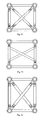
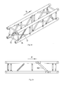
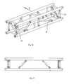
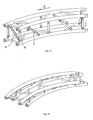
- FIG. 1 and Figure 2 A known straight truss and a curved truss are shown in Figure 1 and Figure 2 .
- the aluminium alloy truss is formed by welding four large main tubes and many small additional tubes, with light weight and high strength. Welded at both ends of the main tubes are tapered sockets with tapered pin holes on it; special taper pins and steel pins are used to insure the high strength connection between the trusses as well as the truss and the square joint.
- the shown truss can not be folded due to the fixed connection between the main tube 100 and the additional tube 200.
- the distribution and the surface processing of the truss will cost much more than the foldable truss of the present invention, which takes up less volume after being disassembled, and thus saves energy in production.
- after the surface processing is conducted it will be difficult for the trusses shown in Figure 1 and Figure 2 to be connected together. Even if large trusses are managed to be assembled, it still requires complicated technology and consumes a lot of materials.
- the curved truss for example, has even larger packing volume, which prohibits its widespread use.
- the packing volume will be significantly reduced, which reduces the cost in production, distribution and other procedures.
- the object of the present invention is to provide a truss connecting means, by which a truss can be folded and extended.
- the present invention provides a truss connecting means which includes main tubes and hinged links, the main tubes are connected by the hinged links, the hinged link includes first hinged parts, second hinged parts, steel pins and a circular tube, both ends of the circular tube are connected respectively to the second hinged part, while the second hinged part is hinged to the first hinged part by the steel pin.
- a groove can be provided on one end of the first hinged part while a tongue can be provided on one end of the second hinged part, alternatively, a tongue is provided on one end of the first hinged part and a groove is provided on one end of the second hinged part alternatively, the hinged portions of the first hinged part and the second hinged part are the same, i.e. both are grooves or tongues.
- the truss connecting means can also comprise a rotatable base. At least one end of the first part can be provided with a circular stem having a circular hole, and the circular stem is engaged into the rotatable base by means of a steel pin passing through the circular hole.
- the truss connecting means can also comprise a rotatable base, the outer surface of which is provided with a groove. At least one end of the first part can be provided with a circular stem having a circular hole and the circular stem is engaged into the groove of the rotatable base by means of a steel pin passing through the circular hole.
- the truss connecting means can also comprise an expansion link, at least one end of the expansion link is engaged into the circular tube, a steel pin passes through the circular hole of the circular tube.
- the other end of the expansion link can be provided with the second hinged part, which is connected with the other end of the circular tube.
- the truss connecting means can also include an expansion link and a rotatable base.
- at least one end of the first hinged part is provided with a circular stem having a circular hole.
- the circular stem is engaged into the rotatable base by the steel pin passing through the circular hole.
- the one end of the expansion link can be engaged into the circular tube; a steel pin passes through the circular hole of the circular tube.
- the other end of the expansion link is provided with the second hinged part, which is connected with the other end of the circular tube.
- the truss connecting means can also include an expansion link and a rotatable base, and the outer surface of the rotatable base can be provided with a groove.
- the at least one end of the first hinged part can be provided with a circular stem having a circular hole on it, and the circular stem can be engaged into the groove of the rotatable base by the steel pin passing through the circular hole of the circular tube.
- One end of the expansion tube can be engaged into the circular tube, and a steel pin passes through the circular hole of the circular tube; the other end of the expansion link can be provided with the second hinged part, which is connected with the other end of the circular tube.
- the hinged links of the present invention can be straight hinged links or tilted hinged links, or diagonal hinged links.
- the straight hinged links and the extendable tilted hinged links when folding longitudinally along the axis direction of the main tube, can be arranged alternately, and the tilting direction of the tilted links is in accordance with the folding direction.
- the forward tilted links and the reverse tilted links can be arranged alternately, and the extendable tilted hinged links are in the same direction.
- trusses in the forward folding direction and trusses in the reverse folding direction can be alternately connected.
- the corresponding main tubes of the two folding planes can be parallel to each other.
- the present invention has the advantages that it provides an easy and fast way to fold a truss and to optimize the forces exerted on the truss; the folded volume has been reduced, which saves a lot fees in transportation and storage. Although there are some other ways to get the similar folding effect, the folding manner of the present invention can achieve a greater volume reducing ratio, and is more convenient to use.
- the exterior of the folded truss is much similar to known fixed truss, of which the aesthetic appearance also promotes its use.
- the taper pin connecting structure and the square joint of the foldable truss are the same with that of the known fixed truss. Therefore, the foldable truss and the fixed truss can be combined together, which ensures the compatible connecting of the fixed truss, the foldable truss and the square joint, which gains economic benefit while saves the investment.
- the truss according to the present invention can be made in a larger size without increasing the volume too much the volume reducing ratio is very large. Therefore, the load carrying capacity of the truss is enhanced with a safer truss structure.
- the volume reducing ratio of the present invention will be increasing for large truss or its components; accordingly, the benefit it brings will be more significant.
- the folding structure as described in the present invention can be widely used in the fields of e.g. stage lighting stands, display and exhibition and trade shows, and can gain better economic benefits.
- stage lighting stands e.g. stage lighting stands
- display and exhibition and trade shows e.g., display and exhibition and trade shows
- the folding manner of the present invention is adopted to significantly reduce the volume of the truss, and hence to strengthen the structure of the products and reduce workload in the field.
- the four faces of a square truss are subject to different forces in use, especially when the truss is used as a beam which requires high strength.
- the forces exerted on two of its four faces are larger than that on the other two faces.
- the truss connecting means of the present invention mainly includes the following components: the first fixed hinged link A, the rotatable hinged link B, the rotation-limited hinged link C, the extendable-retractable fixed hinged link D, the extendable-retractable rotatable hinged link E, the extendable-retractable rotation-limited hinged link F and the second fixed hinged link G, etc.
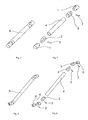
- Figure 3 is a structural drawing of the first fixed hinged link A of the present invention.
- FIG 4 is an exploded view of the first fixed hinged link A of Figure 3 .
- the first fixed hinged link A includes a first hinged part 1, a second hinged part 2, a steel pin and a first circular tube 4.
- the two ends of the first circular tube 4 are respectively fixed connected to the second hinged part 2; the tongue of the second hinged part 2 is adaptively connected with the groove of the first hinged part 1, while the steel pin 3 passes through the groove of the first hinged part 1 and the tongue of the second hinged part 2 as a fixed shaft about which the first hinged part 1 and the second hinged part 2 are rotatable connected.
- the first fixed hinged link as shown in Figure 3 can swing in a plane, and its hinge structure can be vertical or tilted.
- Figure 5 is a structural drawing of the rotatable hinged link B of the present invention.
- FIG 6 is an exploded view of the rotatable hinged link B of Figure 5 .
- the rotatable hinged link B includes the second hinged part 2, the steel pin 3, the first circular tube 4, the third hinged part 5 and the first rotatable base 6.
- the two ends of the first circular tube 4 are respectively fixed connected to the second hinged part 2; the tongue of the second hinged part 2 is adaptive connected with the groove of the third hinged part 5, while the steel pin 3 passes through the groove of the third hinged part 5 and the tongue of the second hinged part 2 as a fixed shaft about which the third hinged part 5 and the second hinged part 2 are rotatable connected.
- the other end of the third hinged part 5 is provided with a circular stem having a circular hole in it.
- the circular stem of the third hinged part 5 is received in the first rotatable base 6 and fixed into the bottom of the first rotatable base 6 by the steel pin 3 passing through the circular hole of the circular stem of the third hinged part 5. When the hinge swings, it can rotate around 360 degree.
- Figure 7 is a structural drawing of the rotation-limited hinged link C of the present invention.
- FIG 8 is an exploded view of the rotation-limited hinged link C of Figure 7 .
- the rotation-limited hinged link C includes the second hinged part 2, the steel pin 3, the first circular tube 4, the third hinged part 5 and the second rotatable base 7.
- the two ends of the first circular tube 4 are respectively fixed connected to the second hinged part 2; the tongue of the second hinged part 2 is adaptive connected with the groove of the third hinged part 5, while the steel pin 3 passes through the groove of the third hinged part 5 and the tongue of the second hinged part 2 as a fixed shaft about which the third hinged part 5 and the second hinged part 2 are rotatable connected.
- the other end of the third hinged part 5 is provided with a circular stem having a circular hole in it; the circular stem of the third hinged part 5 is received into the second rotatable base 7, and the steel pin 3 passes through the circular hole of the circular stem of the third hinged part 5 and the groove of the second rotatable base 7.
- the width of the groove determines the rotation angle of the steel pin 3, that is, the groove underneath the second rotatable base 7 is used to limit the rotation angle of the hinge; the bottom of the second rotatable base 7 is connected with the main tube.
- the third hinged part 5 rotates within a limited angle relative to the second rotatable base 7.
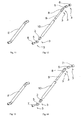
- Figure 9 is a structural drawing of the extendable-retractable fixed hinged link D of the present invention
- Figure 10 is an exploded view of the extendable-retractable fixed hinged link D of Figure 9 .
- the extendable-retractable fixed hinged link D includes the first hinged part 1, the second hinged part 2, the steel pin 3, the expansion link 9 and the second circular tube 10.
- One end of the second circular tube 10 is fixed to the second hinged part 2; the tongue of the second hinged part 2 is adaptive connected with the groove of the first hinged part 1, while the steel pin 3 passes through the groove of the first hinged part 1 and the tongue of the second hinged part 2 as a fixed shaft about which the first hinged part 1 and the second hinged part 2 are rotatably connected.
- One end of the expansion link 9 is provided with the fourth hinged part 8; the tongue of the fourth hinged part 8 is adaptively connected with the groove of the first hinged part 1, while the steel pin 3 passes through the groove of the first hinged part 1 and the tongue of the fourth hinged part 8 as a fixed shaft about which the first hinged part 1 and the fourth hinged part 8 are rotatable connected.
- the other end of the fourth hinged part 8 is a circular stem having a circular hole in it.
- the expansion link 9 can slidably extend and retract inside the second circular tube 10; therefore, when the expansion link 9 is in touch with the bottom of the second circular tube 10, they are fixed by the steel pin 3 passing through the circular hole in the circular stem of the fourth hinged part 8 and the circular hole in the second circular tube 10.
- the expansion link 9 can extend and retract by sliding inside the second circular tube 10.
- Figure 11 is a structural drawing of the extendable-retractable rotatable hinged link E of the present invention
- Figure 12 is an exploded view of the extendable-retractable rotatable hinged link E of Figure 11 .
- the extendable-retractable rotatable hinged link E includes the second hinged part 2, the steel pin 3, the third hinged part 5, the first rotatable base 6, the fourth hinged part 8, the expansion link 9 and he second circular tube 10.
- One end of the second circular tube 10 is fixed connected to the second hinged part 2; the tongue of the second hinged part 2 is adaptive connected with the groove of the third hinged part 5, while the steel pin 3 passes through the groove of the third hinged part 5 and the tongue of the second hinged part 2 as a fixed shaft about which the third hinged part 5 and the second hinged part 2 are rotatable connected.
- the other end of the third hinged part 5 is provided with a circular stem having a circular hole in it.
- the circular stem of the third hinged part 5 is engaged in the first rotatable base 6 and fixed into the bottom of the first rotatable base 6 by the steel pin 3 passing through the circular hole of the circular stem of the third hinged part 5.
- One end of the expansion link 9 is provided with the fourth hinged part 8; the tongue of the fourth hinged part 8 is adaptive connected with the groove of the third hinged part 5, while the steel pin 3 passes through the groove of the third hinged part 5 and the tongue of the fourth hinged part 8 as a fixed shaft about which the third hinged part 5 and the fourth hinged part 8 are rotatable connected.
- the other end of the third hinged part 5 is provided with a circular stem having a circular hole in it.
- the circular stem of the third hinged part 5 is engaged in the first rotatable base 6 and fixed into the bottom of the first rotatable base 6 by the steel pin 3 passing through the circular hole of the circular stem of the third hinged part 5.
- the other end of the fourth hinged part 8 is a circular stem having a circular hole in it.
- the expansion link 9 can slidably extend and retract inside the second circular tube 10; therefore, when the expansion link 9 is in touch with the bottom of the second circular tube 10, they are fixed by the steel pin 3 passing through the circular hole in the circular stem of the fourth hinged part 8 and the circular hole in the second circular tube 10.
- the expansion link 9 can extend and retract by sliding inside the second circular tube 10. Meanwhile, the third hinged part 5 can also rotate relative to the first rotatable base 6.
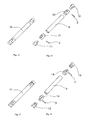
- Figure 13 is a structural drawing of the extendable-retractable rotation-limited hinged link F of the present invention
- Figure 14 is an exploded view of the extendable-retractable rotation-limited hinged link F of Figure 13 .
- the extendable-retractable rotation-limited hinged link F includes the second hinged part 2, the steel pin 3, the third hinged part 5, the second rotatable base 7, the fourth hinged part 8, the expansion link 9 and the second circular tube 10.
- One end of the second circular tube 10 is fixed connected to the second hinged part 2; the tongue of the second hinged part 2 is adaptive connected with the groove of the third hinged part 5, while the steel pin 3 passes through the groove of the third hinged part 5 and the tongue of the second hinged part 2 as a fixed shaft about which the third hinged part 5 and the second hinged part 2 are rotatable connected.
- the other end of the third hinged part 5 is provided with a circular stem having a circular hole in it; said circular stem of the third hinged part 5 is engaged into the second rotatable base 7 and fixed into the groove of the second rotatable base 7 by the steel pin 3 passing through the circular hole of the circular stem of the third hinged part 5.
- the width of the groove determines the rotation angle of the steel pin 3, that is, the groove underneath the second rotatable base 7 is used to limit the rotation angle of the hinge; the bottom of the second rotatable base 7 is connected with the main tube.
- One end of the expansion link 9 is provided with the fourth hinged part 8; the tongue of the fourth hinged part 8 is adaptive connected with the groove of the third hinged part 5, while the steel pin 3 passes through the groove of the third hinged part 5 and the tongue of the fourth hinged part 8 as a fixed shaft about which the third hinged part 5 and the fourth hinged part 8 are rotatable connected.
- the other end of the third hinged part 5 is provided with a circular stem having a circular hole in it.
- the circular stem of the third hinged part 5 is engaged in the second rotatable base 7 and fixed into the groove of the second rotatable base 7 by the steel pin 3 passing through the circular hole of the circular stem of the third hinged part 5.
- the width of the groove determines the rotation angle of the steel pin 3, that is, the groove underneath the second rotatable base 7 is used to limit the rotation angle of the hinge, and the bottom of the second rotatable base 7 is connected with the main tube.
- the third hinged part 5 swings, it rotates in a limited angle relative to and the second rotatable base 7.
- the other end of the fourth hinged part 8 is provided with a circular stem having a circular hole in it.
- the expansion link 9 can slidably extend and retract inside the second circular tube 10; therefore, when the expansion link 9 is in touch with the bottom of the second circular tube 10, they are fixed by the steel pin 3 passing through the circular hole in the circular stem of the fourth hinged part 8 and the circular hole in the second circular tube 10.
- the expansion link 9 can extend and retract by sliding inside the second circular tube 10. Meanwhile, the third hinged part 5 can also rotate within limited angle relative to the second rotatable base 7.
- Figure 15 is a structural drawing of the second fixed hinged link G of the present invention
- Figure 16 is an exploded view of the second fixed hinged link G of Figure 15 .
- the difference between Figure 15, Figure 16 and Figure 3, Figure 4 is that, the first hinged part 1 is a groove while the second hinged part 2 is a tongue; the fifth hinged part 11 is a tongue while the sixth hinged part 12 is a groove.
- the other hinged links can also be provided with this arrangement.
- Figure 17 is a structural drawing of the third fixed hinged link H of the present invention.
- Figure 18 is an exploded view of the third fixed hinged link H of Figure 17 .
- the difference between Figure 17, Figure 18 and Figure 15, Figure 16 is that, the fifth hinged part 11 is a single tongue while the sixth hinged part 12 is a single groove; the hinge part of the seventh hinged part 13 is double-tongue with double-groove, which is the same as the hinge part of the eighth hinged part 14.
- the other hinged links can also be provided with this arrangement.
- the hinge parts of the seventh hinged part 13 and the eighth hinged part 14 can in the form of three-tongue and three-groove, etc., and the present invention is not intended to be restricted to the two forms.
- the arrangement of the hinged links of the present invention is not restricted to the manners as described above.
- the preferred embodiment of the present invention is that in Figure 17 , which is more practical than the two modes as shown in Figure 3 and Figure 15 .
- the first hinged part 1 in Figure 3 is used as the groove and the second hinged part 2 of f Figure 3 is used as the tongue.
- the modes in Figure 15 and Figure 17 will not be described (i.e. the fifth hinged part 11 as the tongue and the sixth hinged part as the groove; the hinges of the seventh hinged part and the eighth hinged part are the same double-tongue or double-groove).
- first hinged part 1 and the fifth hinged part 11 can be tilted, which looks more similar to the welded tilted link of the fixed single pieces of the truss.
- the truss can be folded in the same way while force applied onto the truss is optimized.
- the truss connecting means usually applies to the straight truss and the curved truss.
- the truss connecting means of the present invention may perform better with the straight truss.
- its performance may be influenced, for it is the folded face that bears the forces. Nevertheless, the strength can be enhanced by increasing the diameter of the foldable additional tubes or the wall thickness of the foldable additional tubes. Specific square straight truss and curved truss will be described in the following.
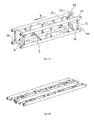
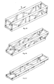
- Figure 19 is a structural drawing of the square truss of the present invention being folded longitudinally.
- There are four main tubes 31, 32, 33 and 34 (there can be more than four main tubes or less than four main tubes depending on actual need, and the present invention is not restricted to that) as well as a number of additional tubes in Figure 19 .
- the additional tube is formed by said first fixed hinged link A, the extendable-retractable fixed hinged link D and the rotation-limited hinged link C; however, the additional tube can be formed by other components, which is not intended to be restricted.
- the extendable-retractable fixed hinged link D of Figure 19 is illustrated by a sectional view, while the rest three extendable-retractable fixed hinged links are not shown in a sectional view.
- the rest of the figures of the present invention also adopt the combination of sectional view.
- the upper single piece which is formed by welding the first main tube 31, the third main tube 33, the first additional tube 21 (straight additional tube) and the second additional tube 22 (tilted additional tube), moves along the X direction, while the third additional tube 40 swings along the X direction about the shaft of the hinge of the first fixed hinged link A. All the straight links formed by the first main tube 31 and the second main tube 32 moves in the way along the X direction.
- the extendible telescopic unit formed by the expansion link 9 and the second circular 10 will be elongated accordingly, and all the tilted links between the first main tube 31 and the second main tube 32 are extending as they swing. All the straight hinged links and the tilted hinged links between the third main tube 33 and the fourth main tube 34 move in the same way.
- the rotation-limited hinged link C rotates as it swings about its shaft along the X direction, until the hinged part of the first main tube 31 is in touch with the second main tube 32.
- the fixed welded single piece formed by the first main tube 31, the third main tube 33, the first additional tube 21 and the second additional tube 22 will move along the X direction until the hinged part of the first main tube 31 is in touch with the second main tube 32, and the hinged part of the third main tube 33 is in touch with the fourth main tube 34; thus the folding process of the truss is completed.
- the folded truss is shown in Figure 20 .
- Figure 21 is the first schematic drawing of the diagonal rotation-limited hinged links of the square truss when being folded longitudinally;
- Figure 22 is the second schematic drawing of the diagonal rotation-limited hinged links of the square truss when being folded longitudinally.
- Figure 23 is one of the schematic drawings of the diagonal rotation-limited hinged links of the rectangular truss when being folded longitudinally; its folding manner is the same as that of the square truss.
- the diagonal rotation-limited hinged links C of the truss as shown in Figure 21 can be parallel or crossed, the latter of which is more commonly used, as adopted in Figure 22 and 23 .
- the neighbouring two diagonal links are crossed in order to enhance the stability of the whole truss structure and to optimize the force distribution.
- all the first fixed hinged links A and all the extendable-retractable fixed hinged links D between the first main tube 31 and the second main tube 32 are within the same plane.
- the first fixed hinged link A and the extendable-retractable fixed hinged link D have to be separated from each other in a certain distance.
- the telescopic tube When the truss is in the opened configuration, i.e. operable configuration as shown in Figure 19 , the telescopic tube is the shortest and is enabled to bear stress.
- the length of the diagonal rotation-limited hinged link C of the square truss will not be changed during the folding process; also, more diagonal links can be added to maintain the overall rigidity of the truss, so as to enhance its load carrying capacity.
- Figure 19 is a structural drawing of the square truss (single-row of additional tubes) of(delete) when being folded longitudinally, and Figure 24 shows another structure of the square truss (double rows of additional tubes) when being folded longitudinally.
- the space between the first fixed hinged link A and the extendable-retractable fixed hinged link D is relatively large, which lowers its load carrying capacity.
- the truss shown in Figure 24 can overcome this drawback, wherein the first fixed hinged link A and the extendable-retractable fixed hinged link D are in two parallel plans with certain distance from each other; therefore, the first fixed hinged link A and the extendable-retractable fixed hinged link D can be alternatively arranged closely.
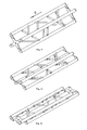
- the tilted links in Figure 19 can be arranged in a staggered arrangement; the reverse tilted link is detachable. When the truss needs to be folded, the shafts of screws at both ends of the reverse tilted link are detached, so as to fold the truss in the same manner as that in the Figure 19 .
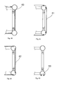
- the reverse tilted link can be in the form of hook link 50 as in the truss shown in Figure 25 , which is easy and fast to be fixed and detached.
- the hook link 50 is easy to be fixed and detached, it may influence the overall appearance of the truss, and may not as simple and practical as the truss shown in Figure 19 .
- Figure 26 is a structural drawing of the square truss of the present invention when being folded laterally.
- the first fixed hinged link A swings about its axis
- the rotatable hinged link B swings in a circle around the axis, while the hinged part of the rotatable hinged link B rotates relative to the rotation base of the hinge.
- the diagonal extendable-retractable fixed hinged link D swings about its axis with its expansion link being extended until the truss is folded.
- the straight link between the two tilted links can be removed, as shown in Figure 27 ; that is, there are several ways for combining the straight links and the tilted links. It should be noted that the axis of the first fixed hinged link A and the axis of the extendable-retractable fixed hinged link D are in the same plane in Figure 26 .
- more straight links and tilted links can be closely arranged in different manners, of which the most commonly used is that similar to the arrangement of the straight links and tilted links in the fixed welded single piece; meanwhile, the strength of the truss is enhanced by increasing the thickness of the wall of the first fixed hinged link A and the extendable-retractable fixed hinged link D or by increasing the diameter of the tubes.
- the rigidity of the truss and its load carrying capacity can be enhanced by adding more diagonal links along the length of the truss and fixing extendable-retractable fixed hinged link D by pins and screws.
- the lateral folding of the rectangle truss is in the same way as that of the square truss.
- the volume of the laterally folded square truss is 30 ⁇ 70% of its original volume; the volume of the longitudinally folded square truss is 30 ⁇ 70% of its original volume.
- the volume of the longitudinally folded square truss is 20% ⁇ 50% smaller than that of the laterally folded square truss; therefore, the longitudinally folding manner is advantageous.
- the volume of the laterally folded truss is not reduced as much as that of the longitudinally folded truss; however, the arrangement of the straight links and the tilted links is not limited by the geometrical condition of the folded truss, which is benefit to load carrying or other special application.
- the longitudinally folding manner as shown in Figure 19 will significantly reduce the volume of the truss, which is more suitable to the circumstances in which small volume is required and the strength of the truss is not very high.
- Figure 28 is a structural drawing illustrating an embodiment of the curved truss of the present invention when being folded longitudinally (i.e. the diagonal link is in the middle symmetric plane of the curved truss). All the straight links of the first fixed hinged links A are perpendicular to the folding direction X, so as to enable all the first fixed hinged links A to swing along the X direction.
- the extendable-retractable rotatable hinged link E swings about its axis along the folding direction X as shown in Figure 29 . Meanwhile, in the folding process, the telescopic tube of the extendable-retractable rotatable hinged link E extends, and its hinged part rotates.
- the geometrical position of the axis of the rotation-limited hinged link C in the middle symmetric plane is shown in Figure 21 .
- the rotation-limited hinged link C rotates (in the same manner with the rotation-limited hinged link C in Figure 19 ) during the folding process, and the folded truss is shown in Figure 30 .
- the extendable-retractable rotation-limited hinged links F i.e. the diagonal links are located at both ends of the curved truss
- the extendable-retractable rotation-limited hinged links F can also be adopted in a curved truss, with the crossing direction as shown in Figure 31 , and the folded truss as shown in Figure 32 .
- the staggered extendable-retractable rotation-limited hinged links F will be extended; if the opposite arrangement is adopted, screws and pins are needed to fix the length of the diagonal links.
- the diagonal links of this embodiment can be connected in various directions, e.g. parallel to the folding direction or parallel to the direction of normal plane of the curved main tubes.
- the diagonal links is extended when being folded along the folding direction as shown in Figure 36 .
- the axis of the hinge of the first fixed hinged link A is perpendicular to the Y direction, with the folding manner the same as that of the above.
- the same folding manner as that of the present invention along the X direction as shown in Figure 37 can be realized if only the corresponding main tube of the two fixed welded single pieces meet the geometrical condition, i.e. being parallel to each other, and the two fixed welded single pieces are of the same size, with their hinges arranged along the folding direction of X as shown.
- main tubes can be connected by the extendable-retractable rotatable hinged links, so as to achieve the corresponding aim of folding.
- steel pins can be used to fix the slidable expansion links of these extendable-retractable rotatable hinged links, and further fix the corresponding links of the truss, so as to form the whole truss structure by connecting a plurality of trusses.
- truss link structure which is formed by retractable straight links (i.e. straight hinged links) and fix-length tilted links (i.e. tilted hinged links), of which the folding manner is the same with that of the fix-length straight links and extendable tilted links.
- retractable straight links i.e. straight hinged links
- fix-length tilted links i.e. tilted hinged links
- the folding manner is the same with that of the fix-length straight links and extendable tilted links.
- the retractable straight links have certain drawbacks and its load carrying capacity is low. Therefore, in the operable configuration, the length of the retractable straight links can be fixed by using screws and pins.
- this structure is not as practical as the folding manner of Figure 19 .
- springs can be used inside the hinges and the expansion links, so as to make the opening and folding process of the truss quicker and more convenient, which makes the truss to be easier to use.
- Figure 33 and 34 are plan views showing the connecting manner of the square truss and the curved truss of the present invention when folded longitudinally.
- the diagonal links are staggered with each other at the neighbouring connecting areas, so as to form a fixed structure by connecting multiple trusses, which possesses a certain capacity of load carrying.
- the folding manner of this type of structure and the certain geometrical position and size adapted to this manner secondly, the alternatively arranged manner following the tilting direction of the extendable-retractable tilted link or the diagonal links, by which two or more straight or curved trusses are connected to form a fixed structure from single movable truss, thus the load carrying capacity of the whole structure is enhanced (including a single truss or multiple trusses, straight or curved foldable and movable trusses, which are connected to the square joints and can also form a fixed structure of the trusses with certain capacity to carry load ); thirdly, the compatibility of the foldable trusses with similar look, the fixed trusses and the square joints to be connect together.
- the trusses can be divided into different types including trusses with taper pin, trusses with telescopic tube, hinged trusses and covered trusses.
- the folding manner is the same with that of the two-tube and four-tube trusses with taper pin as above described.
- the telescopic truss is shown in Figure 41 and 42
- the hinged truss is shown in Figure 43 and 44 .
- Figure 41 is a schematic drawing of the connecting of the telescopic truss of the present invention.
- Figure 42 is a structural drawing showing an embodiment of the telescopic truss of the present invention.
- Figure 43 is a schematic drawing of the connecting of the hinged truss of the present invention.
- Figure 44 is a structural drawing showing an embodiment of the hinged truss of the present invention. The folding manner is the same with the above described.
- Figure 45-47 are schematic drawings illustrating the longitudinally folding process of the covered truss.
- Figure 48-50 are schematic drawings illustrating the laterally folding process of the covered truss.
- Figure 51-56 are schematic drawings illustrating the longitudinally folding process of the covered truss connected by two types of single taper pins.
- Figure 57-59 are schematic drawings illustrating the longitudinally folding process of the covered truss connected by double taper pins.
- the folding manners are similar to the above described.
- the movable link on the cover of the covered folded trusses that are longitudinally or laterally folded is equivalent to the first fixed hinged link as above mentioned.
- the linkage taper pins of the four main tubes are moved to the middle of the section of the truss, which has the following advantages.
- the main tubes can be provided with grooves or tongue edge, which allows the truss to be more decorative, for example, to insert into the truss a decorating board or to fit into it the decorating pictures (as shown in Figure 60 to 63 ).
- the trusses can be divided into the following types: trusses with decorating board inserted into the groove of the main tubes; trusses that using Velcro to attach and remove the decorating board; trusses that using silicon stripes to fix the canvas; trusses provided with guide rail for track lights, etc.
- the taper pins or screws that connecting the trusses are separated from the strip groove or the main tubes with tongue edge, but their folding manners are the same with the above described.
Landscapes
- Engineering & Computer Science (AREA)
- Architecture (AREA)
- Civil Engineering (AREA)
- Structural Engineering (AREA)
- Tents Or Canopies (AREA)
- Joining Of Building Structures In Genera (AREA)
- Extensible Doors And Revolving Doors (AREA)
Applications Claiming Priority (2)
| Application Number | Priority Date | Filing Date | Title |
|---|---|---|---|
| CN2010206095233U CN202024044U (zh) | 2010-11-16 | 2010-11-16 | 桁架连接装置 |
| CN201010546307.3A CN101994897B (zh) | 2010-11-16 | 2010-11-16 | 桁架连接装置 |
Publications (2)
| Publication Number | Publication Date |
|---|---|
| EP2453069A2 true EP2453069A2 (fr) | 2012-05-16 |
| EP2453069A3 EP2453069A3 (fr) | 2015-10-28 |
Family
ID=45098777
Family Applications (1)
| Application Number | Title | Priority Date | Filing Date |
|---|---|---|---|
| EP11009071.9A Withdrawn EP2453069A3 (fr) | 2010-11-16 | 2011-11-15 | Moyen de connexion pour treillis |
Country Status (2)
| Country | Link |
|---|---|
| EP (1) | EP2453069A3 (fr) |
| DE (1) | DE102011011855A1 (fr) |
Cited By (4)
| Publication number | Priority date | Publication date | Assignee | Title |
|---|---|---|---|---|
| CN103343866A (zh) * | 2013-07-24 | 2013-10-09 | 黄凤章 | 可折叠的支承结构 |
| ITPT20130001A1 (it) * | 2013-03-28 | 2014-09-29 | Enrico Mangoni | Sistema modulare e semiprefabbricato in acciaio per la protezione sismica di edifici esistenti. |
| US20190186135A1 (en) * | 2017-12-18 | 2019-06-20 | Tiffin Scenic Studios, Inc. | Connector system for trusses |
| CN116104554A (zh) * | 2023-02-01 | 2023-05-12 | 朱永鹏 | 一种巷道临时支护方法及其支护装置 |
Families Citing this family (1)
| Publication number | Priority date | Publication date | Assignee | Title |
|---|---|---|---|---|
| DE102013016982B4 (de) | 2013-10-14 | 2016-08-04 | Herbert Klebe | Klappmechanismus |
Family Cites Families (3)
| Publication number | Priority date | Publication date | Assignee | Title |
|---|---|---|---|---|
| US4673308A (en) * | 1985-11-29 | 1987-06-16 | Miranda Investments Limited | Hinge mechanism for use with folding structures |
| DE202008001272U1 (de) * | 2008-01-29 | 2009-06-04 | Daas, Kamal | Gittertragwerk |
| CN201556391U (zh) * | 2009-11-25 | 2010-08-18 | 阮子清 | 一种可折叠桁架 |
-
2011
- 2011-02-21 DE DE201110011855 patent/DE102011011855A1/de not_active Withdrawn
- 2011-11-15 EP EP11009071.9A patent/EP2453069A3/fr not_active Withdrawn
Non-Patent Citations (1)
| Title |
|---|
| None |
Cited By (5)
| Publication number | Priority date | Publication date | Assignee | Title |
|---|---|---|---|---|
| ITPT20130001A1 (it) * | 2013-03-28 | 2014-09-29 | Enrico Mangoni | Sistema modulare e semiprefabbricato in acciaio per la protezione sismica di edifici esistenti. |
| CN103343866A (zh) * | 2013-07-24 | 2013-10-09 | 黄凤章 | 可折叠的支承结构 |
| CN103343866B (zh) * | 2013-07-24 | 2015-06-10 | 黄凤章 | 可折叠的支承结构 |
| US20190186135A1 (en) * | 2017-12-18 | 2019-06-20 | Tiffin Scenic Studios, Inc. | Connector system for trusses |
| CN116104554A (zh) * | 2023-02-01 | 2023-05-12 | 朱永鹏 | 一种巷道临时支护方法及其支护装置 |
Also Published As
| Publication number | Publication date |
|---|---|
| DE102011011855A1 (de) | 2012-05-16 |
| EP2453069A3 (fr) | 2015-10-28 |
Similar Documents
| Publication | Publication Date | Title |
|---|---|---|
| EP2453069A2 (fr) | Moyen de connexion pour treillis | |
| CN100460621C (zh) | 折叠式帐篷 | |
| US12570341B2 (en) | Bottom support structure of hand trolley and hand trolley | |
| US12221146B2 (en) | Foldable wagon | |
| US8925565B2 (en) | Hub assembly for a foldable tent | |
| JP6913230B2 (ja) | 折り畳み可能なテント | |
| US8376291B1 (en) | Foldable A-frame carrier | |
| US20240084616A1 (en) | Folding vehicle rooftop tent | |
| RU2663851C1 (ru) | Складная модульная конструкция для палатки или для аналогичного укрытия быстрой установки | |
| US20150020716A1 (en) | Foldable Table | |
| JP2012200596A (ja) | 展開式衣服フレーム | |
| CN101832056A (zh) | 可组合的折叠式帐篷 | |
| US20230157444A1 (en) | Multi-functionalexpandable folding table assembly | |
| US12304543B2 (en) | Folding cart | |
| US20030106871A1 (en) | Telescopic jib for a vehicular crane | |
| US12559149B2 (en) | Foldable cart and foldable cart frame | |
| CN106078680A (zh) | 一种可折展四棱柱框架结构 | |
| US20040255829A1 (en) | Portable folding table | |
| US11297935B2 (en) | Collapsible table | |
| CN109025025A (zh) | 一种可实现双向联动折叠的平面开合屋盖结构 | |
| RU2398084C1 (ru) | Складной шарнирный металлический каркас для мобильных сооружений и укрытий | |
| US6499906B1 (en) | Pivot joint foldable furniture | |
| CN205852781U (zh) | 一种可折展四棱柱框架结构 | |
| US20050044810A1 (en) | Support structure with foldable end cap | |
| KR200165503Y1 (ko) | 절첩식휀스 |
Legal Events
| Date | Code | Title | Description |
|---|---|---|---|
| PUAI | Public reference made under article 153(3) epc to a published international application that has entered the european phase |
Free format text: ORIGINAL CODE: 0009012 |
|
| AK | Designated contracting states |
Kind code of ref document: A2 Designated state(s): AL AT BE BG CH CY CZ DE DK EE ES FI FR GB GR HR HU IE IS IT LI LT LU LV MC MK MT NL NO PL PT RO RS SE SI SK SM TR |
|
| AX | Request for extension of the european patent |
Extension state: BA ME |
|
| PUAL | Search report despatched |
Free format text: ORIGINAL CODE: 0009013 |
|
| AK | Designated contracting states |
Kind code of ref document: A3 Designated state(s): AL AT BE BG CH CY CZ DE DK EE ES FI FR GB GR HR HU IE IS IT LI LT LU LV MC MK MT NL NO PL PT RO RS SE SI SK SM TR |
|
| AX | Request for extension of the european patent |
Extension state: BA ME |
|
| RIC1 | Information provided on ipc code assigned before grant |
Ipc: E04C 3/00 20060101AFI20150918BHEP Ipc: E04C 3/04 20060101ALN20150918BHEP Ipc: E04C 3/08 20060101ALI20150918BHEP |
|
| STAA | Information on the status of an ep patent application or granted ep patent |
Free format text: STATUS: THE APPLICATION IS DEEMED TO BE WITHDRAWN |
|
| 18D | Application deemed to be withdrawn |
Effective date: 20160429 |