EP2453231A2 - Connexion de fibres creuses - Google Patents
Connexion de fibres creuses Download PDFInfo
- Publication number
- EP2453231A2 EP2453231A2 EP11187151A EP11187151A EP2453231A2 EP 2453231 A2 EP2453231 A2 EP 2453231A2 EP 11187151 A EP11187151 A EP 11187151A EP 11187151 A EP11187151 A EP 11187151A EP 2453231 A2 EP2453231 A2 EP 2453231A2
- Authority
- EP
- European Patent Office
- Prior art keywords
- hollow fiber
- connecting element
- ring
- connection
- ring element
- Prior art date
- Legal status (The legal status is an assumption and is not a legal conclusion. Google has not performed a legal analysis and makes no representation as to the accuracy of the status listed.)
- Withdrawn
Links
- 239000000835 fiber Substances 0.000 title claims description 49
- 239000012510 hollow fiber Substances 0.000 claims abstract description 157
- 238000007789 sealing Methods 0.000 claims abstract description 67
- 239000000463 material Substances 0.000 claims description 19
- 230000004323 axial length Effects 0.000 claims description 6
- 238000001825 field-flow fractionation Methods 0.000 claims description 5
- 230000008878 coupling Effects 0.000 claims description 2
- 238000010168 coupling process Methods 0.000 claims description 2
- 238000005859 coupling reaction Methods 0.000 claims description 2
- 238000003825 pressing Methods 0.000 description 36
- 238000009434 installation Methods 0.000 description 9
- 230000007704 transition Effects 0.000 description 8
- 230000000694 effects Effects 0.000 description 6
- 229920003023 plastic Polymers 0.000 description 6
- 239000004033 plastic Substances 0.000 description 6
- 239000013598 vector Substances 0.000 description 6
- 239000012530 fluid Substances 0.000 description 5
- 238000000926 separation method Methods 0.000 description 5
- 230000009471 action Effects 0.000 description 4
- 239000012528 membrane Substances 0.000 description 4
- 230000009467 reduction Effects 0.000 description 4
- 238000005452 bending Methods 0.000 description 3
- 230000015572 biosynthetic process Effects 0.000 description 3
- 150000001875 compounds Chemical class 0.000 description 3
- 238000005520 cutting process Methods 0.000 description 3
- 230000008901 benefit Effects 0.000 description 2
- 230000005540 biological transmission Effects 0.000 description 2
- 239000012876 carrier material Substances 0.000 description 2
- 238000006073 displacement reaction Methods 0.000 description 2
- 238000004128 high performance liquid chromatography Methods 0.000 description 2
- 239000000203 mixture Substances 0.000 description 2
- 239000002904 solvent Substances 0.000 description 2
- 238000000108 ultra-filtration Methods 0.000 description 2
- 239000002318 adhesion promoter Substances 0.000 description 1
- 239000000853 adhesive Substances 0.000 description 1
- 230000001070 adhesive effect Effects 0.000 description 1
- 238000006243 chemical reaction Methods 0.000 description 1
- 239000011248 coating agent Substances 0.000 description 1
- 238000000576 coating method Methods 0.000 description 1
- 230000000295 complement effect Effects 0.000 description 1
- 230000006835 compression Effects 0.000 description 1
- 238000007906 compression Methods 0.000 description 1
- 230000003247 decreasing effect Effects 0.000 description 1
- 239000011521 glass Substances 0.000 description 1
- 210000003128 head Anatomy 0.000 description 1
- 238000001746 injection moulding Methods 0.000 description 1
- 238000005304 joining Methods 0.000 description 1
- 239000007788 liquid Substances 0.000 description 1
- 238000004519 manufacturing process Methods 0.000 description 1
- 238000005259 measurement Methods 0.000 description 1
- 210000001331 nose Anatomy 0.000 description 1
- 230000002093 peripheral effect Effects 0.000 description 1
- 229920000642 polymer Polymers 0.000 description 1
- 229910001220 stainless steel Inorganic materials 0.000 description 1
- 239000010935 stainless steel Substances 0.000 description 1
Images



Classifications
-
- G—PHYSICS
- G01—MEASURING; TESTING
- G01N—INVESTIGATING OR ANALYSING MATERIALS BY DETERMINING THEIR CHEMICAL OR PHYSICAL PROPERTIES
- G01N30/00—Investigating or analysing materials by separation into components using adsorption, absorption or similar phenomena or using ion-exchange, e.g. chromatography or field flow fractionation
- G01N30/0005—Field flow fractionation
-
- G—PHYSICS
- G01—MEASURING; TESTING
- G01N—INVESTIGATING OR ANALYSING MATERIALS BY DETERMINING THEIR CHEMICAL OR PHYSICAL PROPERTIES
- G01N30/00—Investigating or analysing materials by separation into components using adsorption, absorption or similar phenomena or using ion-exchange, e.g. chromatography or field flow fractionation
- G01N30/02—Column chromatography
- G01N30/60—Construction of the column
- G01N30/6004—Construction of the column end pieces
Definitions
- the present invention relates to a hollow fiber connector for one end of a hollow fiber intended for field flow fractionation, comprising a connector having a through-hole for receiving the end of the hollow fiber.
- the hollow fiber takes over the function of a separation channel and samples from mixtures and solvents usually zugsten via a standard port of the high performance liquid chromatography (HPLC) of the hollow fiber or derived from the hollow fiber.
- HPLC high performance liquid chromatography
- the hollow fiber is arranged in a tubular housing or a cartridge, so that the housing or the cartridge surrounds the hollow fiber at a radial distance and thereby a volume is formed between the outside of the hollow fiber and the inside of the housing or the cartridge.
- crossflow occurs, which is to be referred to here as crossflow, and which, for example, due to an overpressure generated within the hollow fiber occurs in the form of filtered fluid emerging from the hollow fiber in the housing.
- the cross-flow forming fluid must not be contaminated, and thus a leak-tight sealing of the hollow fiber, in particular the outer surface of the hollow fiber to the environment is required.
- capillary connections can be provided in order to realize this compromise as well as possible.
- the hollow fiber is heavily punctually loaded, especially at the beginning and end.
- the constriction of the inner diameter of the fiber caused thereby also swirls the sample at the inlet and outlet.
- this deteriorates a precise focusing on the inlet side, in particular according to a flow-related installation of the sample at the desired starting point near the wall of the hollow fiber.
- fractions which have already been separated on the outlet side are again shuffled at such constrictions, and band broadening and asymmetrical peaks occur.
- the above object can be achieved by a hollow fiber connection for one end of a hollow fiber suitable for field flow fractionation, with a connection element having a passage opening for receiving the end of the hollow fiber.
- a mountable on the connecting element ring element wherein the ring member and the connecting element are designed such that the mounting of the ring member on the connecting element a reduction of the cross section of the through hole in the connecting element for a sealing connection of the end of the hollow fiber with a through opening limiting Section of the connecting element causes.
- the fiber can be sealed via a radial pressure, in particular via a type of clamping pressure or pressing force.
- the cross-section of the fiber must not be changed so much.
- the difficulty consists in sealing the fragile hollow fiber in such a way that the fluid sample to be examined can not get into the crossflow and the housing or the cartridge has no leakage to the outside. So it is to find the optimal compromise between maximum holding and sealing action and minimum cross-sectional narrowing.
- a hollow fiber of the type in question is permeable, ie liquid and gas permeable, such a hollow fiber is not to be confused with capillaries or pipe material in the narrower sense.
- a pressing force can be exerted on the connecting element by means of a ring or ring element, in particular a type of cone-pressing ring, which can be targeted to a section in which a radial seal is to take place.
- Ring element and connecting element can together from a connection part be pressed against the end of a housing or tubular housing part.
- a hollow fiber can be sealed in a secure manner by virtue of the force acting externally on the fiber for sealing, e.g. in the form of a clamping pressure, can be predetermined with a correct amount.
- This is particularly advantageous for hollow fibers made of plastics or polymers as carrier material, which must be handled with care, and in which the carrier material can also have a certain porosity, wherein the hollow fibers can also be made of a plastic carrier with ultrafiltration membrane applied at least on the outside. It can be adjusted via the porosity whether and to what extent the hollow fiber in the radial direction is permeable transversely to its fiber longitudinal axis for a fluid or certain fluid components.
- a further advantage of the invention is the fact that it dispenses with any type of adhesives, kit compositions or other adhesion promoters, since these or the auxiliaries contained therein are released by the solvent necessary for the measurement and then can damage the detectors.
- the ring element can be pushed in the assembled state essentially in the fiber longitudinal axis, turned up or placed on the connecting element.
- the section In the assembled state, the section can be brought into contact with the hollow-fiber end on the outside, essentially over the entire circumference, ie lie against the outside of the hollow fiber over the entire circumference, in particular if it is a rotationally symmetrical through-opening.
- the ring element may be arranged with respect to the fiber longitudinal axis in a position which is substantially centric to the position of the section, i.e., when the ring element is e.g. wider than the section, so it overlaps in the assembled state, the portion in both directions along the fiber longitudinal axis in approximately the same extent.
- the hollow fiber connection is designed such that the forces acting on the connection element in the assembled state of the ring element are substantially radial to the fiber longitudinal axis in the direction of the end of the hollow fiber are aligned.
- the sealing compound acting on the hollow fiber forces can be aligned in the installed position of the ring member substantially in the radial direction.
- substantially in the radial direction means that the ring element ensures a sealing connection primarily via radial forces.
- the ring element can be designed as a cone-pressing ring or as a cutting ring made of stainless steel, for example.
- a press ring essentially acts by causing a deformation of the surface on which it is mounted, and a cutting ring can additionally act by incorporating into the surface.
- the connecting element has a first region, in particular a region which is connected in the installed position, which region can be referred to as a radial pressure region, and which is designed to transmit radial compressive forces to the hollow fiber.
- the connecting element can have a second area, in particular a second area on the housing side in the installed position, which can also be referred to as a positioning area.
- a connecting element can take over at least the two functions sealing the fiber and positioning the connecting element in a housing, in particular spatially separated from each other, which offers advantages in the accuracy of centering and sealing of the fiber. Because this can cause, for example, radial and axial force flows act largely independent of each other on the connecting element. According to the invention, axial forces do not flow over the first region in which the sealing connection is to be ensured, but are conducted essentially over the second region.
- Terminal side here means that in the ring member or the connecting part or the connecting element that side is meant, which points in the installed position away from a housing, so away from eg a fractionating device.
- the housing side means the opposite, that is, refers to a side of the ring member, connecting part or connecting element, which points in the installed position to the housing or to a cartridge of a fractionating device.
- the connecting element is designed at least in the first region with a compressible material, in particular with respect to radial compressive forces.
- this material should be less compressible than the material of a hollow fiber to be sealed, but in turn must not be too soft, so that a sealing clamping function can be met even if the material of the hollow fiber itself is also quite pressure resistant.
- the material of the first area must therefore not be too soft, so that largely independent of the material of the hollow fiber can be defined to what extent a reduction of the diameter should take place.
- the material should preferably be largely incompressible or non-deformable with respect to axial forces in the direction of the fiber longitudinal axis.
- the connecting element may at least partially consist of plastic, in particular in the first region.
- the connecting element can therefore be designed from a material which can be deformed by radial compressive forces and can also be designed so that a radial deformation due to a substantially radial force on the first region essentially affects only the first region and is largely ineffective with respect to the position and alignment of the second area.
- This effect can be achieved additionally or alternatively, for example, by a specific geometric arrangement of the first region and the second region to each other, wherein the regions may each have specific wall thickness, the first region in particular a higher wall thickness than the second region. Also can be determined in this way by the geometric conditions of the ring or connecting element, how much a hollow fiber in the region of the portion of the passage opening to be narrowed.
- the connecting element in the first region has an intermediate region, which will be explained further below, and which can be subjected to bending, so that during assembly Although the first region can be deformed in the radial direction of the ring element, this deformation does not transfer to the second region due to the flexibility or flexibility of the intermediate region.
- the second region may be dimensionally stable regardless of deformation in the first region.
- the passage opening bounding portion is substantially completely contained in the first area, so that a radial deformation in the first area with respect to the position and orientation of the second area is largely ineffective.
- the functions of sealing the fiber in the connecting member and positioning the connecting member on a tubular housing part can be ensured separately from each other, even when the connecting member is mounted with only a single adapter, e.g. is clamped with a cartridge.
- the section may also be arranged spatially separated from the second area by providing an intermediate area into which the section does not protrude.
- connection side here means in installation position in the direction of a connection part, which acts on the ring element.
- the ring element can be stressed in the installed position by the connecting element to train in the radial direction, wherein the tensile force causes the ring member exerts a reaction force in the radial direction to the hollow fiber on the first region of the connecting element.
- the connecting element may be made of a material which is softer or softer than the material from which the ring element is made. This dependence of the material properties relates primarily to the strength in the radial direction, because by pushing on the connecting element generated in the ring element voltages should lead to a radial deformation of the through hole.
- the ring element at least over a portion on an inner surface which widens conically, so that an inner cone is formed, which points in the mounting direction or in installation position to the connecting element.
- the ring element can be designed as a cone-pressing ring with a pressing surface.
- the conical inner surface formed thereby widens outwardly and is inclined radially outwards relative to an axis of symmetry or central longitudinal axis of the ring element and provided on that side of the ring element with which the ring element is brought into contact with the connecting element.
- one on the section i. on the clamping area or sealing area focused pressing force can be caused.
- both the ring element on its inner surface and the connecting element on its outer side can have, for example, grooves or grooves extending essentially in the axial direction.
- the force which the ring element exerts on joining the connecting part to a tubular housing part on the connecting element is composed of an axial and a radial component, wherein the radial component is greater than the axial component, so that a force vector results, which is inclined to a plane orthogonal to the longitudinal axis of the connecting element by only a small angle, in particular in the range of about 5 to 30 degrees, and wherein the size of the radial component is defined by the angle of the inner cone relative to the longitudinal axis of the ring element.
- the radial component of the force vector can thus become larger with decreasing angle of the inner cone in relation to the axial component.
- the ring element or the ring may be designed such that the composed of an axial and a radial component force vector substantially orthogonal to one on the inside of the ring member or Ring is trained and serving as a pressing surface conical inner surface is aligned.
- the direction of the force vector is therefore essentially determined by the inclination of the conical inner surface, while a part of the pressing surface oriented parallel to the fiber longitudinal axis in the installation position does not have an appreciable effect on the direction of force.
- a tack-free and lubricant-free sealing compound can be produced, which can act on the principle of the inclined plane, ie, a cone angle of the ring member may be designed in such a form that the force exerted on the fiber via the radial seal or the connecting element Pressure is applied uniformly over the contact or pressing surface. A noticeable point cross-sectional constriction or a cutting into a fragile membrane surface inside the fiber can be effectively avoided in this way.
- the conical inner surface is inclined at an angle of less than 45 degrees with respect to a longitudinal axis of the annular element, in particular at an angle in the range of 5 to 30 degrees.
- the longitudinal axis can also be referred to as a center longitudinal axis running through the center of the ring element.
- the central longitudinal axis may be an axis of symmetry of the ring element, in particular for the case that the ring element is designed as a rotationally symmetrical ring.
- the ring element can also have any desired geometry, in particular also a geometry deviating from the circular shape.
- the connecting element may have an outer bevel, which is arranged at an angle relative to the longitudinal axis of the connecting element, which corresponds essentially to the angle of the inner cone of the ring element.
- the outer bevel is to be provided on the side from which the ring element is to be brought into contact with the connecting element and to bring to rest on a contact surface of the connecting element.
- the ring element may have an axial length in the direction of the fiber longitudinal axis, which is greater than the width of a first lateral surface of the connecting element in the first region, wherein the first lateral surface of the connector corresponds to the area or surfaces over which the ring element on the Connecting element acts or comes to this on the plant.
- the radial compressive force can be transmitted over the entire axial length, and that the first lateral surface does not expand again. This could happen if the ring element is shorter, ie less wide than the first lateral surface of the connecting element, and thereby a pressure exerted on the hollow fiber would be reduced at this point.
- the ring element is shorter, ie less wide than the first lateral surface of the connecting element, and thereby a pressure exerted on the hollow fiber would be reduced at this point.
- it is advantageous to make the ring element less wide than the first lateral surface so that the pressure exerted on the hollow fiber pressure in the edge region towards the outside becomes weaker, for example, a steady, smooth transition to the section to create at the passage opening and clamp the hollow fiber particularly gently.
- the connecting element in the passage opening limiting portion on a web or a comparatively shaped projection defining a first sealing surface which is adapted to come in the mounted state of the ring member on the connecting element on an outer circumferential surface of a hollow fiber in sealing contact.
- a seal can be realized in a particularly targeted and effective manner.
- the functions of centering or sealing in the section can be at least partially separated from one another, e.g. in that the first sealing surface fulfills above all the sealing function and the remainder of the part of the section bearing against a hollow fiber primarily fulfills the centering and holding function of a hollow fiber.
- a hollow fiber in the connecting element can in principle also be centered over the first sealing surface alone.
- the web may further define the first sealing surface to have a substantially cylindrical shape, the roundness of which deviates from an ideal cylindrical shape, preferably less than 2/100 millimeter.
- the same tolerance limits may possibly also be provided for a second sealing surface which is to be brought into contact with the hollow fiber.
- the web can be arranged in the axial direction substantially centrally in the first region.
- the ring element can be designed together with the connecting element such that at this point a defined, possibly maximum pressing force is caused.
- Substantially centered in this context means that the web is arranged at approximately half the length with respect to the entire length of the first region along the fiber longitudinal axis.
- the web can also be slightly further to the left in the half of the first area, ie opposite to the mounting direction, if this is for an improved separation of the functions positioning and jamming or pressing.
- the point of maximum pressing force by the width of the first lateral surface of the connector and further by the width and the angle of the inner cone of the ring member can be defined.
- the point of maximum pressing force can thereby coincide with the position of the web that, for example, in the case of the formation of a conical inner surface on the inside of the ring element, the pressing force generated at the transition between the conical inner surface and the pressing surface is aligned with the web due to a specific angle.
- the arrangement may preferably be such that, in the installed position, a resultant force vector still acts on the section at the intended location even if the section is arranged in the connection-side half of the first region.
- the length of the inner cone can be designed in dependence on the width of the ring element, the length of a first lateral surface of the connecting element and the position of the section in order to determine the optimum force action point.
- a second sealing surface in particular only a second rotationally symmetrical sealing surface, can be provided in the direction of a connecting part, that is, concentrically arranged opposite the web, and an axial length greater than or equal to the width of the web and a larger inner diameter than the bridge may have.
- This second sealing surface can e.g. also take over the function of centering and holding the hollow fiber.
- the inner diameter of the web may be smaller than the inner diameter of the second sealing surface, e.g. in the range of 5 to 20 percent, so that the web opposite the second sealing surface about 5 to 20 percent stands out.
- the axial length of the second sealing surface adjacent to the web at least approximately twice the width of the web.
- the hollow fiber can withstand compressive forces as mentioned depending on their material, but also their porosity, making it easy to handle Device for sealing the hollow fiber is of great importance that not too great compressive forces are exerted on the hollow fiber.
- This also applies to different hollow fiber types.
- For a manufacturer there is also the problem of providing a connection which is as universally usable as possible, in which only a few changes are required, depending on the type of hollow fiber to be sealed.
- the ring element and in any case a connection part can be used in a possibly cost-optimized standard version.
- a shoulder is arranged on a radially outwardly facing outside of the connecting element, which serves as a stop for the ring element.
- the paragraph e.g. in the form of a radially projecting projection, is formed in the second region.
- the stop or shoulder serves to absorb axial forces exerted by the ring element and prevents the ring element from being pushed too far onto the connecting element.
- the paragraph can also serve to position the connecting element against rotation in a housing or the like.
- the heel can thus be designed to forward in the installed position a force acting on the connecting element torque in a tubular housing part, so that a hollow fiber is not twisted.
- a torsionally rigid positioning of the connecting element can be ensured in a housing.
- the shoulder is the part of the connecting element with the largest external dimensions in the radial direction.
- the heel may have a larger outer diameter than any Diameter of the inner cone of the ring element. This can ensure that a ring element in any case, so regardless of the angle of a conical inner surface of the shoulder can come into contact.
- connection part for a coupling with a device for field-flow fractionation, in particular with the inclusion of a ring element according to the invention and a connection element according to the invention.
- the connecting part can be coupled to a tubular housing part, which accommodates and encloses the hollow fiber, and ensure a seal by pushing together the annular and connecting element.
- the connection part can for this purpose a passage, e.g. Have in the form of a through hole and receive or limit ring element and connecting element in the installed position in an interior.
- the connection part is essentially intended to apply and transmit axial forces between the housing and the ring element.
- the connecting element can have a tubular end with an outer diameter in the installed position on the housing side, which is only slightly larger than the diameter of the inner jacket surface of the connector, so that the connecting element forms a tube-like, thin-walled centering connection on the housing side at the end of the second region.
- the tubular end or a kind of centering device two functions of the connecting element can be separated from each other, in particular the function of a centering within the housing and the function of a twist-securing.
- the connecting element closes, e.g. also in terms of flow well on a tubular housing part.
- the centering connection can engage in installation position in the volume of the housing.
- the forces acting on the hollow fiber can, as described above, result from a deformation of the first region of the connecting element, which is caused by the ring element, wherein the ring element is arranged in the installed position between the connecting part and the connecting element, and wherein the connecting part alone via the Ring element acts on the connecting element and thus on the hollow fiber.
- the ring element can be installed be claimed by the connecting part substantially to pressure in the axial direction of the fiber longitudinal axis. That is, a transmission of radial forces must not take place between the connection part and the ring element.
- the hollow fiber connection in such a way that a sealing connection can be produced both between an end of the hollow fiber and the connection element and between the connection element and the hollow fiber accommodating housing of a device for field flow fractionation, by the sealing connection between one end of the Hollow fiber and the connecting element via the passage opening limiting portion by means of the connecting part by axial displacement of the ring member relative to the connecting element via radially acting forces is, and by a sealing connection between the connecting element and the tubular housing part via a front end side of the connecting element by means of axially acting Forces is to produce.
- the hollow fiber may be arranged in a connection of the housing, which may have an external thread.
- the hollow fiber may, for example, have a diameter in the range of 1.3 mm, and it may consist of a plastic carrier.
- the plastic carrier may have an inside and outside applied ultrafiltration membrane.
- the housing may, for example, have a high performance liquid chromatography (HPLC) standard port.
- HPLC high performance liquid chromatography
- the connecting part is designed as a connection nut for a screw connection with the tubular housing part, in particular with an internal thread.
- the connection nut can be screwed onto or in the rohrar-term housing part or the tubular housing part, wherein during axial displacement of the ring relative to the connecting element either a relative movement between the connecting nut and the ring member or between the ring member and the connecting element takes place, depending on whether the ring element should rotate with the connection nut or not.
- the respective surfaces of the ring element, of the connection element and of the connection part are designed in such a way that a frictional force between a rear end side of the ring element and a contact surface of the connection part is smaller than one between the pressing surface of the ring element and a first one Lateral surface of the connecting element caused frictional force.
- a frictional force between a rear end side of the ring element and a contact surface of the connection part is smaller than one between the pressing surface of the ring element and a first one Lateral surface of the connecting element caused frictional force.
- connection part may be designed to exert a force in one direction on the ring element, which is aligned at least approximately parallel to the fiber longitudinal axis of the hollow fiber when connecting to the housing or to the cartridge. This approximately parallel direction can be ensured that the connection part must first be screwed onto a thread on the housing connection over a certain distance, before it comes into contact with the ring element. This can prevent the ring element from being tilted with the connecting element.
- a fractionating device with at least one hollow fiber connection is furthermore provided, wherein the fractionating device receives the hollow fiber and can hold or store the hollow fiber sealingly at one end or at both ends via the hollow fiber connection.
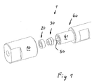
- FIGS. 1 and 2 a hollow fiber terminal 1 with a ring member 20 and a connecting member 30 can be seen, and further a connection part 10 is shown, which can be coupled to one end of a tubular housing part 40 to hold a hollow fiber 50 within the tubular housing part 40 and sealingly position.
- the tubular housing part 40 forms a cartridge, in particular in the manner of an outer tube, in order to store a hollow fiber 50 positioned therein in a sealing manner.
- the connecting part 10 is designed as a kind of sleeve with a through hole and has a radial surface 12 on an inner shoulder, with which it comes into contact with the adjacent end face of the ring element 20 when mounting the hollow fiber connector 1.
- the connecting part 10 may have an internal thread 11, so that it can be screwed onto an external thread 42 of a housing connection 41 corresponding to the outer tube on the tubular housing part 40.
- the ring element 20 is driven in the direction along the fiber longitudinal axis A on the connecting element 30.
- the connecting part 10 overlaps the housing connection 41 and also the connecting element 30 and the ring element 20 to a significant extent. This ensures that the connecting part 10 is aligned essentially coaxially to a fiber longitudinal axis A and axially to the ring element 20 acts.
- this direction of action on the ring element 20 is indicated by axial arrows B, and radially aligned arrows C indicate in which direction a force can act on a first lateral surface 33a of the connecting element 30.
- the cylindrical housing connection 41 of the tubular housing part 40 is shown with two diametrically opposite recesses 43a, 43b formed on its end face and the annular connecting element 30 with two projections 44a, 44b projecting radially outwardly on its peripheral surface and diametrically opposed.
- the projections 44a, 44b form latching noses for engagement in the recesses 43a, 43b on the front side of the housing connection 41, which have a shape complementary to the projections 44a, 44b.
- the recesses 43a, 43b on the housing connection 44 and the projections 44a, 44b on the outside of the connecting element 30 thus together form a lock for a rotationally fixed connection of the connecting element 30 with the housing connection 41.
- the connecting part 10 when the connecting part 10 is screwed onto the housing connection 41, a transmission of the rotational movement via the ring element 20 to the connecting element 30 is prevented ,
- the formation of the recesses 43a, 43b on the housing connection 41 and the projections 44a, 44b on the connecting element 30 is particularly easy by means of injection molding possible, which also also for cost reasons also for the production of the tubular housing part 40, the components required for the hollow fiber connector 1 and thus recommends the entire arrangement or cartridge as a disposable product.
- the hollow fiber 50 By transferring the rotational movement via the connecting element 30 to the hollow fiber 50, the hollow fiber 50 can be twisted in unfavorable cases, whereby damage to the sensitive membrane coating on the hollow fiber 50 can not be ruled out.
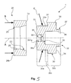
- the Fig. 5 further shows a pressing surface 25 and an inner cone 22 on the ring member 20, and on the connecting member 30, a through hole 350 can be seen, which is defined by a portion 35 and in which a hollow fiber (see. Fig. 3 ) can be kept sealing.
- the connecting element 30 further has a shoulder 32 with a contact surface 31, on which the ring element 20 can strike in the installed position or come to rest, as in FIG Fig. 6 is shown.
- the ring element 20 abuts against the shoulder 32 and overlaps on the side of the connecting element 30, on which in the installed position, the connection part 10 (see. Fig. 3 ) is provided.
- the hollow fiber 50 is held clamped in the passage opening 350 and is thereby compressed somewhat, to a significant extent by a web 351.
- connection part 10 axial connection of the ring element 20 and the connecting element 30 to the tubular housing part 40 can take place via the connection part 10, wherein the force flow directed by the connection part 10 and directed essentially along the fiber longitudinal axis A passes over the ring element 20 and the connecting element 30 is guided into the external thread 42 of the tubular housing part 40, so that a closed line of force between the contact surface 12 and the external thread 42 results:
- the ring element 20 and the connecting element 30 are subjected to pressure, and the connecting part 10 is substantially on Train claimed, in particular in the housing connection 41 overlapping area.
- an axial force can be exerted on the connecting element 30 via the ring element 20, and there is a force flow between the contact surface 12 of the connecting part 10 and the external thread 42 on the housing connection 41, which extends in the axial direction via the ring element 20 and the connecting member 30 flows.
- a large axial force can be transmitted and a secure sealing connection can be produced, in particular also at an interface between the connecting element 30 and the housing connection 41, essentially via a tubular end 37 and / or via a front end face 34 of the connecting element 30, as in FIG Fig. 5 or 6 shown.
- the axial force can be transmitted via the front end face 34.
- both the lateral surface of the tubular end 37 and the front end face 34 or the corresponding contact surfaces on the tubular housing part 40 with a surface over which a sealing effect can be achieved so that a volume 60 between the hollow fiber 50 and the tubular housing part 40 can be sealed from the environment.
- the volume 60 is also formed in part by the connecting element 30, in particular via an inner circumferential surface 36, as in Fig. 3 and 5 shown.
- the lateral surface of the tubular end 37 and the corresponding contact surface on the tubular housing part 40 may be slightly conical, so that can be realized in accordance with the applied axial forces an interference fit.
- a hollow fiber connection 1 despite the possibility of a high axial clamping force, can ensure a gentle and finely adjustable holding and sealing of the hollow fiber 50.
- the function of a radial sealing and holding of the hollow fiber 50 can be separated from the function of an axial sealing of the connecting element 30 with respect to the tubular housing part.
- a first area 30a is provided spatially separated from a second area 30b, and as an intersection between these areas, an intermediate area 30c can be provided which is encompassed by the first area 30a.
- the first region 30a primarily radial pressures are generated and transmitted to the hollow fiber 50, wherein the hollow fiber 50 can be radially restricted to a predetermined extent, as in Fig. 6 shown.
- the hollow fiber is fixed and sealed with its outer lateral surface 51 in the section 35 in the passage opening 350, in particular via a first sealing surface 351a on the web 351 and also via a second sealing surface 35a.
- the radial compressive force is caused by the ring element 20 and passed along a compressed portion 33b, starting from the first lateral surface 33a on the portion 35, in particular on the web 351.
- the ring member 20 can during assembly first via the inner cone 22 with the connecting element 30th be coupled and initially abut on an outer bevel 33 on the connecting element 30.
- an axial force is applied to a rear end face 24a of the ring element 20 via the connection part 10 until the ring element 20 abuts the shoulder 32, ie with a front end face 24 of the ring element 20 on the contact surface 31 is applied. Due to the geometry of the ring element 20 and the position of the shoulder 32, this results in the assembled state of the compressed region 33b, via which a radial force directed onto the portion 35 can be applied.
- the compressed region 33b can be seen on the connecting element 30, via which the ring element 20 both with a part of the inner cone 22 also from a Part of the parallel extending pressing surface 25 acts on the first lateral surface 33 a of the connector 30.
- FIG. 5 shows a preferred embodiment of the hollow fiber connector 1 with the ring member 20 and the connecting member 30, wherein on the ring member 20, the force acts substantially in the direction of the fiber axis A, and on the connecting member 30, the force applied by the ring member 20 also acts somewhat in the direction the fiber longitudinal axis A, but predominantly in the radial direction, ie almost orthogonal to the fiber longitudinal axis A.
- the front end face 24 can be seen, which is intended to be brought into contact with the contact surface 31 of the connector 30.
- High axial forces from the connection part 10 to the housing connection 41 (cf. Fig. 3 ), so that a sealing connection between the connecting element 30 and a housing can be ensured.
- the axial forces are introduced into the ring element 20 via the rear end face 24a, in particular via a contact surface of a connection part.
- the ring element 20 further has the pressing surface 25, which merges into the inner cone 22 and this includes.
- the inner cone 22 is inclined radially outwards, ie it has a small angle in the range of about 5 to 35 or to 40 ° relative to the fiber longitudinal axis A in the direction of the connector 30.
- the inner cone 22 occupies approximately half the width of the ring 20, as shown, and the other half is formed by a surface oriented substantially parallel to the fiber longitudinal axis A or an axis of symmetry of the ring element 20 as part of the pressing surface 25.
- the pressing surface 25 merges via a chamfer 23 in the rear end face 24a.
- the Chamfer 23 can serve, for example, to provide a burr-free edge at the interface to a connection part, so that in the case of a possible relative movement between a connection part and the ring element 20, no high friction
- the connecting element 30 has two regions each with their own function, on the one hand the first region or pressing region 30a and on the other hand the second region 30b.
- the regions 30a, 30b are spatially separated from each other here via the contact surface 31, wherein the pressing region 30a is provided to transmit forces exerted by the ring element 20 on the section 35 on a fiber (not shown).
- the passage 35 delimiting the passage 35 is arranged in the form of a circumferential wall, as shown substantially in the half of the shoulder 32 facing away from half of the pressing portion 30a arranged half, wherein the portion 35 has the web 351, on which a first sealing surface 351 a can essentially take over the sealing and holding function of a fiber.
- a second sealing surface 35a is formed on the portion 35 delimiting the passage opening 350, which, as shown, has larger internal dimensions relative to the web 351.
- the web 351 may exert a greater force or at least a higher pressure on the hollow fiber 50 than the second sealing surface 35a;
- the second sealing surface 35a for example, additionally ensure the function of centering.
- the outer bevel 33 is provided, which may have the same angle to the fiber axis A as the inner cone 22 of the ring, so that a mounting of the ring 20 on the connecting element 30 in a simple manner possible.
- the ring element 20 can be plugged onto the connecting element and positioned there without further support, before it is completely pushed or pressed onto the connecting element 30 via some connecting part.
- the outer bevel 33 is particularly advantageous if an alignment of a connection part with respect to a tubular housing part is to be ensured that the connection part is screwed over a certain distance only to a thread on a housing connection, before it comes into contact with the ring member 20.
- the chamfer 33 and a tilting of the ring member 20 can be prevented, even if the ring member 20 is temporarily no longer accessible before it is postponed.
- the connecting element 30 further has the second lateral surface 38 on the shoulder 32, by means of which a radial twist-securing of the connector 30 in any housing can be ensured.
- This twist-lock z. B. via a particularly rough surface of the second lateral surface 38 in conjunction with a press fit in a housing, but it may also be a positive fit, especially if the shoulder 32 is not cylindrical, but with a toothed or otherwise structured second lateral surface 38.
- the second lateral surface 38 merges via the front end face 34 of the connecting element 30 into the tubular end 37, by means of which the connecting element 30 can be centered in a tubular housing part or a device.
- the inner circumferential surface 36 forms, by virtue of having only slightly smaller internal dimensions than the outer dimensions of the tubular end 37, with the tubular end 37, a rather thin-walled connecting piece compared to other wall thicknesses of the connecting element 30.
- the inner lateral surface 36 passes over an inner bevel transition 39, which is already arranged in the pressing region 30a as shown, into the web 351.
- this inner bevel transition 39 may be due to the design, it may also have a function in that its angle or length has an effect on whether or how much substantially radial forces exerted in the pressing region 30a are transmitted to the second region 30b or not.
- the inner bevel transition 39 is relatively steep, ie greater than 45 ° with respect to the fiber longitudinal axis A executed, and it terminates at a position in the pressing region 30 a, which of the shoulder 32 and the contact surface 31 a has a certain minimum distance, so that here also due to the wall thicknesses and the positions and geometrical conditions, a separation of the pressing portion 30a can be carried by the second portion 30b.
- the area between the inner bevel transition 39 and the shoulder 32 is referred to here as an intermediate region 30c, which has only a low bending stiffness, but a high compressive rigidity.
- the first region 30a can also be regarded as a region which adjoins the intermediate region 30c laterally, ie does not encompass it.
- an intermediate region 30c is provided for the purpose of primarily transmitting bending forces in it and not radial pressure forces.
- the intermediate region 30c is already in the region of the inner circumferential surface 36 and is that portion or part of the first region 30a, which has the lowest wall thickness.
- a pressure exerted on the first lateral surface 33a of the connecting element 30 pressure can be transmitted to the section 35 in a particularly effective manner without deformation in the first region 30a noticeably on the second lateral surface 38 of the second portion 30b transfers. This is then also largely independent of a choice of material for the material or materials of the connecting element 30 possible.
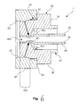
- FIG. 6 shows the components of the FIG. 5 in assembled condition.
- the hollow fiber terminal 1 is now shown in connection with the hollow fiber 50 and it can be seen how a force exerted by the ring element 20 on the connecting element 30 acts on the hollow fiber 50.
- the hollow fiber 50 is held with its outer circumferential surface 51 within the passage opening 350 in the pressing region or section of the connector 30. Due to the inclination or angular position of the inner cone 22 on the ring member 20, in conjunction with the length of the inner cone 22 and the width of the ring 20 of the force action point can be brought into line with the position of the web, in particular depending on the position of the ring 20 on the Connecting element 30. This is indicated by corresponding arrows in the direction of the force effect indicated.
- the hollow fiber 50 is changed both with its outer circumferential surface 51 and with its inner circumferential surface 52 in cross section, compressed in this case.
- the cross-sectional reduction of the hollow fiber 50 is the most significant at the location of the web 351, that is, at the point to which the force vectors are aligned.
- a radial force can be transmitted over the entire area of the through opening 350.
- the ring element 20 rests with its front end face 24 against the contact surface 31 of the shoulder 32. In this way, a force on the connecting element 30 can be homogeneously exerted on the connecting element 30 over a wide region of the pressing region 30a and at the same time be focused on the web depending on the angle of the inner cone 22.
- the web 351 for the cross-sectional constriction of the inner diameter of the sealing surfaces 35a, 351a of the connecting element 30 is arranged at a location of a defined, possibly maximum pressing force.
- This web 351 can seal the fiber 50 by the aforementioned force against a pressure of up to 30 bar.
- slippage of the fiber 50 within the connecting member 30 in the axial direction can be prevented. Due to the evenly applied from the outside force, the fiber 50 is mounted coaxially relative to all other parts of the housing 40 and the cartridge. The precise concentricity of the fiber 50 is of great importance because, as is known, only very poor separation is achieved when the rotational symmetry is poor or absent.
- FIG. 7 shows the hollow fiber terminal 1 in connection with the tubular housing 40 and two connecting parts 10, with the one connection part 10 in the already mounted state and the other connection part 10 in exploded view together with the ring member 20 and the connecting element 30.
- the illustrated housing 40 may be part of a fractionating device, for example.
- the hollow fiber 50 is substantially smaller in diameter than the housing 40, so that there is a volume 60 or radial volume therebetween, in which a transverse flow flows, which is discharged via a collar-shaped connection 70.
- the length of the cartridge 40 can be easily adapted.
- a complete cartridge 40 may include two similar ports on the inlet and outlet sides of the housing port, respectively. If both ports have been closed and thus the hollow fiber is compressed in the respective connecting element 30, the hollow fiber can usually no longer be removed, at least not destructively.
- connection according to the invention for connecting a hollow fiber 50 to a tubular housing part 40 has proven suitable for different fiber diameters.
- a filling of the volume 60 can be done with fine glass or plastic balls, eg with a diameter of about 0.5 mm.
- the cross-flow connection 70 on the cartridge 40 can be designed as a standard connection.
Landscapes
- Physics & Mathematics (AREA)
- Health & Medical Sciences (AREA)
- Life Sciences & Earth Sciences (AREA)
- Chemical & Material Sciences (AREA)
- Analytical Chemistry (AREA)
- Biochemistry (AREA)
- General Health & Medical Sciences (AREA)
- General Physics & Mathematics (AREA)
- Immunology (AREA)
- Pathology (AREA)
- Separation Using Semi-Permeable Membranes (AREA)
- Gasket Seals (AREA)
Applications Claiming Priority (1)
| Application Number | Priority Date | Filing Date | Title |
|---|---|---|---|
| DE102010043877A DE102010043877B3 (de) | 2010-11-12 | 2010-11-12 | Hohlfaseranschluss |
Publications (2)
| Publication Number | Publication Date |
|---|---|
| EP2453231A2 true EP2453231A2 (fr) | 2012-05-16 |
| EP2453231A3 EP2453231A3 (fr) | 2014-02-19 |
Family
ID=45033752
Family Applications (1)
| Application Number | Title | Priority Date | Filing Date |
|---|---|---|---|
| EP11187151.3A Withdrawn EP2453231A3 (fr) | 2010-11-12 | 2011-10-28 | Connexion de fibres creuses |
Country Status (5)
| Country | Link |
|---|---|
| US (1) | US20120119491A1 (fr) |
| EP (1) | EP2453231A3 (fr) |
| JP (1) | JP2012110891A (fr) |
| CN (1) | CN102527235A (fr) |
| DE (1) | DE102010043877B3 (fr) |
Families Citing this family (4)
| Publication number | Priority date | Publication date | Assignee | Title |
|---|---|---|---|---|
| DE102009022368C5 (de) | 2009-05-22 | 2020-12-17 | Dionex Softron Gmbh | Steckereinheit und Verbindungssystem für das Verbinden von Kapillaren, insbesondere für die Hochleistungsflüssigkeitschromatographie |
| EP2852837B1 (fr) | 2012-05-22 | 2023-03-01 | Agilent Technologies, Inc. | Element étanche pour connection fluidique |
| EP3163298B1 (fr) | 2015-10-30 | 2023-12-27 | Dionex Softron GmbH | Raccord de tube capillaire |
| US11274687B2 (en) * | 2016-06-06 | 2022-03-15 | Trajan Scientific Australia Pty Ltd | Liquid junction assembly |
Family Cites Families (6)
| Publication number | Priority date | Publication date | Assignee | Title |
|---|---|---|---|---|
| US2640716A (en) * | 1948-12-28 | 1953-06-02 | Arthur L Bigelow | Tube coupling |
| US6108895A (en) * | 1996-09-09 | 2000-08-29 | The Deutsch Company | Method of axially swaging a male end fitting assembly |
| AU2002216618A1 (en) * | 2000-10-06 | 2002-04-15 | Protasis Corporation | Fluid separation conduit cartridge with encryption capability |
| DE10345817A1 (de) * | 2003-09-30 | 2005-05-25 | Boehringer Ingelheim Microparts Gmbh | Verfahren und Vorrichtung zum Koppeln von Hohlfasern an ein mikrofluidisches Netzwerk |
| US7316777B2 (en) * | 2005-01-28 | 2008-01-08 | Valco Instruments Co., Inc. | Compression fitting nut with interlocked ferrule |
| KR100792683B1 (ko) * | 2006-05-09 | 2008-01-09 | 연세대학교 산학협력단 | 모세관등전집중-중공사흐름장흐름분획법을 이용한 단백질분리장치 및 분리방법 |
-
2010
- 2010-11-12 DE DE102010043877A patent/DE102010043877B3/de not_active Expired - Fee Related
-
2011
- 2011-10-28 EP EP11187151.3A patent/EP2453231A3/fr not_active Withdrawn
- 2011-11-09 US US13/292,331 patent/US20120119491A1/en not_active Abandoned
- 2011-11-11 JP JP2011247520A patent/JP2012110891A/ja active Pending
- 2011-11-14 CN CN201110370485XA patent/CN102527235A/zh active Pending
Non-Patent Citations (1)
| Title |
|---|
| None |
Also Published As
| Publication number | Publication date |
|---|---|
| CN102527235A (zh) | 2012-07-04 |
| US20120119491A1 (en) | 2012-05-17 |
| JP2012110891A (ja) | 2012-06-14 |
| EP2453231A3 (fr) | 2014-02-19 |
| DE102010043877B3 (de) | 2012-03-15 |
Similar Documents
| Publication | Publication Date | Title |
|---|---|---|
| EP2205299B1 (fr) | Seringue à aiguille interchangeable | |
| DE102008059897B4 (de) | Steckereinheit und Verbindungssystem für das Verbinden von Kapillaren, insbesondere für die Hochleistungsflüssigkeitschromatographie | |
| EP1760854B1 (fr) | Traversée de câble | |
| EP1859189B1 (fr) | Raccord a serrage pour un tuyau sanitaire et/ou de chauffage | |
| DE102012110991B4 (de) | Steckereinheit und Verbindungssystem zum Verbinden von Kapillaren, insbesondere für die Hochleistungsflüssigkeitschromatographie | |
| WO2012149930A1 (fr) | Unité de connecteur et système de liaison destiné à relier des capillaires, en particulier pour la chromatographie liquide haute performance | |
| EP2134490A1 (fr) | Porte-outil | |
| DE10048910A1 (de) | Verbindungsstelle | |
| DE3249120C2 (fr) | ||
| DE102007029449A1 (de) | Fliehkraftunterstütztes Werkzeugspannsystem | |
| DE102010043877B3 (de) | Hohlfaseranschluss | |
| EP0565820B1 (fr) | Raccord vissé | |
| DE3013874C2 (de) | Spannsatz in Doppelausführung zur Nabenbefestigung | |
| EP4390207B1 (fr) | Pièce d'accouplement pour un accouplement hydraulique | |
| DE102017102396A1 (de) | Verbindungsstück für die Fluidchromatographie | |
| EP3279615A1 (fr) | Dispositif de mesure de longueur | |
| EP3255330B1 (fr) | Utilisation d'une douille d'etancheite | |
| DE10104508A1 (de) | Schlauch-Verbindung | |
| EP1660262B1 (fr) | Point d'assemblage d'un outil | |
| EP1978290A1 (fr) | Dispositif destiné au raccordement d'une conduite tubulaire, en particulier d'un tuyau flexible, sur un élément de raccordement | |
| EP1412117B1 (fr) | Element d'ecartement pour une pince de serrage et pince de serrage | |
| DE19944247B4 (de) | Anschlußeinrichtung für Fluidleitungen | |
| EP3227041A1 (fr) | Mandrin de serrage | |
| DE102015226536A1 (de) | Kabelverschraubung | |
| WO2004012892A1 (fr) | Dispositif de serrage pour vehicules |
Legal Events
| Date | Code | Title | Description |
|---|---|---|---|
| PUAI | Public reference made under article 153(3) epc to a published international application that has entered the european phase |
Free format text: ORIGINAL CODE: 0009012 |
|
| AK | Designated contracting states |
Kind code of ref document: A2 Designated state(s): AL AT BE BG CH CY CZ DE DK EE ES FI FR GB GR HR HU IE IS IT LI LT LU LV MC MK MT NL NO PL PT RO RS SE SI SK SM TR |
|
| AX | Request for extension of the european patent |
Extension state: BA ME |
|
| PUAL | Search report despatched |
Free format text: ORIGINAL CODE: 0009013 |
|
| AK | Designated contracting states |
Kind code of ref document: A3 Designated state(s): AL AT BE BG CH CY CZ DE DK EE ES FI FR GB GR HR HU IE IS IT LI LT LU LV MC MK MT NL NO PL PT RO RS SE SI SK SM TR |
|
| AX | Request for extension of the european patent |
Extension state: BA ME |
|
| RIC1 | Information provided on ipc code assigned before grant |
Ipc: G01N 30/00 20060101AFI20140116BHEP |
|
| STAA | Information on the status of an ep patent application or granted ep patent |
Free format text: STATUS: THE APPLICATION IS DEEMED TO BE WITHDRAWN |
|
| 18D | Application deemed to be withdrawn |
Effective date: 20140820 |