EP2453254A1 - Vorrichtung zur Überwachung einer Tür mit einem 3-D-Sensor - Google Patents
Vorrichtung zur Überwachung einer Tür mit einem 3-D-Sensor Download PDFInfo
- Publication number
- EP2453254A1 EP2453254A1 EP10014616A EP10014616A EP2453254A1 EP 2453254 A1 EP2453254 A1 EP 2453254A1 EP 10014616 A EP10014616 A EP 10014616A EP 10014616 A EP10014616 A EP 10014616A EP 2453254 A1 EP2453254 A1 EP 2453254A1
- Authority
- EP
- European Patent Office
- Prior art keywords
- mounting
- housing
- sensor
- door
- monitoring
- Prior art date
- Legal status (The legal status is an assumption and is not a legal conclusion. Google has not performed a legal analysis and makes no representation as to the accuracy of the status listed.)
- Granted
Links
- 238000012544 monitoring process Methods 0.000 title claims description 32
- 238000011156 evaluation Methods 0.000 claims abstract description 12
- 238000009434 installation Methods 0.000 claims description 10
- 238000001514 detection method Methods 0.000 claims description 9
- 238000003384 imaging method Methods 0.000 claims description 2
- 238000005259 measurement Methods 0.000 abstract description 7
- 238000000034 method Methods 0.000 abstract description 2
- 230000001419 dependent effect Effects 0.000 description 2
- 239000011159 matrix material Substances 0.000 description 2
- 238000011161 development Methods 0.000 description 1
- 230000018109 developmental process Effects 0.000 description 1
- 230000007613 environmental effect Effects 0.000 description 1
- 231100001261 hazardous Toxicity 0.000 description 1
- 238000005286 illumination Methods 0.000 description 1
- 230000007257 malfunction Effects 0.000 description 1
- 238000012806 monitoring device Methods 0.000 description 1
- 230000003287 optical effect Effects 0.000 description 1
- 230000010363 phase shift Effects 0.000 description 1
- 230000003068 static effect Effects 0.000 description 1
Images





Classifications
-
- G—PHYSICS
- G01—MEASURING; TESTING
- G01S—RADIO DIRECTION-FINDING; RADIO NAVIGATION; DETERMINING DISTANCE OR VELOCITY BY USE OF RADIO WAVES; LOCATING OR PRESENCE-DETECTING BY USE OF THE REFLECTION OR RERADIATION OF RADIO WAVES; ANALOGOUS ARRANGEMENTS USING OTHER WAVES
- G01S7/00—Details of systems according to groups G01S13/00, G01S15/00, G01S17/00
- G01S7/48—Details of systems according to groups G01S13/00, G01S15/00, G01S17/00 of systems according to group G01S17/00
- G01S7/497—Means for monitoring or calibrating
- G01S7/4972—Alignment of sensor
-
- E—FIXED CONSTRUCTIONS
- E05—LOCKS; KEYS; WINDOW OR DOOR FITTINGS; SAFES
- E05F—DEVICES FOR MOVING WINGS INTO OPEN OR CLOSED POSITION; CHECKS FOR WINGS; WING FITTINGS NOT OTHERWISE PROVIDED FOR, CONCERNED WITH THE FUNCTIONING OF THE WING
- E05F15/00—Power-operated mechanisms for wings
- E05F15/40—Safety devices, e.g. detection of obstructions or end positions
- E05F15/42—Detection using safety edges
- E05F15/43—Detection using safety edges responsive to disruption of energy beams, e.g. light or sound
-
- F—MECHANICAL ENGINEERING; LIGHTING; HEATING; WEAPONS; BLASTING
- F16—ENGINEERING ELEMENTS AND UNITS; GENERAL MEASURES FOR PRODUCING AND MAINTAINING EFFECTIVE FUNCTIONING OF MACHINES OR INSTALLATIONS; THERMAL INSULATION IN GENERAL
- F16M—FRAMES, CASINGS OR BEDS OF ENGINES, MACHINES OR APPARATUS, NOT SPECIFIC TO ENGINES, MACHINES OR APPARATUS PROVIDED FOR ELSEWHERE; STANDS; SUPPORTS
- F16M11/00—Stands or trestles as supports for apparatus or articles placed thereon ; Stands for scientific apparatus such as gravitational force meters
- F16M11/02—Heads
- F16M11/04—Means for attachment of apparatus; Means allowing adjustment of the apparatus relatively to the stand
- F16M11/06—Means for attachment of apparatus; Means allowing adjustment of the apparatus relatively to the stand allowing pivoting
-
- F—MECHANICAL ENGINEERING; LIGHTING; HEATING; WEAPONS; BLASTING
- F16—ENGINEERING ELEMENTS AND UNITS; GENERAL MEASURES FOR PRODUCING AND MAINTAINING EFFECTIVE FUNCTIONING OF MACHINES OR INSTALLATIONS; THERMAL INSULATION IN GENERAL
- F16M—FRAMES, CASINGS OR BEDS OF ENGINES, MACHINES OR APPARATUS, NOT SPECIFIC TO ENGINES, MACHINES OR APPARATUS PROVIDED FOR ELSEWHERE; STANDS; SUPPORTS
- F16M13/00—Other supports for positioning apparatus or articles; Means for steadying hand-held apparatus or articles
- F16M13/02—Other supports for positioning apparatus or articles; Means for steadying hand-held apparatus or articles for supporting on, or attaching to, an object, e.g. tree, gate, window-frame, cycle
-
- F—MECHANICAL ENGINEERING; LIGHTING; HEATING; WEAPONS; BLASTING
- F16—ENGINEERING ELEMENTS AND UNITS; GENERAL MEASURES FOR PRODUCING AND MAINTAINING EFFECTIVE FUNCTIONING OF MACHINES OR INSTALLATIONS; THERMAL INSULATION IN GENERAL
- F16P—SAFETY DEVICES IN GENERAL; SAFETY DEVICES FOR PRESSES
- F16P3/00—Safety devices acting in conjunction with the control or operation of a machine; Control arrangements requiring the simultaneous use of two or more parts of the body
- F16P3/12—Safety devices acting in conjunction with the control or operation of a machine; Control arrangements requiring the simultaneous use of two or more parts of the body with means, e.g. feelers, which in case of the presence of a body part of a person in or near the danger zone influence the control or operation of the machine
- F16P3/14—Safety devices acting in conjunction with the control or operation of a machine; Control arrangements requiring the simultaneous use of two or more parts of the body with means, e.g. feelers, which in case of the presence of a body part of a person in or near the danger zone influence the control or operation of the machine the means being photocells or other devices sensitive without mechanical contact
-
- F—MECHANICAL ENGINEERING; LIGHTING; HEATING; WEAPONS; BLASTING
- F16—ENGINEERING ELEMENTS AND UNITS; GENERAL MEASURES FOR PRODUCING AND MAINTAINING EFFECTIVE FUNCTIONING OF MACHINES OR INSTALLATIONS; THERMAL INSULATION IN GENERAL
- F16P—SAFETY DEVICES IN GENERAL; SAFETY DEVICES FOR PRESSES
- F16P3/00—Safety devices acting in conjunction with the control or operation of a machine; Control arrangements requiring the simultaneous use of two or more parts of the body
- F16P3/12—Safety devices acting in conjunction with the control or operation of a machine; Control arrangements requiring the simultaneous use of two or more parts of the body with means, e.g. feelers, which in case of the presence of a body part of a person in or near the danger zone influence the control or operation of the machine
- F16P3/14—Safety devices acting in conjunction with the control or operation of a machine; Control arrangements requiring the simultaneous use of two or more parts of the body with means, e.g. feelers, which in case of the presence of a body part of a person in or near the danger zone influence the control or operation of the machine the means being photocells or other devices sensitive without mechanical contact
- F16P3/141—Safety devices acting in conjunction with the control or operation of a machine; Control arrangements requiring the simultaneous use of two or more parts of the body with means, e.g. feelers, which in case of the presence of a body part of a person in or near the danger zone influence the control or operation of the machine the means being photocells or other devices sensitive without mechanical contact using sound propagation, e.g. sonar
-
- F—MECHANICAL ENGINEERING; LIGHTING; HEATING; WEAPONS; BLASTING
- F16—ENGINEERING ELEMENTS AND UNITS; GENERAL MEASURES FOR PRODUCING AND MAINTAINING EFFECTIVE FUNCTIONING OF MACHINES OR INSTALLATIONS; THERMAL INSULATION IN GENERAL
- F16P—SAFETY DEVICES IN GENERAL; SAFETY DEVICES FOR PRESSES
- F16P3/00—Safety devices acting in conjunction with the control or operation of a machine; Control arrangements requiring the simultaneous use of two or more parts of the body
- F16P3/12—Safety devices acting in conjunction with the control or operation of a machine; Control arrangements requiring the simultaneous use of two or more parts of the body with means, e.g. feelers, which in case of the presence of a body part of a person in or near the danger zone influence the control or operation of the machine
- F16P3/14—Safety devices acting in conjunction with the control or operation of a machine; Control arrangements requiring the simultaneous use of two or more parts of the body with means, e.g. feelers, which in case of the presence of a body part of a person in or near the danger zone influence the control or operation of the machine the means being photocells or other devices sensitive without mechanical contact
- F16P3/142—Safety devices acting in conjunction with the control or operation of a machine; Control arrangements requiring the simultaneous use of two or more parts of the body with means, e.g. feelers, which in case of the presence of a body part of a person in or near the danger zone influence the control or operation of the machine the means being photocells or other devices sensitive without mechanical contact using image capturing devices
-
- F—MECHANICAL ENGINEERING; LIGHTING; HEATING; WEAPONS; BLASTING
- F16—ENGINEERING ELEMENTS AND UNITS; GENERAL MEASURES FOR PRODUCING AND MAINTAINING EFFECTIVE FUNCTIONING OF MACHINES OR INSTALLATIONS; THERMAL INSULATION IN GENERAL
- F16P—SAFETY DEVICES IN GENERAL; SAFETY DEVICES FOR PRESSES
- F16P3/00—Safety devices acting in conjunction with the control or operation of a machine; Control arrangements requiring the simultaneous use of two or more parts of the body
- F16P3/12—Safety devices acting in conjunction with the control or operation of a machine; Control arrangements requiring the simultaneous use of two or more parts of the body with means, e.g. feelers, which in case of the presence of a body part of a person in or near the danger zone influence the control or operation of the machine
- F16P3/14—Safety devices acting in conjunction with the control or operation of a machine; Control arrangements requiring the simultaneous use of two or more parts of the body with means, e.g. feelers, which in case of the presence of a body part of a person in or near the danger zone influence the control or operation of the machine the means being photocells or other devices sensitive without mechanical contact
- F16P3/147—Safety devices acting in conjunction with the control or operation of a machine; Control arrangements requiring the simultaneous use of two or more parts of the body with means, e.g. feelers, which in case of the presence of a body part of a person in or near the danger zone influence the control or operation of the machine the means being photocells or other devices sensitive without mechanical contact using electro-magnetic technology, e.g. tags or radar
-
- G—PHYSICS
- G01—MEASURING; TESTING
- G01B—MEASURING LENGTH, THICKNESS OR SIMILAR LINEAR DIMENSIONS; MEASURING ANGLES; MEASURING AREAS; MEASURING IRREGULARITIES OF SURFACES OR CONTOURS
- G01B21/00—Measuring arrangements or details thereof, where the measuring technique is not covered by the other groups of this subclass, unspecified or not relevant
- G01B21/16—Measuring arrangements or details thereof, where the measuring technique is not covered by the other groups of this subclass, unspecified or not relevant for measuring distance of clearance between spaced objects
-
- G—PHYSICS
- G01—MEASURING; TESTING
- G01C—MEASURING DISTANCES, LEVELS OR BEARINGS; SURVEYING; NAVIGATION; GYROSCOPIC INSTRUMENTS; PHOTOGRAMMETRY OR VIDEOGRAMMETRY
- G01C3/00—Measuring distances in line of sight; Optical rangefinders
-
- G—PHYSICS
- G01—MEASURING; TESTING
- G01S—RADIO DIRECTION-FINDING; RADIO NAVIGATION; DETERMINING DISTANCE OR VELOCITY BY USE OF RADIO WAVES; LOCATING OR PRESENCE-DETECTING BY USE OF THE REFLECTION OR RERADIATION OF RADIO WAVES; ANALOGOUS ARRANGEMENTS USING OTHER WAVES
- G01S17/00—Systems using the reflection or reradiation of electromagnetic waves other than radio waves, e.g. lidar systems
- G01S17/02—Systems using the reflection of electromagnetic waves other than radio waves
- G01S17/04—Systems determining the presence of a target
-
- G—PHYSICS
- G01—MEASURING; TESTING
- G01S—RADIO DIRECTION-FINDING; RADIO NAVIGATION; DETERMINING DISTANCE OR VELOCITY BY USE OF RADIO WAVES; LOCATING OR PRESENCE-DETECTING BY USE OF THE REFLECTION OR RERADIATION OF RADIO WAVES; ANALOGOUS ARRANGEMENTS USING OTHER WAVES
- G01S17/00—Systems using the reflection or reradiation of electromagnetic waves other than radio waves, e.g. lidar systems
- G01S17/88—Lidar systems specially adapted for specific applications
-
- G—PHYSICS
- G01—MEASURING; TESTING
- G01S—RADIO DIRECTION-FINDING; RADIO NAVIGATION; DETERMINING DISTANCE OR VELOCITY BY USE OF RADIO WAVES; LOCATING OR PRESENCE-DETECTING BY USE OF THE REFLECTION OR RERADIATION OF RADIO WAVES; ANALOGOUS ARRANGEMENTS USING OTHER WAVES
- G01S17/00—Systems using the reflection or reradiation of electromagnetic waves other than radio waves, e.g. lidar systems
- G01S17/88—Lidar systems specially adapted for specific applications
- G01S17/89—Lidar systems specially adapted for specific applications for mapping or imaging
-
- G—PHYSICS
- G01—MEASURING; TESTING
- G01S—RADIO DIRECTION-FINDING; RADIO NAVIGATION; DETERMINING DISTANCE OR VELOCITY BY USE OF RADIO WAVES; LOCATING OR PRESENCE-DETECTING BY USE OF THE REFLECTION OR RERADIATION OF RADIO WAVES; ANALOGOUS ARRANGEMENTS USING OTHER WAVES
- G01S7/00—Details of systems according to groups G01S13/00, G01S15/00, G01S17/00
- G01S7/48—Details of systems according to groups G01S13/00, G01S15/00, G01S17/00 of systems according to group G01S17/00
- G01S7/481—Constructional features, e.g. arrangements of optical elements
- G01S7/4811—Constructional features, e.g. arrangements of optical elements common to transmitter and receiver
- G01S7/4813—Housing arrangements
-
- E—FIXED CONSTRUCTIONS
- E05—LOCKS; KEYS; WINDOW OR DOOR FITTINGS; SAFES
- E05F—DEVICES FOR MOVING WINGS INTO OPEN OR CLOSED POSITION; CHECKS FOR WINGS; WING FITTINGS NOT OTHERWISE PROVIDED FOR, CONCERNED WITH THE FUNCTIONING OF THE WING
- E05F15/00—Power-operated mechanisms for wings
- E05F15/70—Power-operated mechanisms for wings with automatic actuation
- E05F15/73—Power-operated mechanisms for wings with automatic actuation responsive to movement or presence of persons or objects
-
- E—FIXED CONSTRUCTIONS
- E05—LOCKS; KEYS; WINDOW OR DOOR FITTINGS; SAFES
- E05Y—INDEXING SCHEME ASSOCIATED WITH SUBCLASSES E05D AND E05F, RELATING TO CONSTRUCTION ELEMENTS, ELECTRIC CONTROL, POWER SUPPLY, POWER SIGNAL OR TRANSMISSION, USER INTERFACES, MOUNTING OR COUPLING, DETAILS, ACCESSORIES, AUXILIARY OPERATIONS NOT OTHERWISE PROVIDED FOR, APPLICATION THEREOF
- E05Y2900/00—Application of doors, windows, wings or fittings thereof
- E05Y2900/10—Application of doors, windows, wings or fittings thereof for buildings or parts thereof
- E05Y2900/13—Type of wing
- E05Y2900/132—Doors
Definitions
- the invention relates to a device for monitoring a door with a 3-D sensor according to the preamble of claim 1.
- Active-infrared sensors are known from the prior art, which are mounted on a door leaf and monitor the area in front of the door level at a few points.
- laser sensors are known which scan the monitoring area by means of beams moved by means of rotational mechanics.
- such sensors are very complex and therefore associated with significant production costs.
- these sensors provide significantly reduced convenience in installation and adjustment to the surveillance area, as a variety of optical components must be adjusted.
- the object of the invention is therefore to provide a device for monitoring a door with a 3-D sensor, which improves the installation and / or installation comfort over the prior art at a reasonable cost.
- the aim of the invention is to develop a universal monitoring sensor for automatic doors (carousel and folding doors).
- the area to be monitored should be easily and quickly adapted to the corresponding application and mounting position.
- the distance of an object in the monitoring field can be determined as a third dimension. This makes it possible not only to monitor a precisely defined area, but to set it to a precisely defined monitoring volume by means of knowledge of the environmental conditions of the sensor.
- the sensor preferably consists of a compact unit, which at the same time includes transmitter and receiver.
- the scene to be monitored by means of z. B. LEDs illuminated. The emitted light is reflected and passes back into the sensor, where it is detected by the receiving unit.
- the receiver consists of a multi-pixel TOF chip.
- Each pixel can receive a measurement beam reflected from an object. For example, modulated IR light is used.
- a phase shift between received signal and emitted signal are evaluated. The corresponding evaluation results in a distance value for each pixel, thereby achieving a three-dimensional / volume acquisition image.
- the optics are designed so that the illumination is concentrated in individual discrete beams, resulting in corresponding spots with a high light intensity.
- the use of a 3-D sensor for monitoring allows more flexibility in the application-specific application.
- the sensor delivers z.
- 2-D sensors it is only possible to say whether there is an object within the considered beam.
- the position of the object is not resolvable.
- a device for monitoring a door with a 3-D sensor which is capable of detecting distances to an object in the monitoring field as a third dimension
- the 3-D sensor is arranged in a housing and wherein immovable in the housing arranged transmitting means for transmitting a measuring beam and receiver means.
- a control unit is provided which is adapted to obtain information about the position of the device, and that an evaluation of the measuring beam takes place by the control unit in response to a position information.
- control unit is designed to be evaluated by the evaluation of the Measuring beam depending on the position information a mounting height of the device after assembly to certain. It is therefore no longer necessary for a calibration of the device to enter a mounting height.
- control unit is further designed to use a height of the installation site as a parameter for a definition of the monitoring field.
- a height of the installation site is a parameter for a definition of the monitoring field.
- position detection means are provided which are designed to automatically detect a position, in particular absolute position with respect to a horizontal of the housing and forward it to a control unit .
- a position detection means for a comprehensive detection of the position of the device can, for. B. an inclination sensor may be provided.
- location information z. B. via input elements such. B. DIP switches are provided to the control unit.
- the device is adapted for mounting in a horizontal base mounting position and for mounting in at least two other different mounting positions relative to the horizontal base mounting position, wherein mounting means for the housing are formed for always identical mounting orientation regardless of the mounting position of the housing, and wherein the mounting means and the Housing are matched to one another such that a clear alignment of the housing is provided on the mounting means in the respective at least two further mounting positions by the mounting means.
- the at least two further mounting positions relate to an arrangement of the device in a corner region of a door to be monitored, wherein the mounting means a tilted attachment of the housing for the corner region with an orientation of the 3-D Allow sensors to the monitoring door only so that a limiting monitoring beam of a surveillance field at least approximately parallel to a door edge of the door to be monitored.
- the mounting means a tilted attachment of the housing for the corner region with an orientation of the 3-D Allow sensors to the monitoring door only so that a limiting monitoring beam of a surveillance field at least approximately parallel to a door edge of the door to be monitored.
- the mounting means comprise a frame which encloses the housing.
- This frame is z. B. configured as a bracket extending over the front of the housing and the side walls of the housing to the mounting means.
- the 3-D sensor in a housing comprises an acceptor field and / or a sensor field.
- a receiver field many measure beams can be evaluated in particular simultaneously, with a transmitter field having a comparatively large area, in particular with several measuring beams, is scannable.
- a transmitter matrix and a receiver matrix are used.
- the 3-D senosor is an imaging sensor in which an object point is imaged on an associated sensor point.
- FIG. 1a a representation of a housing 1 for a device according to the invention for monitoring a
- the housing 1 is at least partially surrounded by a mounting frame 2, which engages on the back of the housing 1 in a mounting plate 3. In this way, the housing 1 is held on the mounting means formed by the mounting frame 2 and the mounting plate 3.
- FIG. 1b shows an exploded view of the components housing 1, mounting frame 2 and mounting plate. 3
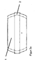
- FIG. 2a shows a frontal view of the arrangement according to FIG. 1a ,
- the housing 1 has on its right and left outer sides a shape corresponding to a circle segment, wherein the radius is modeled by the mounting frame, in particular coordinated on the inside thereof.
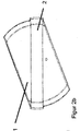
- FIG. 2b shows a first pivoted position of the housing 1 in the mounting frame 2, wherein the underside of the housing, on which the signals required to monitor a door are emitted, in this case shown pivoted to the right.
- the mounting frame 2 holds the housing 1 at the radius of the left and right side wall, so that the housing 1 is held by the mounting frame 2 with the mounting plate 3 (not shown here) as a mounting means.
- Figure 2c shows a correspondingly pivoted to the left arrangement of the device according to the invention for monitoring a door.
- FIG. 3a shows a representation of the mounting means, consisting of mounting frame 2 and mounting plate 3 without housing disposed therein.
- the mounting means are preassembled by attaching the mounting plate 3 to a door, after which the housing 1 is inserted with the 3D sensor contained therein in the mounting means.
- the mounting plate is for an always same mounting position, eg. B. horizontal position provided.
- FIG. 3b shows an exploded view of the mounting means formed from mounting frame 2 and mounting plate 3.
- the Mounting frame 2 in this case has at its the mounting plate 3 facing ends latching hooks 2a, which engage positively in corresponding receptacles 3a on the mounting plate 3.
- the mounting plate 3 further has two mounting elongated holes 3b, which allow the installer a simple and precise installation on a door leaf.
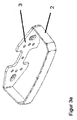
- FIG. 4 shows an exploded view of a arranged in a mounting frame housing 1.
- the housing 1 in this case has on its rear side a plurality of pins according to the invention.
- the existing center pin 4 is arranged centrally in the radius of the housing 1, so that the housing 1 according to the FIGS. 2b and 2c is rotatably mounted about the center pin 4.
- two side journals 5 are arranged on the left and on the right of the center pin 4, which can preferably have latching clamping means.
- the illustrated mounting plate 3 has in its center a central bore 6 for receiving the center pin 4.
- the side journals 5 can be introduced into corresponding positional holes, the positional holes are always arranged diagonally opposite rotationally symmetrical about the central bore 6.
- the first position holes 7a represent the horizontal plane mounting position.
- the second position holes 7b correspond to those in FIG FIG. 2b shown pivoting of the beam path to the right
- the third position holes 7c correspond to the illustration Figure 2c .
- FIG. 5 shows a representation of a housing 1 with therein contained 3D sensor, wherein on the front of the housing 1 controls, for example in the form of potentiometers or the like are provided.
- the controls are in one Operating elements area 8 arranged, which is arranged easily accessible on the front of the housing for the installer.
- the installer can make adjustments, for example, to the mounting position, and / or adjust the detection field of the device for monitoring a door by means of appropriate adjustment parameters.
- the mounting frame 2 is arranged around the housing 1, it covers the central area 8 with the access points to the operating elements, wherein the cover can additionally constitute a seal in all mounting positions.
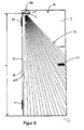
- FIG. 6 shows an example of an arrangement of a 3D sensor according to the invention as a device for monitoring a door, in this case a hinged door hinged side 16.
- the housing 1 is in this case arranged with the mounting frame 2 in a left upper corner portion 17 of the door 16.
- the door leaf 9 is hereby struck on the left side by fittings 10 and has a doorknob 11 on the right side.
- the device for monitoring a door is aligned so that it corresponds as shown in FIG FIG. 2b has a detection beam 12 pivoted to the right with an outer measuring beam 15a.
- the beam path is aligned on the left, the fittings 10 side facing such that a measuring beam 15b almost perpendicular to the ground, so almost parallel along a door leaf edge 14 of a door leaf page 13 extends.
- the housing 1 is on the door 16, z. B. mounted at a height h.
- Corresponding arrangements are both centric, as well as on the right upper side, with differently hinged doors, conceivable. Centric arrangements may be useful in double wing doors. Gegebebebfalls we the housing not on the door, but attached to the Monramen or the wall.
- the height of the door is in this case with reference to a defined mounting position of the mounting means 2, 3 indicate, this being easy to accomplish, for example, by presenting a Montageschabione for the door edge by the installer.
- a position sensor is provided which the orientation according to FIGS. 2a . 2 B and 2c detected.
- bearing sensors As an alternative to the bearing sensors, corresponding sensors are also conceivable which, for example via push buttons, monitor the side pegs and / or the positional bores 7a to 7b in order to determine an orientation of the device monitoring of a door therefrom.
Landscapes
- Engineering & Computer Science (AREA)
- Physics & Mathematics (AREA)
- General Engineering & Computer Science (AREA)
- Radar, Positioning & Navigation (AREA)
- Remote Sensing (AREA)
- General Physics & Mathematics (AREA)
- Mechanical Engineering (AREA)
- Computer Networks & Wireless Communication (AREA)
- Electromagnetism (AREA)
- Geophysics And Detection Of Objects (AREA)
- Power-Operated Mechanisms For Wings (AREA)
- Burglar Alarm Systems (AREA)
- Length Measuring Devices By Optical Means (AREA)
Abstract
Description
- Die Erfindung betrifft eine Vorrichtung zur Überwachung einer Tür mit einem 3-D-Sensor nach dem Oberbegriff des Anspruchs 1.
- Automatische Flügel und Karusselltüren können für Benutzer gefährlich werden, falls deren Gefahrenbereiche vor dem Türblatt nicht überwacht sind. Da sich die gefahrbringenden Komponenten während des Öffnungs- und Schließprozesses bewegen, bewegt sich auch das zu überwachende Gefahrenfeld mit. Des Weiteren muss sich das zu überwachende Feld in der Größe während der Bewegung ggf. verändern. Dadurch entsteht das Bedürfnis, den Überwachungssensor mit der gefahrbringenden Komponente mit zu bewegen, wobei eine Anpassung an die breite Vielfalt von unterschiedlichen Türgrößen und benötigten Überwachungsfeldern erwünscht ist. Wirtschaftliche Faktoren verlangen weiterhin, dass ein universeller Sensor mit einfach anzupassenden Überwachungseigenschaften bereitgestellt wird.
- Aufgrund der gegebenen Anforderungen sucht die Branche nach Sensorlösungen mit flexiblen Auswertemöglichkeiten, welche beispielsweise eine Auswertung der dritten Dimension, welche die Distanz des überwachten Objekts vom Sensor betrifft, realisiert werden. Derartige Sensoren können auch zur statischen Montage für Überwachungsanwendungen bestimmter Überwachungsfelder eingesetzt werden.
- Aus dem Stand der Technik sind aktiv-infrarot Sensoren bekannt, welche an einem Türblatt montiert werden und den Bereich vor der Türebene an wenigen Punkten überwachen. Alternativ hierzu sind Lasersensoren bekannt, welche mittels über Rotationsmechaniken bewegten Strahlen den Überwachungsbereich abscannen. Derartige Sensoren sind jedoch sehr komplex und daher mit erheblichen Herstellungskosten verbunden. Außerdem bieten diese Sensoren einen wesentlich eingeschränkten Komfort bei der Installation und Anpassung an den überwachungsbereich, da eine Vielzahl von optischen Komponenten justiert werden müssen.
- Aufgabe der Erfindung ist es daher, eine Vorrichtung zur Überwachung einer Tür mit einem 3-D-Sensor bereitzustellen, welche bei vertretbaren Kosten den Montage- und/oder Installationskomfort gegenüber dem Stand der Technik verbessert.
- Ausgehend vom Oberbegriff des Anspruchs 1 wird diese Erfindung durch die kennzeichnenden Merkmale des Anspruchs 1 gelöst. Vorteilhafte Weiterbildungen sowie zweckmäßige Ausgestaltungen sind den abhängigen Ansprüchen gekennzeichnet.
- Ziel der Erfindung ist es, einen universellen Überwachungssensor für automatische Türen (Karussell- und Flügeltüren) zu entwickeln. Der zu überwachende Bereich soll dabei einfach und schnell der entsprechenden Applikation und Montageposition angepasst werden. Durch die Verwendung des TOF-Prinzips (Time-of-Flight) kann die Distanz eines Objekts im Überwachungsfeld als dritte Dimension bestimmt werden. Dadurch ist es möglich, nicht nur eine genau definierte Fläche zu überwachen, sondern mittels Kenntnis der Umgebungsbedingungen des Sensors diesen auf ein genau definiertes Überwachungsvolumen einzustellen. Der Sensor besteht dabei vorzugsweise aus einer kompakten Einheit, welche zugleich Sender und Empfänger beinhaltet. Im ersten Schritt wird die zu überwachende Szenerie mittels z. B. LEDs beleuchtet. Das ausgesendete Licht wird reflektiert und gelangt zurück in den Sensor, wo es mittels der Empfangseinheit detektiert wird. Der Empfangsteil besteht aus einem TOF-Chip mit mehreren Pixel. Jeder Pixel kann einen von einem Objekt reflektierten Messstrahl empfangen. Zum Beispiel wird moduliertes IR-Licht eingesetzt. Zur Abstandsbestimmung kann eine Phasenverschiebung zwischen empfangenem Signal und ausgesandtem Signal ausgewertet werden. Durch die entsprechende Auswertung resultiert ein Distanzwert für jedes Pixel, wodurch ein dreidimensionales/volumenmäßiges Erfassungsbild erzielt wird. Die Optik ist so ausgelegt, dass die Beleuchtung in einzelne diskrete Strahlen gebündelt bleibt, was zu entsprechenden Spots mit einer hohen Lichtintensität führt.
- Die Verwendung eines 3-D-Sensors für die Überwachung ermöglicht mehr Flexibilität bei der applikationsspezifischen Anwendung. Der Sensor liefert z. B. ortsabhängig (in der x-y-Ebene bzw. der Ebene senkrecht zur Sensorachse) die Distanzwerte zum Objekt. Bei 2-D-Sensoren ist lediglich die Aussage möglich, ob sich innerhalb des betrachteten Strahles ein Objekt befindet. Die Position des Objekts ist nicht auflösbar. Beim TOF-Prinzip kann man aber auch die Distanz zur Auswertung verwenden, wodurch sich neue Möglichkeiten bei der intelligenten Auswertung dieser Signale ergeben.
- Bei einer Vorrichtung zur Überwachung einer Tür mit einem 3-D-Sensor, der in der Lage ist, Distanzen zu einem Objekt im Überwachungsfeld als dritte Dimension zu erfassen, wobei der 3-D-Sensor in einem Gehäuse angeordnet ist und wobei im Gehäuse unbeweglich angeordnete Sendemittel zum Senden eines Messstrahls und Empfängermittel.zum Empfangen des reflektierten Messstrahls vorgesehen sind, liegt ein Aspekt der Erfindung darin, dass eine Steuereinheit vorgesehen ist, die dazu ausgelegt ist, Informationen über die Lage der Vorrichtung zu erhalten, und dass eine Auswertung des Messstrahls durch die Steuereinheit in Abhängigkeit einer Lageinformation stattfindet. Dadurch lässt sich die Montage einer Überwachungsvorrichtung vereinfachen und zuverlässiger gestalten. Denn mit einer Lageinformation kann die Vorrichtung nach einer Montage erfasste Messstrahlen eindeutig der Umgebung zuordnen und somit auch richtig auswerten. Darüber hinaus ist.es möglich, dass sich nach der Montage die Vorrichtung sozusagen selber justiert. Zum Beispiel ist die Steuereinheit dazu ausgelegt, durch die Auswertung des Messstrahls in Abhängigkeit der Lageinformation eine Montagehöhe der Vorrichtung nach einer Montage zu bestimmten. Es ist damit nicht mehr erforderlich für eine Kalibrierung der Vorrichtung eine Montagehöhe einzugeben.
- In einer bevorzugten Ausgestaltung der Erfindung ist die Steuereinheit weiter dazu ausgelegt, eine Höhe des Montageortes als Parameter für eine Definition des überwachungsfeldes einzusetzen. Um eine vollständige Definition des Überwach-angsfeldes vornehmen zu können, ist es bei üblichen Flügeltüren dann lediglich noch notwendig die Breite des Überwachungsfeldes anzugeben. Damit lassen sich Montage- und Eingabefehler minimieren.
- Um auch eine Automatisierung einer Lageermittlung und Weiterleitung an die Steuereinheit zu ermöglichen, wird im Weiteren vorgeschlagen, das Lageerkennungsmittel vorhanden sind, die derart ausgebildet sind, eine Lage, insbesondere absolute Lage in Bezug auf eine Horizontale des Gehäuses automatisch zu erfassen und an eine Steuereinheit weiterzuleiten. Für eine umfassende Erfassung der Lage der Vorrichtung kann z. B. ein Neigungssensor vorgesehen sein. Denkbar ist auch, dass Lageinformationen z. B. über Eingabeelemente, wie z. B. DIP-Switches der Steuereinheit zur Verfügung gestellt werden.
- Außerdem möglich ist die Erfassung einer Position zu einer vormontierten Grundplatte in automatischer Form, z. B. über Sensormittel, wie Schaltelemente.
- Denkbar ist jedoch auch eine möglichst fehlerfreie Montage über geeignet ausgebildete Montagemittel zu erreichen. Zum Beispiel ist die Vorrichtung für eine Anbringung in einer horizontalen Grundmontageposition und für die Anbringung in wenigstens zwei weiteren unterschiedlichen Montagepositionen bezogen auf die horizontale Grundmontageposition ausgelegt, wobei Montagemittel für das Gehäuse für eine immer gleiche Montageausrichtung unabhängig von der Montageposition des Gehäuses ausgebildet sind, und wobei die Montagemittel und das Gehäuse derart aufeinander abgestimmt sind, dass eine eindeutige Ausrichtung des Gehäuses an den Montagemitteln in den jeweils wenigstens zwei weiteren Montagepositionen durch die Montagemittel vorgesehen ist.
- Eine Vorgabe einer Grundposition und mindestens zwei weiteren Montagepositionen, welche als definierte Positionen vorliegen, vereinfachen einem Installateur die Montage und Ausrichtung eines entsprechenden 3-D-Seneor5 erheblich, wodurch Positionierungsfehler und dadurch resultierende Fehlfunktionen vermieden werden.
- Um eine Montage noch zuverlässiger zu gestalten, wird überdies vorgeschlagen, dass die wenigstens zwei weiteren Montagepositionen eine Anordnung der Vorrichtung in einem Eckbereich einer zu überwachenden Tür betreffen, wobei die Montagemittel eine verkippte Anbringung des Gehäuses für den Eckbereich mit einer Ausrichtung des 3-D-Sensors zur überwachenden Tür nur so zulassen, dass ein begrenzender überwachungsstrahl eines überwachungsfeldes zumindest annähernd parallel zu einer Türkante der zu überwachenden Tür verläuft. Es sind in diesem Zusammenhang nur drei Montagepositionen des Gehäuses zugelassen. Damit lassen sich Montagefehler bei einer richtigen, immer gleichen Montage mit Montagemittel für die drei Positionen ausschließen.
- Zur Realisierung einer einfachen Anbringung des Gehäuses der Vorrichtung an den Montagemitteln ist es im Weiteren bevorzugt, wenn die Montagemittel einen Rahmen umfassen, der das Gehäuse umschließt. Dieser Rahmen ist z. B. als Bügel ausgestaltet, der über die Front des Gehäuses und die Seitenwände des Gehäuses zu den Montagemitteln verläuft.
- Um eine hohe Auflösung des 3-D-Sensors zu erreichen, wird darüber hinaus vorgeschlagen, dass der 3-D-Sensor in einem Gehäuses ein Enpfängerfeld und/oder ein Sensorfeld umfasst. Mit einem Empfängerfeld lassen sich viele Measstrahlen insbesondere gleichzeitig auswerten, wobei mit einem Senderfeld eine vergleichsweise große Fläche, insbesondere mit mehreren Messstrahlen, abtastbar ist.
- Insbesondere wird eine Sendermatrix und eine Empfängermatrix eingesetzt.
- Um eine zuverlässige Objektdetektion und Auswertung zu realisieren, ist es darüber hinaus bevorzug, wenn der 3-D-Senosor ein bildgebender Sensor ist, bei welchem ein Objektpunkt auf einem zugeordneten Sensorpunkt abgebildet wird.
- Im Rahmen des Ausführungsbeispiels zeigen
-
Figur 1a ein montierter 3-D-Sensor in der Grundmontageposition; -
Figur 1b Explosionsdarstellung des Sensorgehäuses und der Vorrichtung für eine Anbringung des Sensors; -
Figur 2a Frontansicht der Grundmontageposition nachFigur 1a ; -
Figur 2b erste weitere Montageposition; -
Figur 2c zweite weitere Montageposition; -
Figur 3a Vorrichtung zur Anbringung im geschlossenen Zustand; -
Figur 3b Vorrichtung zur Anbringung im geöffneten Zustand; -
Figur 4 rückseitige Darstellung der Vorrichtung zur Anbringung sowie des 3-D-Sensors; -
Figur 5 Frontansicht des 3-D-Sensors ohne Anbringungsvorrichtung; -
Figur 6 exemplarische Darstellung einer Montageposition. - Im Einzelnen zeigt
Figur 1a eine Darstellung eines Gehäuses 1 für eine erfindungsgemäße Vorrichtung zur Überwachung einer - Tür. Das Gehäuse 1 ist zumindest teilweise von einem Montagerahmen 2 umgeben, welcher an der Rückseite des Gehäuses 1 in eine Montageplatte 3 eingreift. Auf diese Weise wird das Gehäuse 1 an den Montagemitteln, gebildet durch den Montagerahmen 2 und die Montageplatte 3, gehalten.
-
Figur 1b zeigt eine Explosionsdarstellung der Bestandteile Gehäuse 1, Montagerahmen 2 sowie Montageplatte 3. -
Figur 2a zeigt eine Frontalansicht der Anordnung nachFigur 1a . Das Gehäuse 1 weist an seiner rechten und linken Außenseite eine einem Kreissegment entsprechende Formgebung auf, wobei der Radius durch den Montagerahmen, insbesondere auf dessen Innenseite abgestimmt nachempfunden wird. -
Figur 2b zeigt eine erste verschwenkte Position des Gehäuses 1 im Montagerahmen 2, wobei die Unterseite des Gehäuses, an welcher die zur Überwachung einer Tür benötigten Signale ausgesandt werden, vorliegend nach rechts verschwenkt dargestellt ist. Der Montagerahmen 2 fasst das Gehäuse 1 am Radius der linken bzw. rechten Seitenwand, so dass das Gehäuse 1 durch den Montagerahmen 2 mit der Montageplatte 3 (hier nicht dargestellt) als Montagemittel gehalten wird. -
Figur 2c zeigt eine entsprechend nach links verschwenkte Anordnung der erfindungsgemäßen Vorrichtung zur Überwachung einer Tür. -
Figur 3a zeigt eine Darstellung der Montagemittel, bestehend aus Montagerahmen 2 und Montageplatte 3 ohne darin angeordnetes Gehäuse. Die Montagemittel werden durch Anbringung der Montageplatte 3 an einer Tür vormontiert, wonach das Gehäuse 1 mit dem darin enthaltenen 3D-Sensor in die Montagemittel eingebracht wird. Die Montageplatte ist für eine immer gleiche Montageposition, z. B. horizontale Position, vorgesehen. -
Figur 3b zeigt eine Explosionsdarstellung der Montagemittel gebildet aus Montagerahmen 2 und Montageplatte 3. Der Montagerahmen 2 weist hierbei an seinen der Montageplatte 3 zugewandten Enden Rasthaken 2a auf, welche in entsprechende Aufnahmen 3a an der Montageplatte 3 formschlüssig eingreifen. Die Montageplatte 3 verfügt des Weiteren über zwei Montagelanglöcher 3b, welche dem Installateur eine einfache und präzise Montage an einem Türblatt ermöglichen. -
Figur 4 zeigt eine Explosionsdarstellung eines in einem Montagerahmen angeordneten Gehäuses 1. Das Gehäuse 1 weist hierbei auf seiner Rückseite eine Mehrzahl von erfindungsgemäßen Zapfen auf. Der vorhandene Mittelzapfen 4 ist dabei zentrisch im Radius des Gehäuses 1 angeordnet, so dass das Gehäuse 1 entsprechend derFiguren 2b und2c um den Mittelzapfen 4 drehbar gelagert ist. Entlang einer horizontalen Richtung des Gehäuses 1 sind links sowie rechts vom Mittelzapfen 4 zwei Seitenzapfen 5 angeordnet, welche vorzugsweise über einrastende Spannmittel verfügen können. - Die dargestellte Montageplatte 3 weist in ihrem Zentrum eine zentrische Bohrung 6 für die Aufnahme des Mittelzapfens 4 auf.
- Entsprechend den in
Figur 2a bis 2c dargestellten Montagepositionen können die Seitenzapfen 5 in entsprechende Lagebohrungen eingebracht werden, wobei die Lagebohrungen stets diagonal gegenüberliegend rotationssymmetrisch um die zentrische Bohrung 6 angeordnet sind. So stellen die ersten Lagebohrungen 7a die horizontal ebene Montageposition dar. Die zweiten Lagebohrungen 7b entsprechen der inFigur 2b dargestellten Verschwenkung des Strahlengangs nach rechts, die dritten Lagebohrungen 7c entsprechen der Darstellung nachFigur 2c . Auf diese Weise steht dem Installateur ein einfaches vorgegebenes Raster zur Verfügung, welches die Montage der Vorrichtung zur Überwachung einer Tür erheblich vereinfacht, ohne dabei Nachteile in Bezug auf die Montagepräzision in Kauf zu nehmen. -
Figur 5 zeigt eine Darstellung eines Gehäuses 1 mit darin enthaltenem 3D-Sensor, wobei an der Vorderseite des Gehäuses 1 Bedienelemente, beispielsweise in Form von Potentiometern oder ähnlichem vorgesehen sind. Die Bedienelemente sind in einem Bedienelemente-Bereich 8 angeordnet, welcher an der Vorderseite des Gehäuses für den Installateur gut zugänglich angeordnet ist. Der Installateur kann Anpassungen, beispielsweise an die Montageposition vornehmen, und/oder durch entsprechende Justierparameter das Erfassungsfeld der Vorrichtung zur Überwachung einer Tür einstellen. Sobald der Montagerahmen 2 um das Gehäuse 1 angeordnet wird, deckt dieser den zentrischen Bereich 8 mit den Zugängen zu den Bedienelementen ab, wobei die Abdeckung in allen Montagepositionen zusätzlich eine Abdichtung darstellen kann. -
Figur 6 zeigt exemplarisch eine Anordnung eines erfindungsgemäßen 3D-Sensors als Vorrichtung zur Überwachung einer Tür, vorliegend einer einseitig angeschlagenen Flügeltüre 16. Das Gehäuse 1 ist hierbei mit dem Montagerahmen 2 in einem linken oberen Eckebereich 17 der Tür 16 angeordnet. Das Türblatt 9 ist hierbei linksseitig durch Beschläge 10 angeschlagen und weist rechtsseitig eine Türklinke 11 auf. Die Vorrichtung zur Überwachung einer Tür ist so ausgerichtet, dass sie entsprechend der Darstellung inFigur 2b einen nach rechts verschwenkten Erfassungsstrahlengang 12 mit einem äußeren Messstrahl 15a aufweist. Der Strahlengang ist auf der linken, den Beschlägen 10 zugewandten Seite derart ausgerichtet, dass ein Messstrahl 15b nahezu senkrecht zum Boden, also nahezu parallel entlang einer Türblattkante 14 einer Türblattseite 13 verläuft. Beim Verschwenken des Türblatts 9 wird somit keine Detektion von Wandelementen erfolgen, an welchen die Beschläge 10 angeordnet sind. - Das Gehäuse 1 ist an der Tür 16, z. B. in einer Höhe h montiert. Entsprechende Anordnungen sind sowohl zentrisch, als auch an der rechten oberen Seite, bei anders angeschlagenen Türen, denkbar. Zentrische Anordnungen können bei Doppelflügeltüren zweckmäßig sein. Gegebebebfalls wir das Gehäuse nicht an der Tür, sondern am Türramen oder der Wand befestigt.
- Über die senkrechten Strahlen an der Türblattseite 13 lässt sich unter anderem auch die Höhe der Tür bestimmen, in dem die Abstandsmessung bis zum reflektierenden Untergrund erfolgt. Die Höhe der Tür ist hierbei unter Bezug einer definierten Montageposition der Montagemittel 2, 3 anzugeben, wobei dies beispielsweise durch Vorlage einer Montageschabione für die Türkante leicht durch den Installateur zu bewerkstelligen ist.
- Zum Beispiel ist in der Vorrichtung ein Lagesensor vorgesehen, welcher die Orientierung entsprechend der
Figuren 2a ,2b und2c erfasst. - Alternativ zu den Lagersensoren sind auch entsprechende Sensoren denkbar, welche, beispielsweise über Drucktaster, die Seitenzapfen und/oder die Lagebohrungen 7a bis 7b überwachen, um daraus eine Orientierung der Vorrichtungsüberwachung einer Tür zu ermitteln.
- Durch entsprechend angepasste Auswertebestandteile lassen sich auf diese Weise exakte Positionierungen einzelner Objekte im Gefahrenbereich der Tür ermitteln, ohne dass aufwendige hochpräzise Montageschritte bei der Anordnung der erfindungsgemäßen Vorrichtung vorgenommen werden müssen.
-
- 1
- Gehäuse
- 2
- Montagerahmen
- 2a
- Rasthaken
- 3
- Montageplatte
- 3a
- Aufnahmen
- 3b
- Montagelanglöcher
- 4
- Mittelzapfen
- 5
- Seitenzapfen
- 6
- zentrische Bohrung
- 7a
- erste Lagebohrungen
- 7b
- zweite Lagebohrungen
- 7c
- dritte Lagebohrungen
- 8
- Bedienelemente-Bereich
- 9
- Türblatt
- 10
- Beschlag
- 11
- Klinke Erfassungsstrahlengang
- 13
- Türblattseite
- 14
- Türblattkante
- 15a
- Messstrahl
- 15b
- Messstrahl
- 16
- Flügeltüre
- 17
- Eckbereich
Claims (10)
- Vorrichtung zur Überwachung einer Tür mit einem 3-D-Sensor, der in der Lage ist, Distanzen zu einem Objekt im tlberwachungsfeld als dritte Dimension zu erfassen, wobei der 3-D-Sensor in einem Gehäuse (1) angeordnet ist und wobei im Gehäuse (1) unbeweglich angeordnetes Sendemittel zum Senden eines Messstrahls und Empfängermittel zum Empfangen eines reflektierten Messstrahls vorgesehen sind, dadurch gekennzeichnet, dass eine Steuereinheit vorgesehen ist, die dazu ausgelegt ist, eine Information über die Lage der Vorrichtung zu erhalten, und dass eine Auswertung des Messstrahls durch die Steuereinheit in Abhängigkeit einer Lageinformation stattfindet.
- Vorrichtung nach Anspruch 1, dadurch gekennzeichnet, dass die Steuereinheit dazu ausgelegt ist, durch Auswertung des Messstrahls in Abhängigkeit der Lageinformation eine Montagehöhe (h) der Vorrichtung nach einer Montage zu bestimmen.
- Vorrichtung nach einem der vorhergehenden Ansprüche, dadurch gekennzeichnet, dass die Steuereinheit dazu ausgelegt ist, eine Höhe (h) des Montageortes als Parameter für die Definition eines Überwachungsfeldes einzusetzten.
- Vorrichtung nach einem der vorhergehenden Ansprüche, dadurch gekennzeichnet, dass Lageerkennungsmittel vorhanden sind, die dazu ausgebildet sind, eine Lage, insbesondere absolute Lage in Bezug auf eine Horizontale des Gehäuses, automatisch zu erfassen und an eine Steuereinheit weiterzuleiten.
- Vorrichtung nach dem Oberbegriff des Anspruchs 1, insbesondere nach einem der vorhergehenden Ansprüche, dadurch gekennzeichnet, dass die Vorrichtung für eine Anbringung in einer horizontalen Grundmontageposition und für die Anbringung in wenigstens zwei weiteren unterschiedlichen Montagepostionen bezogen auf die horizontale Grundmontageposition ausgelegt ist, wobei Montagemittel (2,3) für das Gehäuse (1) für eine immer gleiche Montageausrichtung unabhängig von der Montageposition des Gehäuses (1) ausgebildet sind und wobei-die Montagemittel (2,3) und das Gehäuse (1) derart aufeinander abgestimmt sind, dass eine eindeutige Ausrichtung des Gehäuses (1) an den Montagemitteln (2,3) in den jeweils wenigstens zwei weiteren Montagepositionen durch die Montagemittel (2,3) gewährleistet ist.
- Vorrichtung nach dem Oberbegriff des Anspruchs 1, insbesondere nach einem,der vorhergehenden Ansprüche, dadurch gekennzeichnet, dass die wenigstens zwei weiteren Montagepositionen eine Anordnung der Vorrichtung in einem Eckbereich einer zur überwachenden Tür (16) betreffen, wobei die Montagemittel (2,3) eine verkippte Anbringung des Gehäuses (1) für einen Eckbereich (17) mit einer Ausrichtung des 3-D-Sensors zur überwachenden Tür (16) nur so zulassen, dass ein begrenzender Überwachur.gsstrahl (15b) eines Cberwachungsfeldes (12) zumindest annähernd parallel zu einer Türkante (14) der zu überwachenden Tür (16) verläuft.
- Vorrichtung nach einem der vorhergehenden Ansprüche, dadurch gekennzeichnet, dass die Montagemittel (2,3) nur genau drei Montagepositionen des Gehäuses (1) zulassen.
- Vorrichtung nach einem der vorhergehenden Ansprüche, dadurch gekennzeichnet, dass die Montagemittel (2,3) einen Rahmen (2) umfassen, der das Gehäuse umschließt.
- Vorrichtung nach einem der vorhergehenden Ansprüche, dadurch gekennzeichnet, dass der 3-D-Sensor in einem Gehäuse (1) ein Empfängerfeld und/oder ein Senderfeld umfasst.
- Vorrichtung nach einem der vorgenannten Ansprüche, dadurch gekennzeichnet, dass der 3-D-Sensor ein bildgebender Sensor ist, bei welchem ein Objektpunkt auf einem zugeordneten Sensorpunkt abgebildet wird.
Priority Applications (4)
| Application Number | Priority Date | Filing Date | Title |
|---|---|---|---|
| DK10014616.6T DK2453254T3 (da) | 2010-11-15 | 2010-11-15 | Indretning til overvågning af en dør med en 3D-sensor |
| EP10014616A EP2453254B1 (de) | 2010-11-15 | 2010-11-15 | Vorrichtung zur Überwachung einer Tür mit einem 3-D-Sensor |
| US13/295,624 US8868376B2 (en) | 2010-11-15 | 2011-11-14 | Apparatus for monitoring a door with a 3D sensor |
| CN201110445586.9A CN102608614B (zh) | 2010-11-15 | 2011-11-15 | 用3d传感器监测门的设备 |
Applications Claiming Priority (1)
| Application Number | Priority Date | Filing Date | Title |
|---|---|---|---|
| EP10014616A EP2453254B1 (de) | 2010-11-15 | 2010-11-15 | Vorrichtung zur Überwachung einer Tür mit einem 3-D-Sensor |
Publications (2)
| Publication Number | Publication Date |
|---|---|
| EP2453254A1 true EP2453254A1 (de) | 2012-05-16 |
| EP2453254B1 EP2453254B1 (de) | 2013-01-16 |
Family
ID=43858374
Family Applications (1)
| Application Number | Title | Priority Date | Filing Date |
|---|---|---|---|
| EP10014616A Active EP2453254B1 (de) | 2010-11-15 | 2010-11-15 | Vorrichtung zur Überwachung einer Tür mit einem 3-D-Sensor |
Country Status (4)
| Country | Link |
|---|---|
| US (1) | US8868376B2 (de) |
| EP (1) | EP2453254B1 (de) |
| CN (1) | CN102608614B (de) |
| DK (1) | DK2453254T3 (de) |
Cited By (3)
| Publication number | Priority date | Publication date | Assignee | Title |
|---|---|---|---|---|
| WO2014019937A1 (de) * | 2012-07-30 | 2014-02-06 | Fraba N.V. | Überwachungs- und ansteuervorrichtung für eine toreinheit |
| EP3527766A1 (de) | 2018-02-16 | 2019-08-21 | Cedes AG | Einlernverfahren für einen türsensor |
| EP3527954A1 (de) | 2018-02-16 | 2019-08-21 | Cedes AG | Türsensor mit drehwinkelgeber |
Families Citing this family (13)
| Publication number | Priority date | Publication date | Assignee | Title |
|---|---|---|---|---|
| US9798302B2 (en) | 2013-02-27 | 2017-10-24 | Rockwell Automation Technologies, Inc. | Recognition-based industrial automation control with redundant system input support |
| US9498885B2 (en) | 2013-02-27 | 2016-11-22 | Rockwell Automation Technologies, Inc. | Recognition-based industrial automation control with confidence-based decision support |
| US9393695B2 (en) | 2013-02-27 | 2016-07-19 | Rockwell Automation Technologies, Inc. | Recognition-based industrial automation control with person and object discrimination |
| US9804576B2 (en) | 2013-02-27 | 2017-10-31 | Rockwell Automation Technologies, Inc. | Recognition-based industrial automation control with position and derivative decision reference |
| CA2944748C (en) * | 2014-04-03 | 2020-04-07 | Evolv Technologies, Inc. | Partitioning for radar systems |
| EP3009810B1 (de) * | 2014-10-15 | 2019-06-19 | Verisure Sàrl | Vorrichtung mit einem ersten Element, einem zweiten Element und einer Verriegelungsvorrichtung zur Befestigung des ersten Elements an das zweite Element und Verfahren zur Montage solch einer Vorrichtung |
| WO2018043509A1 (ja) * | 2016-08-29 | 2018-03-08 | ナブテスコ株式会社 | センサの検知エリア調整システム、自動ドアセンサ、マーカおよびセンサの検知エリア調整方法 |
| EP3519861A4 (de) | 2016-10-03 | 2020-09-02 | Sensotech, Inc. | Flugzeit(tof)-basiertes erkennungssystem für eine automatische tür |
| US10393875B2 (en) | 2017-12-19 | 2019-08-27 | Nortek Security & Control Llc | Time of flight based sensor |
| US11113374B2 (en) | 2018-04-19 | 2021-09-07 | Carrier Corporation | Managing seamless access to locks with person/head detection |
| DE102018214215A1 (de) * | 2018-08-22 | 2020-02-27 | Geze Gmbh | Vorrichtung zur Überwachung von Türen, Fenstern oder dergleichen |
| JP1687320S (de) * | 2020-09-01 | 2021-06-07 | ||
| CN114383555A (zh) * | 2021-12-31 | 2022-04-22 | 西朗门业(苏州)有限公司 | 一种电动门封控制方法及电动门封控制装置 |
Citations (5)
| Publication number | Priority date | Publication date | Assignee | Title |
|---|---|---|---|---|
| DE19833157A1 (de) * | 1998-07-23 | 2000-01-27 | Bosch Gmbh Robert | Vorrichtung zur Befestigung und Ausrichtung eines Gerätes an einem Halterahmen |
| US6467745B1 (en) * | 2001-01-16 | 2002-10-22 | Soundfold, Inc. | Mounting bracket assembly |
| US20060047471A1 (en) * | 2004-08-25 | 2006-03-02 | Microsoft Corporation | Relative range camera calibration |
| DE102007051133A1 (de) * | 2007-10-24 | 2009-04-30 | Cedes Ag | Türsystem mit einer Sensorvorrichtung für die Überwachung von vertikalen Türkanten |
| WO2010018009A1 (en) * | 2008-08-12 | 2010-02-18 | Iee International Electronics & Engineering S.A. | 3d time-of-flight camera system and position/orientation calibration method therefor |
Family Cites Families (8)
| Publication number | Priority date | Publication date | Assignee | Title |
|---|---|---|---|---|
| US3278922A (en) * | 1963-11-14 | 1966-10-11 | Gen Electric | Position and motion detector |
| US3327307A (en) * | 1965-04-14 | 1967-06-20 | Malcolm W Miles | Movement and position detector |
| US3383678A (en) * | 1966-12-23 | 1968-05-14 | Advanced Devices Lab Inc | Moving object detection system |
| GB8527277D0 (en) * | 1985-11-06 | 1985-12-11 | Formula Systems Ltd | Proximity detector |
| CA2155818C (en) * | 1994-08-11 | 1998-09-01 | Masahiro Sai | Automatic door opening and closing system |
| JPH09209652A (ja) * | 1996-01-31 | 1997-08-12 | Nabco Ltd | スイングドア用センサ |
| US6678999B2 (en) * | 2000-09-28 | 2004-01-20 | Nabco Limited | Object sensing system for use with automatic swing door |
| DE102007038421B8 (de) * | 2007-08-14 | 2008-12-24 | Pepperl + Fuchs Gmbh | Sicherheitsvorrichtung und Verfahren zum Überwachen einer automatischen Tür |
-
2010
- 2010-11-15 DK DK10014616.6T patent/DK2453254T3/da active
- 2010-11-15 EP EP10014616A patent/EP2453254B1/de active Active
-
2011
- 2011-11-14 US US13/295,624 patent/US8868376B2/en active Active
- 2011-11-15 CN CN201110445586.9A patent/CN102608614B/zh active Active
Patent Citations (5)
| Publication number | Priority date | Publication date | Assignee | Title |
|---|---|---|---|---|
| DE19833157A1 (de) * | 1998-07-23 | 2000-01-27 | Bosch Gmbh Robert | Vorrichtung zur Befestigung und Ausrichtung eines Gerätes an einem Halterahmen |
| US6467745B1 (en) * | 2001-01-16 | 2002-10-22 | Soundfold, Inc. | Mounting bracket assembly |
| US20060047471A1 (en) * | 2004-08-25 | 2006-03-02 | Microsoft Corporation | Relative range camera calibration |
| DE102007051133A1 (de) * | 2007-10-24 | 2009-04-30 | Cedes Ag | Türsystem mit einer Sensorvorrichtung für die Überwachung von vertikalen Türkanten |
| WO2010018009A1 (en) * | 2008-08-12 | 2010-02-18 | Iee International Electronics & Engineering S.A. | 3d time-of-flight camera system and position/orientation calibration method therefor |
Non-Patent Citations (1)
| Title |
|---|
| KAHLMANN T ET AL: "Calibration of the fast range imaging camera SwissRanger(TM) for the use in the surveillance of the environment", PROCEEDINGS OF SPIE, SPIE, USA, vol. 6396, 1 January 2006 (2006-01-01), pages 639605 - 1, XP002539116, ISSN: 0277-786X, DOI: 10.1117/12.684458 * |
Cited By (6)
| Publication number | Priority date | Publication date | Assignee | Title |
|---|---|---|---|---|
| WO2014019937A1 (de) * | 2012-07-30 | 2014-02-06 | Fraba N.V. | Überwachungs- und ansteuervorrichtung für eine toreinheit |
| EP3527766A1 (de) | 2018-02-16 | 2019-08-21 | Cedes AG | Einlernverfahren für einen türsensor |
| EP3527954A1 (de) | 2018-02-16 | 2019-08-21 | Cedes AG | Türsensor mit drehwinkelgeber |
| CN110160485A (zh) * | 2018-02-16 | 2019-08-23 | 塞德斯股份公司 | 具有转动角度编码器的门传感器 |
| US10947768B2 (en) | 2018-02-16 | 2021-03-16 | Cedes Ag | Door sensor with rotation angle encoder |
| US10975608B2 (en) | 2018-02-16 | 2021-04-13 | Cedes Ag | Teaching method for a door sensor |
Also Published As
| Publication number | Publication date |
|---|---|
| CN102608614A (zh) | 2012-07-25 |
| US8868376B2 (en) | 2014-10-21 |
| US20120150487A1 (en) | 2012-06-14 |
| CN102608614B (zh) | 2015-09-16 |
| EP2453254B1 (de) | 2013-01-16 |
| DK2453254T3 (da) | 2013-04-08 |
Similar Documents
| Publication | Publication Date | Title |
|---|---|---|
| EP2453254B1 (de) | Vorrichtung zur Überwachung einer Tür mit einem 3-D-Sensor | |
| EP0734524B1 (de) | Vorrichtung zum messen der koagulationseigenschaften von test-flüssigkeiten | |
| DE69314953T2 (de) | Verfahren und vorrichtung zum auffinden und schützen von personen und objekten | |
| EP3176606B1 (de) | Verfahren zum ausrichten eines laserscanners | |
| EP3342964B1 (de) | Rahmen-überwachungsvorrichtung für fenster oder türen und fenster oder tür mit rahmen-überwachungsvorrichtung | |
| EP2569496A1 (de) | Sensoranordnung in knäufen | |
| EP2843447B1 (de) | Lichtgitter | |
| EP3488190B1 (de) | Drehbetätigungsvorrichtung | |
| EP4041969B1 (de) | Schaltschrank mit einer einen türstatussensor aufweisenden schaltschranktür | |
| DE102013219040B4 (de) | Tür oder Fenster | |
| EP2455710A2 (de) | Rotationslasergerät und Verfahren zur Steuerung eines Laserstrahls | |
| EP1903418B1 (de) | Vorrichtung zur Umwandlung mechanischer Bewegungen in elektrische Signale | |
| DE102012112615B3 (de) | Optoelektronischer Sensor und Verfahren zur Veränderung der Messrichtung eines optoelektronischen Sensors | |
| DE102009024601A1 (de) | Türüberwachungssensor und Verfahren zum Betrieb eines Türüberwachungssensors | |
| EP3293546B1 (de) | Optoelektronischer sensor und verfahren zum abstützen einer haube eines sensors | |
| DE102005011116B4 (de) | Vorrichtung zur Ansteuerung und/oder Überwachung eines Flügels | |
| EP4431981A1 (de) | Ausgerichteter sensor | |
| EP3314297B1 (de) | Sensoreinrichtung zur optischen erfassung von betätigungsgesten | |
| EP4067939B1 (de) | Optoelektronischer sensor | |
| DE102014208025B4 (de) | Vorrichtung zur Einstellung eines Betriebsparameters einer elektrischen Einrichtung | |
| EP2416336B1 (de) | Bedienfeld für ein Messgerät | |
| DE102013013780A1 (de) | Antriebsvorrichtung sowie ein Verfahren zurn Betrieb einer derartigen Antriebsvorrichtung | |
| DE102017103791B4 (de) | Optoelektronischer Sensor und Verfahren zur Erfassung von Objekten | |
| DE102010022827A1 (de) | Höhenvermessungs-Vorrichtung zur Höhenvermessung einer Kraftfahrzeug-Zentralelektrik | |
| EP2584375B1 (de) | Türüberwachungssensor und Verfahren zum Überwachen der Gegenschliesskante einer Tür, insbesondere einer Karusseltür |
Legal Events
| Date | Code | Title | Description |
|---|---|---|---|
| PUAI | Public reference made under article 153(3) epc to a published international application that has entered the european phase |
Free format text: ORIGINAL CODE: 0009012 |
|
| 17P | Request for examination filed |
Effective date: 20101115 |
|
| AK | Designated contracting states |
Kind code of ref document: A1 Designated state(s): AL AT BE BG CH CY CZ DE DK EE ES FI FR GB GR HR HU IE IS IT LI LT LU LV MC MK MT NL NO PL PT RO RS SE SI SK SM TR |
|
| AX | Request for extension of the european patent |
Extension state: BA ME |
|
| REG | Reference to a national code |
Ref country code: DE Ref legal event code: R079 Ref document number: 502010002100 Country of ref document: DE Free format text: PREVIOUS MAIN CLASS: G01S0007497000 Ipc: F16M0011060000 |
|
| GRAP | Despatch of communication of intention to grant a patent |
Free format text: ORIGINAL CODE: EPIDOSNIGR1 |
|
| RIC1 | Information provided on ipc code assigned before grant |
Ipc: F16M 13/02 20060101ALI20120821BHEP Ipc: G01S 7/481 20060101ALI20120821BHEP Ipc: F16M 11/06 20060101AFI20120821BHEP Ipc: G01S 17/02 20060101ALI20120821BHEP Ipc: F16P 3/14 20060101ALI20120821BHEP Ipc: G01S 17/89 20060101ALI20120821BHEP Ipc: G01S 7/497 20060101ALI20120821BHEP Ipc: G01S 17/88 20060101ALI20120821BHEP Ipc: E05F 15/00 20060101ALI20120821BHEP Ipc: E05B 15/00 20060101ALI20120821BHEP |
|
| GRAS | Grant fee paid |
Free format text: ORIGINAL CODE: EPIDOSNIGR3 |
|
| GRAA | (expected) grant |
Free format text: ORIGINAL CODE: 0009210 |
|
| AK | Designated contracting states |
Kind code of ref document: B1 Designated state(s): AL AT BE BG CH CY CZ DE DK EE ES FI FR GB GR HR HU IE IS IT LI LT LU LV MC MK MT NL NO PL PT RO RS SE SI SK SM TR |
|
| REG | Reference to a national code |
Ref country code: GB Ref legal event code: FG4D Free format text: NOT ENGLISH |
|
| REG | Reference to a national code |
Ref country code: CH Ref legal event code: EP |
|
| REG | Reference to a national code |
Ref country code: IE Ref legal event code: FG4D Free format text: LANGUAGE OF EP DOCUMENT: GERMAN |
|
| REG | Reference to a national code |
Ref country code: AT Ref legal event code: REF Ref document number: 594092 Country of ref document: AT Kind code of ref document: T Effective date: 20130215 Ref country code: CH Ref legal event code: EP |
|
| REG | Reference to a national code |
Ref country code: DE Ref legal event code: R096 Ref document number: 502010002100 Country of ref document: DE Effective date: 20130314 |
|
| REG | Reference to a national code |
Ref country code: DK Ref legal event code: T3 |
|
| REG | Reference to a national code |
Ref country code: CH Ref legal event code: NV Representative=s name: KELLER AND PARTNER PATENTANWAELTE AG, CH |
|
| REG | Reference to a national code |
Ref country code: NL Ref legal event code: VDEP Effective date: 20130116 |
|
| REG | Reference to a national code |
Ref country code: LT Ref legal event code: MG4D |
|
| PG25 | Lapsed in a contracting state [announced via postgrant information from national office to epo] |
Ref country code: IS Free format text: LAPSE BECAUSE OF FAILURE TO SUBMIT A TRANSLATION OF THE DESCRIPTION OR TO PAY THE FEE WITHIN THE PRESCRIBED TIME-LIMIT Effective date: 20130516 Ref country code: ES Free format text: LAPSE BECAUSE OF FAILURE TO SUBMIT A TRANSLATION OF THE DESCRIPTION OR TO PAY THE FEE WITHIN THE PRESCRIBED TIME-LIMIT Effective date: 20130427 Ref country code: LT Free format text: LAPSE BECAUSE OF FAILURE TO SUBMIT A TRANSLATION OF THE DESCRIPTION OR TO PAY THE FEE WITHIN THE PRESCRIBED TIME-LIMIT Effective date: 20130116 Ref country code: SE Free format text: LAPSE BECAUSE OF FAILURE TO SUBMIT A TRANSLATION OF THE DESCRIPTION OR TO PAY THE FEE WITHIN THE PRESCRIBED TIME-LIMIT Effective date: 20130116 Ref country code: BG Free format text: LAPSE BECAUSE OF FAILURE TO SUBMIT A TRANSLATION OF THE DESCRIPTION OR TO PAY THE FEE WITHIN THE PRESCRIBED TIME-LIMIT Effective date: 20130416 Ref country code: NO Free format text: LAPSE BECAUSE OF FAILURE TO SUBMIT A TRANSLATION OF THE DESCRIPTION OR TO PAY THE FEE WITHIN THE PRESCRIBED TIME-LIMIT Effective date: 20130416 |
|
| PG25 | Lapsed in a contracting state [announced via postgrant information from national office to epo] |
Ref country code: SI Free format text: LAPSE BECAUSE OF FAILURE TO SUBMIT A TRANSLATION OF THE DESCRIPTION OR TO PAY THE FEE WITHIN THE PRESCRIBED TIME-LIMIT Effective date: 20130116 Ref country code: PL Free format text: LAPSE BECAUSE OF FAILURE TO SUBMIT A TRANSLATION OF THE DESCRIPTION OR TO PAY THE FEE WITHIN THE PRESCRIBED TIME-LIMIT Effective date: 20130116 Ref country code: NL Free format text: LAPSE BECAUSE OF FAILURE TO SUBMIT A TRANSLATION OF THE DESCRIPTION OR TO PAY THE FEE WITHIN THE PRESCRIBED TIME-LIMIT Effective date: 20130116 Ref country code: GR Free format text: LAPSE BECAUSE OF FAILURE TO SUBMIT A TRANSLATION OF THE DESCRIPTION OR TO PAY THE FEE WITHIN THE PRESCRIBED TIME-LIMIT Effective date: 20130417 Ref country code: PT Free format text: LAPSE BECAUSE OF FAILURE TO SUBMIT A TRANSLATION OF THE DESCRIPTION OR TO PAY THE FEE WITHIN THE PRESCRIBED TIME-LIMIT Effective date: 20130516 Ref country code: LV Free format text: LAPSE BECAUSE OF FAILURE TO SUBMIT A TRANSLATION OF THE DESCRIPTION OR TO PAY THE FEE WITHIN THE PRESCRIBED TIME-LIMIT Effective date: 20130116 |
|
| PG25 | Lapsed in a contracting state [announced via postgrant information from national office to epo] |
Ref country code: RS Free format text: LAPSE BECAUSE OF FAILURE TO SUBMIT A TRANSLATION OF THE DESCRIPTION OR TO PAY THE FEE WITHIN THE PRESCRIBED TIME-LIMIT Effective date: 20130116 Ref country code: HR Free format text: LAPSE BECAUSE OF FAILURE TO SUBMIT A TRANSLATION OF THE DESCRIPTION OR TO PAY THE FEE WITHIN THE PRESCRIBED TIME-LIMIT Effective date: 20130116 |
|
| PG25 | Lapsed in a contracting state [announced via postgrant information from national office to epo] |
Ref country code: SK Free format text: LAPSE BECAUSE OF FAILURE TO SUBMIT A TRANSLATION OF THE DESCRIPTION OR TO PAY THE FEE WITHIN THE PRESCRIBED TIME-LIMIT Effective date: 20130116 Ref country code: CZ Free format text: LAPSE BECAUSE OF FAILURE TO SUBMIT A TRANSLATION OF THE DESCRIPTION OR TO PAY THE FEE WITHIN THE PRESCRIBED TIME-LIMIT Effective date: 20130116 Ref country code: RO Free format text: LAPSE BECAUSE OF FAILURE TO SUBMIT A TRANSLATION OF THE DESCRIPTION OR TO PAY THE FEE WITHIN THE PRESCRIBED TIME-LIMIT Effective date: 20130116 Ref country code: EE Free format text: LAPSE BECAUSE OF FAILURE TO SUBMIT A TRANSLATION OF THE DESCRIPTION OR TO PAY THE FEE WITHIN THE PRESCRIBED TIME-LIMIT Effective date: 20130116 |
|
| PLBE | No opposition filed within time limit |
Free format text: ORIGINAL CODE: 0009261 |
|
| STAA | Information on the status of an ep patent application or granted ep patent |
Free format text: STATUS: NO OPPOSITION FILED WITHIN TIME LIMIT |
|
| PG25 | Lapsed in a contracting state [announced via postgrant information from national office to epo] |
Ref country code: CY Free format text: LAPSE BECAUSE OF FAILURE TO SUBMIT A TRANSLATION OF THE DESCRIPTION OR TO PAY THE FEE WITHIN THE PRESCRIBED TIME-LIMIT Effective date: 20130116 |
|
| 26N | No opposition filed |
Effective date: 20131017 |
|
| PG25 | Lapsed in a contracting state [announced via postgrant information from national office to epo] |
Ref country code: IT Free format text: LAPSE BECAUSE OF FAILURE TO SUBMIT A TRANSLATION OF THE DESCRIPTION OR TO PAY THE FEE WITHIN THE PRESCRIBED TIME-LIMIT Effective date: 20130116 |
|
| REG | Reference to a national code |
Ref country code: DE Ref legal event code: R097 Ref document number: 502010002100 Country of ref document: DE Effective date: 20131017 |
|
| PG25 | Lapsed in a contracting state [announced via postgrant information from national office to epo] |
Ref country code: MC Free format text: LAPSE BECAUSE OF FAILURE TO SUBMIT A TRANSLATION OF THE DESCRIPTION OR TO PAY THE FEE WITHIN THE PRESCRIBED TIME-LIMIT Effective date: 20130116 |
|
| REG | Reference to a national code |
Ref country code: IE Ref legal event code: MM4A |
|
| PG25 | Lapsed in a contracting state [announced via postgrant information from national office to epo] |
Ref country code: IE Free format text: LAPSE BECAUSE OF NON-PAYMENT OF DUE FEES Effective date: 20131115 |
|
| REG | Reference to a national code |
Ref country code: CH Ref legal event code: PCAR Free format text: NEW ADDRESS: EIGERSTRASSE 2 POSTFACH, 3000 BERN 14 (CH) |
|
| PG25 | Lapsed in a contracting state [announced via postgrant information from national office to epo] |
Ref country code: SM Free format text: LAPSE BECAUSE OF FAILURE TO SUBMIT A TRANSLATION OF THE DESCRIPTION OR TO PAY THE FEE WITHIN THE PRESCRIBED TIME-LIMIT Effective date: 20130116 |
|
| PG25 | Lapsed in a contracting state [announced via postgrant information from national office to epo] |
Ref country code: TR Free format text: LAPSE BECAUSE OF FAILURE TO SUBMIT A TRANSLATION OF THE DESCRIPTION OR TO PAY THE FEE WITHIN THE PRESCRIBED TIME-LIMIT Effective date: 20130116 |
|
| PG25 | Lapsed in a contracting state [announced via postgrant information from national office to epo] |
Ref country code: MK Free format text: LAPSE BECAUSE OF FAILURE TO SUBMIT A TRANSLATION OF THE DESCRIPTION OR TO PAY THE FEE WITHIN THE PRESCRIBED TIME-LIMIT Effective date: 20130116 Ref country code: HU Free format text: LAPSE BECAUSE OF FAILURE TO SUBMIT A TRANSLATION OF THE DESCRIPTION OR TO PAY THE FEE WITHIN THE PRESCRIBED TIME-LIMIT; INVALID AB INITIO Effective date: 20101115 Ref country code: LU Free format text: LAPSE BECAUSE OF NON-PAYMENT OF DUE FEES Effective date: 20131115 |
|
| PG25 | Lapsed in a contracting state [announced via postgrant information from national office to epo] |
Ref country code: MT Free format text: LAPSE BECAUSE OF FAILURE TO SUBMIT A TRANSLATION OF THE DESCRIPTION OR TO PAY THE FEE WITHIN THE PRESCRIBED TIME-LIMIT Effective date: 20130116 |
|
| REG | Reference to a national code |
Ref country code: FR Ref legal event code: PLFP Year of fee payment: 6 |
|
| PGFP | Annual fee paid to national office [announced via postgrant information from national office to epo] |
Ref country code: DK Payment date: 20151118 Year of fee payment: 6 Ref country code: CH Payment date: 20151118 Year of fee payment: 6 Ref country code: GB Payment date: 20151118 Year of fee payment: 6 Ref country code: FI Payment date: 20151111 Year of fee payment: 6 |
|
| PGFP | Annual fee paid to national office [announced via postgrant information from national office to epo] |
Ref country code: FR Payment date: 20151119 Year of fee payment: 6 |
|
| REG | Reference to a national code |
Ref country code: AT Ref legal event code: MM01 Ref document number: 594092 Country of ref document: AT Kind code of ref document: T Effective date: 20151115 |
|
| PG25 | Lapsed in a contracting state [announced via postgrant information from national office to epo] |
Ref country code: AT Free format text: LAPSE BECAUSE OF NON-PAYMENT OF DUE FEES Effective date: 20151115 |
|
| REG | Reference to a national code |
Ref country code: DK Ref legal event code: EBP Effective date: 20161130 |
|
| REG | Reference to a national code |
Ref country code: CH Ref legal event code: PL |
|
| GBPC | Gb: european patent ceased through non-payment of renewal fee |
Effective date: 20161115 |
|
| PG25 | Lapsed in a contracting state [announced via postgrant information from national office to epo] |
Ref country code: LI Free format text: LAPSE BECAUSE OF NON-PAYMENT OF DUE FEES Effective date: 20161130 Ref country code: CH Free format text: LAPSE BECAUSE OF NON-PAYMENT OF DUE FEES Effective date: 20161130 Ref country code: FI Free format text: LAPSE BECAUSE OF NON-PAYMENT OF DUE FEES Effective date: 20161115 |
|
| REG | Reference to a national code |
Ref country code: FR Ref legal event code: ST Effective date: 20170731 |
|
| PG25 | Lapsed in a contracting state [announced via postgrant information from national office to epo] |
Ref country code: FR Free format text: LAPSE BECAUSE OF NON-PAYMENT OF DUE FEES Effective date: 20161130 |
|
| PG25 | Lapsed in a contracting state [announced via postgrant information from national office to epo] |
Ref country code: GB Free format text: LAPSE BECAUSE OF NON-PAYMENT OF DUE FEES Effective date: 20161115 Ref country code: DK Free format text: LAPSE BECAUSE OF NON-PAYMENT OF DUE FEES Effective date: 20161130 |
|
| PG25 | Lapsed in a contracting state [announced via postgrant information from national office to epo] |
Ref country code: AL Free format text: LAPSE BECAUSE OF FAILURE TO SUBMIT A TRANSLATION OF THE DESCRIPTION OR TO PAY THE FEE WITHIN THE PRESCRIBED TIME-LIMIT Effective date: 20130116 |
|
| P01 | Opt-out of the competence of the unified patent court (upc) registered |
Effective date: 20230519 |
|
| PGFP | Annual fee paid to national office [announced via postgrant information from national office to epo] |
Ref country code: DE Payment date: 20241119 Year of fee payment: 15 |
|
| PGFP | Annual fee paid to national office [announced via postgrant information from national office to epo] |
Ref country code: BE Payment date: 20241119 Year of fee payment: 15 |
|
| REG | Reference to a national code |
Ref country code: DE Ref legal event code: R082 Ref document number: 502010002100 Country of ref document: DE Representative=s name: RAVENSPAT PATENTANWAELTE PARTNERSCHAFT MBB, DE |