EP2453390A2 - Système d'impression et procédé de création d'informations de relation de correspondance - Google Patents
Système d'impression et procédé de création d'informations de relation de correspondance Download PDFInfo
- Publication number
- EP2453390A2 EP2453390A2 EP11188794A EP11188794A EP2453390A2 EP 2453390 A2 EP2453390 A2 EP 2453390A2 EP 11188794 A EP11188794 A EP 11188794A EP 11188794 A EP11188794 A EP 11188794A EP 2453390 A2 EP2453390 A2 EP 2453390A2
- Authority
- EP
- European Patent Office
- Prior art keywords
- printing
- line
- rendering command
- combination
- printer
- Prior art date
- Legal status (The legal status is an assumption and is not a legal conclusion. Google has not performed a legal analysis and makes no representation as to the accuracy of the status listed.)
- Withdrawn
Links
Images


Classifications
-
- G—PHYSICS
- G06—COMPUTING OR CALCULATING; COUNTING
- G06K—GRAPHICAL DATA READING; PRESENTATION OF DATA; RECORD CARRIERS; HANDLING RECORD CARRIERS
- G06K15/00—Arrangements for producing a permanent visual presentation of the output data, e.g. computer output printers
- G06K15/02—Arrangements for producing a permanent visual presentation of the output data, e.g. computer output printers using printers
- G06K15/18—Conditioning data for presenting it to the physical printing elements
- G06K15/1835—Transforming generic data
- G06K15/1842—Geometric transformations, e.g. on raster data
- G06K15/1843—Changing size or raster resolution
-
- G—PHYSICS
- G06—COMPUTING OR CALCULATING; COUNTING
- G06K—GRAPHICAL DATA READING; PRESENTATION OF DATA; RECORD CARRIERS; HANDLING RECORD CARRIERS
- G06K15/00—Arrangements for producing a permanent visual presentation of the output data, e.g. computer output printers
- G06K15/02—Arrangements for producing a permanent visual presentation of the output data, e.g. computer output printers using printers
- G06K15/18—Conditioning data for presenting it to the physical printing elements
- G06K15/1848—Generation of the printable image
- G06K15/1856—Generation of the printable image characterized by its workflow
- G06K15/186—Generation of the printable image characterized by its workflow taking account of feedback from an output condition, e.g. available inks, time constraints
Definitions
- the present invention relates to printing systems that print images specified by rendering commands, and to correspondence relationship information creation methods for converting rendering commands,
- Japanese Patent No. 3770581 discloses preventing problems such as the disappearance of fine line image areas from within an image in a color image is printed in black and white using a low-resolution printer, by using both or either one of a halftone dot process and an error diffusion process in accordance with the characteristics of the lineshaped portions in the image (that is, the thickness, the darkness, and so on).
- JP-A-2010-91590 discloses a method related to barcode printing, where a barcode that can be read in a stable manner by a barcode reader is printed by correcting black line thicknesses that fluctuate due to a variety of causes, such as the environment (temperature, humidity, and so on), the passage of time, and so on.
- a reference pattern that contains a plurality of black lines of the same thickness is printed, the darkness of the reference pattern is detected by a sensor, and the reference for the black line thickness of the barcode is determined based on the darkness signal.
- This technique discloses correcting the thicknesses of the black lines contained in the barcode to be printed based on the black line thicknesses of the reference that has been determined in this manner.
- the black line thicknesses have been corrected by changing the size of the dots that configure the edges of the black lines in the thickness direction, changing the number of dots in the black lines in the thickness direction, and so on.
- it is difficult to cause microscopic line thicknesses to match across different printers this is because it is not possible to adjust the position of a dot to a finer degree than the resolution of the printer, and there are typically only approximately three types of dot sizes, or large, medium, and small; in addition, the sizes of dots can also differ depending on the type of the printer).
- An advantage of some aspects of the invention is to provide a printing system capable of causing the visual characteristics of lines contained in an image printed by a printer as a reference to match each other.
- a printing system obtains a rendering command for rendering a line and, before generating image data including the line specified in the rendering command and printing the image data using a printing unit, converts a combination of a thickness and a color specified in the rendering command so that an average darkness of a result of printing the line using the printing unit matches a desired average darkness of a result of printing the line using a target printer.
- Image data including the line specified in the converted rendering command is then generated, and the printing unit executes printing. Because there is a limit to the spatial frequencies that can be seen by the human eye, differences in the line thicknesses of lines that are so fine so as to exceed that limit are seen as differences in darkness.
- the density of the dots in the direction in which the line extends can be adjusted, in addition to adjusting the number of dots in the thickness direction of the line, adjusting the sizes of the dots that configure the edges of the line in the thickness direction, and so on; this makes it possible to increase the resolution at which the average darkness is adjusted.
- the "line" in the invention may be a straight line or may be a curved line.
- the first unit be any unit as long as the unit can obtain a rendering command for rendering a line as raster image data.
- the first unit obtains a graphic file created using a CAD application program, and obtains the rendering command from that graphic file. Parameters specifying the thickness of the line, parameters specifying the color of the line, and so on are contained in the rendering command for rendering a line.
- the second unit be any unit as long as the unit can convert the rendering command into the converted rendering command by converting the combination of the thickness and the color specified in the rendering command so that the average darkness of the result of printing the line using the printing unit matches the desired average darkness of the result of printing the line using the target printer.
- average darkness refers to a darkness obtained by averaging a predetermined area, that includes the line, formed on a print medium.
- a conversion formula may be defined, and the rendering command may then be converted by deriving the thickness, the color, and so on of the post-conversion line through calculations performed in accordance with the conversion formula.
- the pre-conversion rendering command and the post-conversion rendering command may be associated in advance, and the rendering command may then be converted using information indicating a correspondence relationship thereof.
- the thickness, color, and so on in the post-conversion rendering command may be derived by carrying out an interpolation process using information indicating a correspondence relationship created in advance.
- the image data generation unit be any unit as long as the unit can generate image data including the rendered line based on the converted rendering command.
- the unit may be any unit as long as the unit can render a line based on the converted rendering command for rendering the line and generate image data (raster image data) including that line.
- the printing unit be any unit as long as the unit can execute printing based on the image data generated by the image data generation unit, and no particular limitation is placed on the printing method.
- the printing unit converts the aforementioned image data in accordance with the method used by the printing unit, printing conditions, and so on, and executes the printing by controlling a printing mechanism.
- the second unit converts the rendering command specifying the first combination into the converted rendering command specifying the second combination.
- the pattern image be an image in which a plurality of lines is arranged with white space interposed between the lines.
- the average darkness and the desired average darkness be darknesses obtained by averaging a region that includes a plurality of lines and white space.
- the pattern image be an image configured of a single line and white space.
- the average darkness and the desired average darkness be darknesses derived based on a darkness distribution in the thickness direction of the line expressed at a resolution that is finer than the thickness of the line.
- the correspondence relationship be defined for each type of print medium onto which the pattern image is printed by the target printer and the printing unit.
- the second unit convert the rendering command into the converted rendering command using information indicating the correspondence relationship based on the type of the print medium.
- the type of the print medium the spreading nature of the recording agent, the color development, the color of the print medium itself, and so on differ. These differences affect the appearance of lines formed on the print medium. Therefore, if the rendering command can be converted based on the type of the print medium, the visual characteristics of the lines can be caused to match with an even higher level of accuracy.
- the pattern image be printed for each slope or curvature factor of the line, and the correspondence relationship be defined for each slope or curvature factor of the line included in the pattern image.
- the second unit convert the rendering command into the converted rendering command.
- the thicknesses of dots which are the smallest unit of which an image is configured, differ depending on the direction, even if those dots are of the same size.
- the thickness of dots in the main scanning direction is greater than the thickness of dots in the sub scanning direction.
- the thickness of the line can differ depending on the slope of the line (for example, a slope relative to the main scanning direction in the plane of the print medium). Accordingly, if the rendering command can be converted in accordance with the slope of a straight line, the curvature factor of a curved line, and so on, as is the case in this aspect of the invention, the visual characteristics of the lines can be caused to conform with an even greater degree of accuracy.
- the printing unit be configured of a serial printer, and a darkness sensor that measures the desired average darkness and the average darkness be provided in a carriage that includes a print head and moves back and forth in a main scanning direction.
- the print head can form an image while moving back and forth along with the carriage, and the darkness sensor can be used in detecting skew in the landing positions of ink in the main scanning direction during bi-directional printing.
- the aforementioned average darkness can be measured using this darkness sensor, and in this case, costs can be reduced more than when providing a separate darkness sensor for measuring the average darkness.
- the printing system according to the invention is not limited to a system that is realized as an independent apparatus, and therefore it is preferable that the various elements of the printing system according to the invention be provided in a plurality of apparatuses.
- the printing system according to the invention may be realized by a computer that executes a printer driver and a printer.
- the invention can also be realized as a method for creating information indicating a correspondence relationship between an inputted rendering command and a converted rendering command in order to convert a rendering command, and as an apparatus thereof.
- the functions of the various units described in the aspects of the invention are realized as hardware resources in which the functions of the units themselves are specified, hardware resources whose functions are specified by programs, or as a combination of the two.
- the functions of these units are not intended to be limited to being realized by hardware resources that are physically independent from each other.
- the invention can also be realized as a recording medium on which is recorded a printing program.
- the recording medium for this computer program may be a magnetic recording medium, a magneto-optical recording medium, or any other type of recording medium that will be developed in the future.
- Fig. 1 is a block diagram illustrating the configuration of a printing system.
- Fig. 2 is a flowchart illustrating a procedure for defining a correspondence relationship.
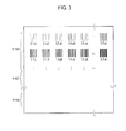
- Fig. 3 is a schematic diagram illustrating pattern images.
- Fig. 4 is a schematic diagram illustrating a correspondence relationship.
- Fig. 5 is a graph illustrating a relationship between a line thickness, a color (darkness), and an average darkness of a pattern image.
- Fig. 6 is a flowchart illustrating a printing control process.
- Figs. 7A through 7D are schematic diagrams illustrating a variation on a pattern image.
- Figs. 8A through 8C are schematic diagrams illustrating a darkness distribution in the thickness direction of a line.
- Fig. 1 is a block diagram illustrating the configuration of a printing system according to an embodiment of the invention.
- a printing system 1 is configured of a PC (personal computer) 10 and a printer 20.
- the PC 10 includes: a hard disk drive (HDD) 11 that stores various types of computer programs such as an OS (operating system), a CAD application program, a raster image generation program, a printer driver program, and so on; a RAM 12 into which these computer programs are loaded; a CPU 13 that executes these computer programs; a ROM 14 that stores a boot program and the like; an external interface (I/F) 15 for connecting to an external device; and an internal I/F 16 for connecting these constituent elements to each other.
- the external I/F 15 connects to the printer 20 and a target printer 30 via a network 40 such as a LAN (local area network).
- a network 40 such as a LAN (local area network).
- the printer 20 is an ink jet serial printer, and includes: a controller 21; a carriage unit 22; a transport unit 23; a UI (user interface) unit 24; an external I/F 25; and an internal I/F 26 for connecting these constituent elements to each other.
- the controller 21 includes an ASIC, a CPU, a ROM, and a RAM, none of which are shown.
- the ASIC and the CPU that executes programs stored in the ROM execute various types of computational processes for a printing control process, which will be described later.
- the "printing control process” is a process for forming a printed image upon a print medium by controlling the carriage unit 22, the transport unit 23, and so on.
- the carriage unit 22 includes a print head 221 and an ink mark sensor unit 222, as well as a carriage motor, a carriage motor driver, ink cartridges, and so on, which are not shown.
- the carriage motor generates a driving force for driving the print head 221 in the main scanning direction.
- the carriage motor driver generates a driving signal needed to drive the carriage motor based on a control signal from the controller 21.
- the ink cartridges hold inks of the colors C (cyan), M (magenta), Y (yellow), and K (black) to be supplied to the print head 221.
- the print head 221 includes nozzles corresponding to the respective colors of ink, and ejects the ink supplied from the ink cartridge onto the print medium in accordance with control signals from the controller 21.
- the ink mark sensor unit 222 includes an LED and a darkness sensor (not shown), and is mounted in the carriage.
- the LED irradiates the surface of the print medium with visible light, and the darkness sensor senses the light reflected by the print medium.
- the sensing target region is, for example, a square that is several mm in side length.
- the ink mark sensor unit 222 moves back and forth in the main scanning direction along with the carriage, and thus the sensing target region also moves in the main scanning direction based on the position of the carriage.
- the darkness sensor then outputs, to the controller 21, a signal indicating a darkness obtained by averaging the darknesses of the sensing target region.
- the ink mark sensor unit 222 is a sensor provided in order to detect skew in the main scanning direction of the landing positions of ink when carrying out bi-directional printing, where printing is carried out both when the carriage is outbound and when the carriage is inbound.
- the ink mark sensor unit 222 is used in order to detect the darkness of a pattern image, as will be described later. Using the existing ink mark sensor unit 222 contributes to cost reduction more than in the case where a darkness sensor is provided separately.
- the transport unit 23 includes a transport motor, transport rollers, a motor driver, and so on, none of which are shown, and transports a recording medium in the sub scanning direction, which is orthogonal to the main scanning direction, based on a control signal from the controller 21.
- the print head 221 and the print medium can be moved relative to each other in the main scanning direction and the sub scanning direction, and thus a two-dimensional printed image can be formed by causing ink droplets to land in various positions upon the print medium.
- the ink mark sensor unit 222 and the print medium can move relative to each other in the main scanning direction and the sub scanning direction, and thus various positions on the print medium can be used as the aforementioned sensing target region.
- the UI unit 24 includes a display unit that displays images and an operation unit that accepts operations.
- the UI unit 24 displays, in the display unit, a print settings screen for accepting settings for various printing conditions, based on a control signal for the controller 21.
- the UI unit 24 accepts settings for printing conditions regarding the print medium and so on through the operation unit, and outputs an operation signal indicating the content of the settings to the controller 21.
- the same file that contains rendering commands for lines is printed by the target printer 30 and the printer 20.
- the target printer 30 is positioned as a printer that prints a line that is to be caused to match with the visual characteristics of a line printed by the printer 20.
- the target printer 30 may be any printer that is capable of printing an image based on a graphic file created using a CAD application program, a pattern image file on which a pattern image for defining a correspondence relationship, mentioned later, is arranged, and so on.
- the target printer 30 need not be the same type of printer as the printer 20, and may be an ink jet printer, a laser printer, or any other type of printer.
- the rendering command for rendering lines contained in a graphic file is converted before printing that graphic file using the printer 20.
- the correspondence relationship is defined in advance, before the graphic file is printed (that is, before the printing control process).
- Fig. 2 is a flowchart illustrating a procedure for defining a correspondence relationship.
- the PC 10 causes the printer 20 to print a pattern image file containing rendering commands for rendering a plurality of pattern images, which will be mentioned later (step S100).
- the PC 10 generates raster image data based on the rendering commands contained in the pattern image file, other commands, and so on by executing the raster image generation program.
- the PC 10 generates print data by carrying out a resolution conversion process, a color conversion process, a halftone process, and a rearranging process through the execution of the printer driver program of the printer 20, and then sends the generated print data to the printer 20.
- the controller 21 of the printer 20 then executes the print by controlling the various elements of the printer 20 based on the print data that has been sent.
- the controller 21 of the printer 20 causes the ink mark sensor unit 222 to measure an average darkness of each pattern image in synchronization with the back-and-forth movement of the carriage (step S105).
- Fig. 3 is a schematic diagram illustrating an example of a pattern image sheet on which a plurality of pattern images are arranged.
- Each pattern image is configured with a plurality of lines parallel to each other disposed at equal intervals with white space interposed therebetween.
- the region occupied by a single pattern image should at least be wider than the sensing target region.
- the lines should be disposed at intervals so that no less than two lines fall within the sensing target region.
- the plurality of lines contained in each pattern image are straight lines that extend in the direction parallel to the sub scanning direction.
- the lines contained within a single pattern image have the same thickness and color.
- the thicknesses of the lines differ by, for example, 0.1 pts from pattern image to pattern image.
- p pattern images having lines of different thicknesses are taken as a single set, and q sets are prepared for each color, for a total of p x q pattern images.
- the PC 10 causes the target printer 30 to print the same pattern image file as the pattern image file used in step S100 (step S110).
- the PC 10 generates raster image data based on the pattern image file by executing the raster image generation program, converts the raster image data into print data of a format suited to printing by the target printer 30 by executing the printer driver program of the target printer 30, and sends the print data to the target printer 30.
- the target printer 30 executes printing based on the print data that has been sent.
- the printer 20 measures the darknesses of the pattern images printed by the target printer 30 by controlling the transport unit 23, the carriage unit 22, and the ink mark sensor unit 222 (step S115).
- the ink mark sensor unit 222 measures the darkness of a square region several mm in side length. Accordingly, a darkness found by averaging an overall region that contains lines and white spaces (referred to as an "average darkness") is what is measured in step S105 and step S115.
- the average darkness of the pattern image printed by the target printer 30 corresponds to a "desired average darkness”.
- the PC 10 stores combinations of line thicknesses and colors that result in an average darkness that matches the average darkness of the pattern image printed by the target printer 30 (the desired average darkness) in association with each other (step S120). Specifically, for example, the results of the measurement of the average darknesses carried out in step S105 and step S115 are sent to the PC 10, and the PC 10 carries out the association using the measurement results that have been sent.
- Fig. 4 shows two tables illustrating relationships between "line thickness” and "K darkness value”, and the average darkness of a pattern image that contains lines rendered according to the "line thickness” and "K darkness value”.
- the left side is a table regarding the pattern images printed by the target printer 30, whereas the right side is a table regarding the pattern images printed by the printer 20.
- the printer 20 sends the information indicated in the two tables shown in Fig. 4 to the PC 10.
- Fig. 5 is a graph illustrating a relationship between the line thickness (the w axis), the K darkness value (the K axis), and the average darkness (the Vk axis).
- the w axis indicates a thicker line the further from the origin
- the K axis indicates a darker darkness for K the further from the origin
- the Vk axis indicates a darker average darkness the further from the origin.
- step S120 the PC 10 searches out, from the table of average darknesses of the pattern images printed by the printer 20, a combination of thickness and K darkness whose average darkness matches the average darkness of a pattern image containing lines of a thickness and a K darkness printed by the target printer 30, and associates these matching combinations with each other.
- a combination of thickness and K darkness whose average darkness matches the average darkness of a pattern image containing lines of a thickness and a K darkness printed by the target printer 30, and associates these matching combinations with each other.
- step S120 a rendering command conversion table, in which (0.1 pt, k1) serving as a combination of a thickness and a K darkness in the pre-conversion rendering command and (0.2 pt, k0) serving as a combination of a thickness and a K darkness in the post-conversion rendering command are associated with each other, is stored in the PC 10. Likewise, correspondence relationships between other combinations of thicknesses and colors for which the average darknesses match are stored as a rendering command conversion table in the HDD 11.
- Fig. 6 is a flowchart illustrating the flow of a printing control process according to this embodiment.
- the process illustrated in Fig. 6 is a process executed when printing, using the printer 20, a graphic file created using the CAD application program.
- the printing is carried out so that the visual characteristics of the lines conform to the result of printing the graphic file using the target printer 30.
- the PC 10 obtains a rendering command (step S200).
- the PC 10 obtains the graphic file to be printed, analyzes the various types of print commands contained in the graphic file, and obtains the rendering command for rendering lines.
- the PC 10 converts the rendering command into a converted command by converting the thicknesses, colors, and so on specified in the rendering command for rendering the lines obtained in step S200 (step S205).
- the PC 10 converts the rendering command for rendering the lines contained in the graphic file.
- the PC 10 converts the rendering command by referring to the aforementioned rendering command conversion table.
- the graphic file contains a rendering command for a line whose color is (0, 0, 0, k1) when a line of a thickness of 0.1 pt in the graphic file is converted into the CMYK color space
- the thickness in that rendering command is converted to 0.2 pt
- the color is converted so that the color in the CMYK color space is (0, 0, 0, k0) (see Fig. 4 and Fig. 5 ).
- other parameters in addition to the thickness and color such as the starting coordinates and ending coordinates of the line, may be specified in a rendering commands for a straight line, those other parameters are not converted, and the values thereof are held over.
- the PC 10 generates image data (raster image data) based on the graphic file containing the converted rendering command, by executing the raster image generation program (step S210). Then, the PC 10 and the printer 20 execute printing based on the image data. Specifically, the PC 10 carries out a resolution conversion process, a color conversion process, a halftone process, and a rearranging process in accordance with the printing conditions by executing the printer driver program of the printer 20, and converts the image data generated in step S210 into print data. The PC 10 then sequentially sends the print data to the printer 20. The printer 20 executes printing based on the print data that has been sent from the PC 10 (step S215). Accordingly, it is possible to cause the visual thicknesses of lines contained in a graphic to match the thickness when the graphic is printed by the target printer 30 with the thickness when the graphic is printed by the printer 20, which makes it possible to prevent erroneous readings of the graphic.
- the technical scope of the invention is not intended to be limited to the aforementioned embodiment, and it goes without saying that various changes can be made within a scope that does not depart from the essential spirit of the invention.
- the aforementioned embodiment describes measuring the average darkness using a pattern image in which lines that extend in the sub scanning direction are disposed at equal intervals.
- the shapes of the ink droplets that land upon the print medium to be longer in the main scanning direction, in which the carriage moves back and forth, than in the sub scanning direction. Accordingly, even if the thicknesses of straight lines as specified in a rendering command are the same, it is possible for the visual thicknesses of the straight lines to differ depending on the direction in which the lines extend.
- the visual thicknesses of lines in printed material can be caused to conform to those of the target printer 30 with a greater degree of precision, in accordance with the direction in which the lines extend (that is, the slope) in the graphic file printed by the printer 20.
- Figs. 7A through 7D illustrate other working examples of pattern images.
- pattern images may be provided for each slope of the straight lines, and associations may then be carried out in the same manner as shown in Fig. 4 .
- Fig. 7C and Fig. 7D pattern images may be provided for each curvature factor of curved lines, and associations may then be carried out in the same manner as shown in Fig. 4 .
- the aforementioned various pattern images may be printed for each type of print medium, and the associations may then be carried out as shown in Fig. 4 for each type of print medium.
- the rendering commands may then be converted based on information indicating correspondence relationships in accordance with the types of print media used when printing the graphic file.
- the aforementioned embodiment describes a configuration in which a darkness sensor provided in the carriage reads a darkness that has been averaged across a square region several mm in side length
- the configuration may be such that the darkness is read using a higher-resolution two-dimensional scanner and the darkness value is obtained from that scanner.
- the average darkness obtained in step S105 and S115 in Fig. 2 may be an integrated value of the line darknesses based on a darkness distribution in the thickness direction of the lines (or may be a value in which the integrated value is divided by a constant thickness W).
- steps S120 combinations of thicknesses and darknesses for which the average darknesses match may be associated with each other.
- the darknesses of the line in the thickness direction are obtained in a plurality of locations along the direction in which the line extends, as shown in Fig. 8A , and the darknesses of pixels whose positions in the thickness direction of the line are the same are averaged; when a darkness distribution is drawn for each position in the thickness direction of the line, the darkness is highest in the center of the line in the thickness direction, and gradually decreases toward the ends in the thickness direction of the line, as shown in Fig. 8B and Fig. 8C . This is because smaller dots are formed at the ends than at the center, the likelihood that dots are formed is lower, and so on.
- the visual thicknesses of the lines are caused to conform by converting the thicknesses, colors and so on specified in the rendering command so that integrated values of the darknesses in each position in the thickness direction of which the line is configured (this corresponds to an area S in Figs. 8B and 8C ) match.
- rendering commands can be converted in the same manner for lines of a color expressed by a plurality of ink colors by using pattern images corresponding to that color.
- thicknesses and the K darknesses are associated with average darknesses in the tables illustrated in Fig.
- a table in which "line thickness”, “C darkness value”, “M darkness value”, “Y darkness value”, and “K darkness value” are associated with “brightness”, “saturation”, and “hue” obtained by reading the result of printing pattern images containing lines in which those thicknesses and CMYK values are specified may be created in order to cause the color of a pattern image containing lines in which a color expressed by a plurality of ink colors is specified to match with more accuracy. Combinations of line thicknesses and CMYK values in which the "brightness”, “saturation”, and “hue” match may then be associated with each other and stored.
- the aforementioned embodiment describes a configuration in which the PC 10 analyzes the rendering command and generates raster image data by executing the raster image generation program, converts the data into print data, and sends the print data to the printer 20, it should be noted that the configuration may be such that the printer 20 is provided with a raster image generation program, a raster image generation circuit, or the like, and the printer 20 obtains the graphic file, analyzes the rendering command, and executes the processes starting with the generation of the raster image data.
- the target printer 30 may, for example, be a printer that is controlled by a PC aside from the PC 10.
Landscapes
- Engineering & Computer Science (AREA)
- General Engineering & Computer Science (AREA)
- Physics & Mathematics (AREA)
- General Physics & Mathematics (AREA)
- Theoretical Computer Science (AREA)
- Record Information Processing For Printing (AREA)
- Accessory Devices And Overall Control Thereof (AREA)
- Facsimile Image Signal Circuits (AREA)
- Color Image Communication Systems (AREA)
Applications Claiming Priority (1)
| Application Number | Priority Date | Filing Date | Title |
|---|---|---|---|
| JP2010254593A JP5482626B2 (ja) | 2010-11-15 | 2010-11-15 | 印刷システム、対応関係情報作成方法 |
Publications (2)
| Publication Number | Publication Date |
|---|---|
| EP2453390A2 true EP2453390A2 (fr) | 2012-05-16 |
| EP2453390A3 EP2453390A3 (fr) | 2014-07-09 |
Family
ID=45557838
Family Applications (1)
| Application Number | Title | Priority Date | Filing Date |
|---|---|---|---|
| EP11188794.9A Withdrawn EP2453390A3 (fr) | 2010-11-15 | 2011-11-11 | Système d'impression et procédé de création d'informations de relation de correspondance |
Country Status (4)
| Country | Link |
|---|---|
| US (1) | US8817327B2 (fr) |
| EP (1) | EP2453390A3 (fr) |
| JP (1) | JP5482626B2 (fr) |
| CN (1) | CN102555548B (fr) |
Cited By (1)
| Publication number | Priority date | Publication date | Assignee | Title |
|---|---|---|---|---|
| JP2020049848A (ja) * | 2018-09-27 | 2020-04-02 | キヤノン株式会社 | 画像処理装置、記録システム、記録装置、記録画像の検知方法、およびプログラム |
Families Citing this family (10)
| Publication number | Priority date | Publication date | Assignee | Title |
|---|---|---|---|---|
| JP6241327B2 (ja) * | 2014-03-10 | 2017-12-06 | セイコーエプソン株式会社 | 印刷装置、印刷システム、及び、印刷装置の制御方法 |
| US10546160B2 (en) | 2018-01-05 | 2020-01-28 | Datamax-O'neil Corporation | Methods, apparatuses, and systems for providing print quality feedback and controlling print quality of machine-readable indicia |
| US10795618B2 (en) * | 2018-01-05 | 2020-10-06 | Datamax-O'neil Corporation | Methods, apparatuses, and systems for verifying printed image and improving print quality |
| US10834283B2 (en) | 2018-01-05 | 2020-11-10 | Datamax-O'neil Corporation | Methods, apparatuses, and systems for detecting printing defects and contaminated components of a printer |
| US10803264B2 (en) | 2018-01-05 | 2020-10-13 | Datamax-O'neil Corporation | Method, apparatus, and system for characterizing an optical system |
| JP7341646B2 (ja) | 2018-09-27 | 2023-09-11 | キヤノン株式会社 | 画像処理装置、画像処理方法、及びプログラム |
| JP7427386B2 (ja) * | 2018-09-27 | 2024-02-05 | キヤノン株式会社 | 情報処理装置、方法、及びプログラム |
| JP7246885B2 (ja) | 2018-09-27 | 2023-03-28 | キヤノン株式会社 | 情報処理装置、方法、及びプログラム |
| JP7134812B2 (ja) | 2018-09-27 | 2022-09-12 | キヤノン株式会社 | 情報処理装置、記録システム、情報処理方法、およびプログラム |
| CN114801522B (zh) * | 2021-01-29 | 2024-11-12 | 杭州旗捷科技股份有限公司 | 打印作业处理方法、芯片、耗材容器及打印机系统 |
Citations (2)
| Publication number | Priority date | Publication date | Assignee | Title |
|---|---|---|---|---|
| JP3770581B2 (ja) | 2000-08-30 | 2006-04-26 | 理想科学工業株式会社 | カラー画像処理方法および装置並びに記録媒体 |
| JP2010091590A (ja) | 2008-09-10 | 2010-04-22 | Ricoh Co Ltd | 画像形成装置、及び画像形成装置の印字方法 |
Family Cites Families (12)
| Publication number | Priority date | Publication date | Assignee | Title |
|---|---|---|---|---|
| CA2129841A1 (fr) * | 1992-04-02 | 1993-10-14 | Richard L. Rylander | Correction de la couleur a l'aide d'une table de consultation quadridimensionnelle |
| US6717700B1 (en) * | 1999-07-01 | 2004-04-06 | Xerox Corporation | Method and system for adjusting binary images |
| US6704123B1 (en) * | 1999-12-17 | 2004-03-09 | Creo Inc. | Method for applying tonal correction to a binary halftone image |
| US6717770B1 (en) * | 2000-03-24 | 2004-04-06 | Seagate Technology Llc | Recording head for applying a magnetic field perpendicular to the magnetizations within magnetic storage media |
| US6967747B2 (en) * | 2001-02-22 | 2005-11-22 | Eastman Kodak Company | Method and system for matching marking device outputs |
| US7032989B2 (en) * | 2002-07-31 | 2006-04-25 | Canon Kabushiki Kaisha | Image processing method and image processing apparatus |
| US7661787B2 (en) * | 2004-02-13 | 2010-02-16 | Seiko Epson Corporation | Printing method, computer-readable medium, printing apparatus, method of manufacturing printing apparatus, printing system, and correction pattern |
| JP2006224419A (ja) * | 2005-02-17 | 2006-08-31 | Seiko Epson Corp | 印刷装置、印刷プログラム、印刷方法、および画像処理装置、画像処理プログラム、画像処理方法、ならびに前記プログラムを記録した記録媒体 |
| JP2006305963A (ja) * | 2005-04-28 | 2006-11-09 | Seiko Epson Corp | 画像処理、補正値取得方法、印刷装置製造方法及び印刷方法 |
| JP4356718B2 (ja) * | 2006-08-25 | 2009-11-04 | セイコーエプソン株式会社 | 印刷装置、及び、印刷方法 |
| JP4668973B2 (ja) * | 2007-11-20 | 2011-04-13 | シャープ株式会社 | 画像処理装置、及びコンピュータプログラム |
| JP2009229768A (ja) * | 2008-03-21 | 2009-10-08 | Noritsu Koki Co Ltd | テストプリント、このテストプリントを出力するカラー画像プリンタ、このテストプリントを用いたカラー画像プリンタの調整方法 |
-
2010
- 2010-11-15 JP JP2010254593A patent/JP5482626B2/ja not_active Expired - Fee Related
-
2011
- 2011-11-11 CN CN201110356954.2A patent/CN102555548B/zh not_active Expired - Fee Related
- 2011-11-11 EP EP11188794.9A patent/EP2453390A3/fr not_active Withdrawn
- 2011-11-14 US US13/295,959 patent/US8817327B2/en not_active Expired - Fee Related
Patent Citations (2)
| Publication number | Priority date | Publication date | Assignee | Title |
|---|---|---|---|---|
| JP3770581B2 (ja) | 2000-08-30 | 2006-04-26 | 理想科学工業株式会社 | カラー画像処理方法および装置並びに記録媒体 |
| JP2010091590A (ja) | 2008-09-10 | 2010-04-22 | Ricoh Co Ltd | 画像形成装置、及び画像形成装置の印字方法 |
Cited By (1)
| Publication number | Priority date | Publication date | Assignee | Title |
|---|---|---|---|---|
| JP2020049848A (ja) * | 2018-09-27 | 2020-04-02 | キヤノン株式会社 | 画像処理装置、記録システム、記録装置、記録画像の検知方法、およびプログラム |
Also Published As
| Publication number | Publication date |
|---|---|
| US20120120425A1 (en) | 2012-05-17 |
| JP2012108569A (ja) | 2012-06-07 |
| US8817327B2 (en) | 2014-08-26 |
| CN102555548B (zh) | 2015-01-14 |
| JP5482626B2 (ja) | 2014-05-07 |
| CN102555548A (zh) | 2012-07-11 |
| EP2453390A3 (fr) | 2014-07-09 |
Similar Documents
| Publication | Publication Date | Title |
|---|---|---|
| US8817327B2 (en) | Printing system and correspondence relationship information creation method to match visual characteristics of different printers | |
| EP3305532B1 (fr) | Dispositif d'inspection d'image, procédé d'inspection d'image, programme et système d'impression à jet d'encre | |
| US7440123B2 (en) | Adaptive printing | |
| US7484821B2 (en) | Method of determining ink ejection method, printing apparatus, and method of manufacturing printing apparatus | |
| US8807698B2 (en) | Inkjet printing apparatus and inkjet printing method | |
| US20140002527A1 (en) | Ink jet recording apparatus and method for detecting faulty discharge in ink jet recording apparatus | |
| JP2008149564A (ja) | インクジェット記録装置および記録モード選択方法 | |
| EP2469835B1 (fr) | Procédé de génération de matrice de seuil | |
| JP6755739B2 (ja) | 画像処理装置、画像処理方法及びプログラム | |
| JP2012071532A (ja) | バーコード印刷制御装置 | |
| US20250150546A1 (en) | Image processing apparatus, control method thereof, and storage medium | |
| US11057528B2 (en) | Information processing apparatus, method and storage medium | |
| CN108290429B (zh) | 确定校准图案的打印机 | |
| US8727529B2 (en) | Barcode printing control device | |
| JP2005125605A (ja) | 画像記録装置及びその制御方法 | |
| JP7708654B2 (ja) | インクジェットプリンタの調整方法、プログラム、及び印刷システム | |
| JP6398783B2 (ja) | 色ムラ検出方法、この色ムラ検出方法を用いたヘッド調整方法、及び、色ムラ検査装置 | |
| US20170274642A1 (en) | Liquid droplet discharging control device, liquid droplet discharging control method, and liquid droplet discharging apparatus | |
| JP2006007533A (ja) | 補正値の設定方法、及び濃度補正用のテストパターン | |
| JP2005212246A (ja) | 環境条件に応じた色変換処理の実行 | |
| JP7427386B2 (ja) | 情報処理装置、方法、及びプログラム | |
| JP2014128901A (ja) | 画像処理装置および画像処理方法 | |
| JP2007069378A (ja) | インクジェット・プリンタ | |
| JP2024014384A (ja) | 記録装置および記録方法 | |
| JP2025044400A (ja) | 画像検査装置、画像検査プログラムおよび画像検査方法 |
Legal Events
| Date | Code | Title | Description |
|---|---|---|---|
| PUAI | Public reference made under article 153(3) epc to a published international application that has entered the european phase |
Free format text: ORIGINAL CODE: 0009012 |
|
| AK | Designated contracting states |
Kind code of ref document: A2 Designated state(s): AL AT BE BG CH CY CZ DE DK EE ES FI FR GB GR HR HU IE IS IT LI LT LU LV MC MK MT NL NO PL PT RO RS SE SI SK SM TR |
|
| AX | Request for extension of the european patent |
Extension state: BA ME |
|
| PUAL | Search report despatched |
Free format text: ORIGINAL CODE: 0009013 |
|
| AK | Designated contracting states |
Kind code of ref document: A3 Designated state(s): AL AT BE BG CH CY CZ DE DK EE ES FI FR GB GR HR HU IE IS IT LI LT LU LV MC MK MT NL NO PL PT RO RS SE SI SK SM TR |
|
| AX | Request for extension of the european patent |
Extension state: BA ME |
|
| RIC1 | Information provided on ipc code assigned before grant |
Ipc: G06K 15/02 20060101AFI20140603BHEP |
|
| 17P | Request for examination filed |
Effective date: 20141119 |
|
| RBV | Designated contracting states (corrected) |
Designated state(s): AL AT BE BG CH CY CZ DE DK EE ES FI FR GB GR HR HU IE IS IT LI LT LU LV MC MK MT NL NO PL PT RO RS SE SI SK SM TR |
|
| STAA | Information on the status of an ep patent application or granted ep patent |
Free format text: STATUS: THE APPLICATION HAS BEEN WITHDRAWN |
|
| 18W | Application withdrawn |
Effective date: 20161202 |