EP2453451A2 - Transformator für eine Windkraftanlage und/oder mit einem Transformator für eine Windkraftanlage installierte Windkrafterzeugungseinrichtungen - Google Patents
Transformator für eine Windkraftanlage und/oder mit einem Transformator für eine Windkraftanlage installierte Windkrafterzeugungseinrichtungen Download PDFInfo
- Publication number
- EP2453451A2 EP2453451A2 EP11179531A EP11179531A EP2453451A2 EP 2453451 A2 EP2453451 A2 EP 2453451A2 EP 11179531 A EP11179531 A EP 11179531A EP 11179531 A EP11179531 A EP 11179531A EP 2453451 A2 EP2453451 A2 EP 2453451A2
- Authority
- EP
- European Patent Office
- Prior art keywords
- wind power
- transformer
- power generating
- power station
- generating facility
- Prior art date
- Legal status (The legal status is an assumption and is not a legal conclusion. Google has not performed a legal analysis and makes no representation as to the accuracy of the status listed.)
- Withdrawn
Links
Images



Classifications
-
- H—ELECTRICITY
- H01—ELECTRIC ELEMENTS
- H01F—MAGNETS; INDUCTANCES; TRANSFORMERS; SELECTION OF MATERIALS FOR THEIR MAGNETIC PROPERTIES
- H01F27/00—Details of transformers or inductances, in general
- H01F27/02—Casings
- H01F27/025—Constructional details relating to cooling
-
- F—MECHANICAL ENGINEERING; LIGHTING; HEATING; WEAPONS; BLASTING
- F03—MACHINES OR ENGINES FOR LIQUIDS; WIND, SPRING, OR WEIGHT MOTORS; PRODUCING MECHANICAL POWER OR A REACTIVE PROPULSIVE THRUST, NOT OTHERWISE PROVIDED FOR
- F03D—WIND MOTORS
- F03D80/00—Details, components or accessories not provided for in groups F03D1/00 - F03D17/00
- F03D80/60—Cooling or heating of wind motors
-
- F—MECHANICAL ENGINEERING; LIGHTING; HEATING; WEAPONS; BLASTING
- F03—MACHINES OR ENGINES FOR LIQUIDS; WIND, SPRING, OR WEIGHT MOTORS; PRODUCING MECHANICAL POWER OR A REACTIVE PROPULSIVE THRUST, NOT OTHERWISE PROVIDED FOR
- F03D—WIND MOTORS
- F03D80/00—Details, components or accessories not provided for in groups F03D1/00 - F03D17/00
- F03D80/80—Arrangement of components within nacelles or towers
- F03D80/82—Arrangement of components within nacelles or towers of electrical components
-
- F—MECHANICAL ENGINEERING; LIGHTING; HEATING; WEAPONS; BLASTING
- F05—INDEXING SCHEMES RELATING TO ENGINES OR PUMPS IN VARIOUS SUBCLASSES OF CLASSES F01-F04
- F05B—INDEXING SCHEME RELATING TO WIND, SPRING, WEIGHT, INERTIA OR LIKE MOTORS, TO MACHINES OR ENGINES FOR LIQUIDS COVERED BY SUBCLASSES F03B, F03D AND F03G
- F05B2250/00—Geometry
- F05B2250/30—Arrangement of components
- F05B2250/36—Arrangement of components in inner-outer relationship, e.g. shaft-bearing arrangements
-
- H—ELECTRICITY
- H01—ELECTRIC ELEMENTS
- H01F—MAGNETS; INDUCTANCES; TRANSFORMERS; SELECTION OF MATERIALS FOR THEIR MAGNETIC PROPERTIES
- H01F27/00—Details of transformers or inductances, in general
- H01F27/08—Cooling; Ventilating
- H01F27/085—Cooling by ambient air
-
- H—ELECTRICITY
- H01—ELECTRIC ELEMENTS
- H01F—MAGNETS; INDUCTANCES; TRANSFORMERS; SELECTION OF MATERIALS FOR THEIR MAGNETIC PROPERTIES
- H01F27/00—Details of transformers or inductances, in general
- H01F27/08—Cooling; Ventilating
- H01F27/10—Liquid cooling
- H01F27/12—Oil cooling
-
- Y—GENERAL TAGGING OF NEW TECHNOLOGICAL DEVELOPMENTS; GENERAL TAGGING OF CROSS-SECTIONAL TECHNOLOGIES SPANNING OVER SEVERAL SECTIONS OF THE IPC; TECHNICAL SUBJECTS COVERED BY FORMER USPC CROSS-REFERENCE ART COLLECTIONS [XRACs] AND DIGESTS
- Y02—TECHNOLOGIES OR APPLICATIONS FOR MITIGATION OR ADAPTATION AGAINST CLIMATE CHANGE
- Y02E—REDUCTION OF GREENHOUSE GAS [GHG] EMISSIONS, RELATED TO ENERGY GENERATION, TRANSMISSION OR DISTRIBUTION
- Y02E10/00—Energy generation through renewable energy sources
- Y02E10/70—Wind energy
- Y02E10/72—Wind turbines with rotation axis in wind direction
Definitions
- the present invention relates to a transformer for wind power station and wind power generating facilities installed with a transformer for wind power station, and more particular, to cooling of a transformer for wind power station.
- JP-A-2006-9596 discloses conventional wind power generating facilities.
- JP-A-2006-9596 discloses an arrangement, in which a whole transformer is accommodated in a tower and a base for mounting the transformer doubles as a base for building the tower. In the case the whole transformer is accommodated in the tower, however, heat generated from the transformer stays in the tower and so an improvement in cooling performance is needed.
- Japanese Patent No. 3715238 discloses an example of wind power generating facilities constructed such that a transformer is accommodated in a tower to achieve an improvement in cooling performance.
- Japanese Patent No. 3715238 discloses an arrangement, in which the transformer and a wall surface of the tower are included in a cooling circuit in the form of a loop and heat generated from the transformer is released from the wall surface of the tower.
- JP-A-63-213330 discloses a technology relating to transformers at large.
- JP-A-63-213330 discloses a transformer for buildings, which is installed on a floor of a building, of which a transformer body is accommodated in an electric room accommodating an electric installation, and in which natural convection cooling type radiators connected to the transformer body are mounted outside the floor.
- the radiators are simply mounted outside the building and consideration is not adequately taken into with respect to efficiency in cooling performance such that an improvement in cooling performance cannot be achieved, for example, at the time of a large heat build-up.
- a transformer for wind power station is accommodated in wind power generating facilities and comprises a transformer body and radiators for release of heat of the transformer body, the transformer body is accommodated in the wind power generating facilities, and an air outside the wind power generating facilities comes into contact with the radiators to cool the same.
- wind power generating facilities comprises the transformer for wind power station, a tower, a nacelle arranged rotatably on a top of the tower, rotor blades mounted on the nacelle to catch wind to revolve, and a generator connected to the rotor blades to rotate a rotor upon revolution of the rotor blades to perform a generating operation.
- a transformer for wind power station and wind power generating facilities according to a first embodiment will be described hereinafter with reference to Fig. 1 .
- Wind power generating facilities 14 schematically comprise a tower (column) 4 built on a base, a nacelle 15 arranged on a top of the tower 4 and supported rotatably with the tower 4 as a support shaft, rotor blades 16 mounted at a forward end of the nacelle 15 to catch the wind to revolve, and a generator 17 connected to the rotor blades 16, and a transformer 18 for wind power station is divided into a body and radiators and arranged inside and outside the wind power generating facility 14 as described hereinafter.
- the transformer 18 for wind power station comprises a transformer body 1, an upper pipe 5, a lower pipe 6, and natural convection cooling type radiators 7, and the transformer body 1 is mounted inside the tower 4.
- the transformer body 1 is formed by filling an insulating, cooling medium 3, such as mineral oil, etc., into a transformer tank 2, and the transformer tank 2 comprises a closed container, in which an iron core and an exciting winding mounted on the iron core are received.
- the natural convection cooling type radiators 7 comprise a plurality of radiating panels (not shown), in which the cooling medium 3 flows. The radiating panels are provided perpendicularly to the upper and lower pipes 5, 6 and aligned a lot in an axial direction of the pipes 5, 6.
- the natural convection cooling type radiator 7 is connected to the transformer tank 2 of the transformer body 1 through the upper pipe 5 and the lower pipe 6 and arranged outside the tower 4.
- the transformer body 1 is arranged inside the tower 4 because high-voltage bushings and wirings are mounted outside the transformer body 1 to cause an accident, such as electrical shock or the like, and failure of the transformer itself upon contact by a person.
- an accident such as electrical shock or the like
- the radiators do not comprise any high-voltage portion and so only an accident such as oil spillage is caused.
- an oil level gauge is mounted to the transformer whereby an alarm is issued when oil is reduced in quantity, and a control system for stoppage of operation is incorporated, so that it is possible to avoid an accident adequately.
- the tank, the cover, the radiators for the transformer are increased in corrosion resistance by coating common steel sheets both indoors and outdoors except in case of being mounted in salt damage regions (along the seaside) and special atmospheres.
- an improvement in corrosion resistance is achieved by adopting, as materials of steel sheet, ferrite stainless steel (stainless steel being more liable to rust, than austenite stainless steel such as commonly known SUS 304, etc.) or austenite stainless steel, changing the thickness of a coated film and the material of coating, performing zinc spraying (a kind of plating) on a coating substrate, performing hot dip galvanizing, or the like.
- ferrite stainless steel stainless steel being more liable to rust, than austenite stainless steel such as commonly known SUS 304, etc.
- austenite stainless steel changing the thickness of a coated film and the material of coating, performing zinc spraying (a kind of plating) on a coating substrate, performing hot dip galvanizing, or the like.
- the generating operation of the wind power generating facility 14 is performed by revolving the rotor blades 16 to rotate a rotor of the generator 17 when the wind velocity is above a predetermined lower limit of wind velocity (generation starting wind velocity or cut-in wind velocity) and below a predetermined upper limit of wind velocity (generation stopping wind velocity or cut-out wind velocity).
- the reason why the generating operation is stopped in case of the wind velocity being larger than the cut-out wind velocity is that the wind power generating facility 14 should be protected against high-wind.
- the cooling medium 3 having flowed into the natural convection cooling type radiators 7 releases heat to the atmosphere through the radiating panels owing to natural convection of an air outside the natural convection cooling type radiators 7 and forced convection of wind blowing outside the tower 4.
- the cooling medium 3, heat of which has been taken by the atmosphere drops in temperature to be decreased in volume, so that it is increased in density to give rise to a downwardly flowing natural convection. Thereby, the cooling medium 3 having released heat goes down in the natural convection cooling type radiators 7 to return again to the transformer tank 2 through the lower pipe 6.
- the necessity for cooling of the transformer 18 is high in some cases and low in some cases.
- electric power generated from the generator 17 correlates to the magnitude of wind velocity such that the larger the wind velocity, the larger the electric power as generated.
- That heating value of the winding which accounts for a large part of the heating value generated from the transformer 18 serving to change the electric power generated from the generator 17 in voltage so as to enable the same to be supplied to a power network, is approximately proportional to the square of the electric power, with the result that the larger the wind velocity, the higher the necessity for cooling of the transformer 18 and conversely the smaller the wind velocity, the lower the necessity for cooling of the transformer 18.
- the natural convection cooling type radiators 7 which releases a large portion of heat generated from the iron core and the exciting winding in the transformer body 1 for wind power station, is arranged outside the tower 4, the wind velocity is large in the case where the necessity for cooling of the transformer 18 is high, in which case forced convection around the natural convection cooling type radiators 7 increases at the same time. Accordingly, an extent of heat release increases and so an improvement in cooling efficiency is achieved.
- air outside the wind power generating facility 14 is made to come into contact with the natural convection cooling type radiators 7 whereby an improvement in cooling efficiency is achieved in the case where heat generation increases to lead to the need of heat release, so that an improvement in cooling performance can be achieved.
- the natural convection cooling type radiators 7 is besides arranged outside the wind power generating facility 14, so that air around the wind power generating facility 14 is made liable to come into contact with the natural convection cooling type radiators 7, thus enabling achieving an improvement in cooling performance.
- the natural convection cooling type radiators 7 small in size.
- the natural convection cooling type radiators 7 serving to release a large portion of heat of the transformer 18 is arranged outside the wind power generating facility 14, it is unnecessary to provide any air conditioner in the tower 4, or it is possible to sharply decrease an air conditioner in size.
- a typical cause for a disadvantage that repair and replacement are necessitated in the operation of the transformer 18 involves spillage of oil used as the cooling medium 3.
- the structure of the transformer is decreased in wall thickness by corrosion or the like to be made thin to make a hole to thereby cause oil spillage and so a portion of the structure being thin in plate thickness is liable to cause oil spillage.
- the natural convection cooling type radiators 7 is small in plate thickness as compared with the transformer tank 2 and the upper and lower pipes 5, 6, so that a danger of generation of oil spillage is the highest in the natural convection cooling type radiators 7.
- the natural convection cooling type radiators 7 is arranged outside the wind power generating facilities 14, so that there is an advantage that simple replacement of the natural convection cooling type radiators 7 is possible and an increase in plate thickness is possible so as to prevent generation of oil spillage because an improvement in cooling efficiency can be achieved by bringing air outside the wind power generating facility 14 into contact with the natural convection cooling type radiators 7.
- a transformer for wind power station and wind power generating facility according to a second embodiment will be described hereinafter with reference to Fig. 2 .
- a duplicate description of the same content as that of the first embodiment is omitted and only a difference between the present embodiment and the first embodiment will be described.
- a different construction of the second embodiment from that of the first embodiment is that plural natural convection cooling type radiators 27 are mounted outside the tower 4 and arranged in two perpendicular directions.
- Wind flowing outside the tower 4 is momently and variously changed in direction.
- the radiating panels of the natural convection cooling type radiators 27 are provided perpendicularly to the upper and lower pipes 5, 6 and aligned a lot in an axial direction of the pipes 5, 6, so that when wind blows perpendicularly to the pipes 5, 6, the wind passes smoothly between the radiating panels and the natural convection cooling type radiators 27 are good in cooling performance, but when wind blows in the axial direction of the pipes 5, 6, the radiating panels in the windward obstruct flow of the wind and causes a decrease in heat release performance.
- the natural convection cooling type radiators 27 are arranged perpendicularly to each other, all the natural convection cooling type radiators 27 are not degraded in cooling performance even when wind blows in any direction, so that all the natural convection cooling type radiators 27 can get an average, less variable heat release performance.
- radiators 27 when instead of the perpendicular arrangement, plural radiators are arranged in plural directions rather than in one direction, all the natural convection cooling type radiators 27 can get an average, less variable heat release performance.
- the natural convection cooling type radiators 27 are not necessarily arranged in two directions but the heat release performance is further averaged and less varied in three directions with no problem.
- direct sunlight as well as wind direction is responsible for a phenomenon that the arrangement of the natural convection cooling type radiators 7 mounted outside the tower 4 affects the cooling performance of the natural convection cooling type radiators 7.
- the natural convection cooling type radiators 7 are exposed to direct sunlight, radiation heat from the sun enters the natural convection cooling type radiators 7 and so heat gain due to radiation from the sun as well as the heating value of the transformer is required to be released to the atmosphere. Therefore, when the natural convection cooling type radiators 7 are arranged outside the wind power generating facility 14, there is a possibility that the natural convection cooling type radiators 7 are increased in temperature by the heat gain from the sun.
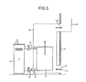
- a transformer for wind power station and wind power generating facility will be described hereinafter with reference to Fig. 3 .
- a duplicate description of the same content as those of the respective embodiments is omitted and only a difference between the present embodiment and the respective embodiments will be described.
- not only a transformer body 1 of the transformer for wind power station but also natural convection cooling type radiators 7 are mounted inside the tower 4 of the wind power generating facility 14.
- a cooling duct 8 is provided inside the tower 4 of the wind power generating facility 14 in a manner to surround the peripheries of the natural convection cooling type radiators 7, and the cooling duct 8 has a lower portion thereof communicated to the atmosphere through an intake port (inlet) 9 and has an upper portion thereof communicated to the atmosphere through an exhaust port (outlet) 10.
- a windbreak plate 12 is mounted outside the exhaust port 10 to prevent wind from blowing into the exhaust port 10.
- the natural convection generated by radiating panels of the natural convection cooling type radiators 7 since the atmospheric air can freely come into and go out of the cooling duct 8 through the intake port 9 and the exhaust port 10, natural convection generated by radiating panels of the natural convection cooling type radiators 7 generates a flow of air 11, which enters the cooling duct 8 from the intake port 9, flows upward among the radiating panels in the cooling duct 8, and flows out of the tower 4 from the exhaust port 10.
- the natural convection generated by the radiating panels of the natural convection cooling type radiators 7 indicates a flow generated when the atmospheric air having taken heat from the radiating panels of the natural convection cooling type radiators 7 to be made warm is increased in volume to be decreased in density to flow upward.
- windbreak plate 12 is mounted outside the exhaust port 10 to prevent wind from blowing into the exhaust port 10 to prevent wind from blowing into the exhaust port 10
- wind flowing outside the tower 4 can be blown into the intake port 9 but not into the exhaust port 10, so that the wind agrees in flow path with the flow (the intake port 9 ⁇ the cooling duct 8 ⁇ the exhaust port 10) of the natural convection and the velocity of flow generated by natural convection in the cooling duct 8 is further increased by forced convection, which accompanies the wind. That is, heat of a cooling medium 3 is released directly to the atmosphere from the natural convection cooling type radiators 7 by natural convection of air outside the natural convection cooling type radiators 7 and forced convection generated when the wind blowing outside the tower 4 blows into the cooling duct 8.
- air outside the wind power generating facility 14 is made to come into contact with the natural convection cooling type radiators 7 to thereby lead to an increase in heat release and an improvement in cooling efficiency is achieved in the case where heat release is needed, so that an improvement in cooling performance can be achieved.
- an arrangement in which the intake port 9 of the cooling duct 8 is disposed on a lower side and the exhaust port 10 is disposed on an upper side, makes it possible to generate air flow from the intake port 9 on the lower side to the exhaust port 10 on the upper side owing to natural convection generated by radiating panels of the natural convection cooling type radiators 7 and to achieve an improvement in cooling performance.
- the windbreak plate 12 since the windbreak plate 12 is mounted on the exhaust port 10 outside the exhaust port 10, the atmosphere can be prevented from flowing to the intake port 9 from the exhaust port 10 and agrees in flow direction with the natural convection, so that it is possible to achieve a further improvement in cooling performance.
- a transformer for wind power station and wind power generating facility will be described hereinafter with reference to Fig. 4 .
- a duplicate description of the same content as those of the respective embodiments is omitted and only a difference between the fourth embodiment and the respective embodiments will be described.
- a transformer body 21 is accommodated inside a tower 24 of the wind power generating facility 14 and an outer wall of the tower 24 is double-structured to form a tower outer wall double-structured flow passage 13 communicated vertically.
- an inner wall surface side of the outer wall of the tower 24 is included in the tower outer wall double-structured flow passage 13.
- the tower outer wall double-structured flow passage 13 and a tank 22 of the transformer body 21 are connected to each other by an upper pipe 25 and a lower pipe 26.
- a cooling medium 23 in the transformer tank 22 takes heat generated from an iron core and a winding to rise in temperature to be decreased in density.
- the cooling medium 23 having been decreased in density flows through the upper pipe 25 into an upper portion of the tower outer wall double-structured flow passage 13 formed in the outer wall of the tower 24.
- Wind blowing outside the tower 24 flows outside the tower outer wall double-structured flow passage 13, which is double-structured, and the cooling medium 23 comes into contact with an inner wall surface of the tower 24 to release heat to the atmosphere through the wall surface.
- the cooling medium having released heat to the atmosphere drops in temperature and is increased in density to go down in the tower outer wall double-structured flow passage 13, which is double-structured, to form a flow returning to the transformer tank 22 from the lower pipe 26.
- the respective embodiments may further comprise a wind direction meter for measurement of wind direction and radiators may be moved in a manner to keep out of a lee side according to a wind direction as measured.
- a high cooling performance can be obtained at all times to be further advantageous.
Landscapes
- Engineering & Computer Science (AREA)
- Mechanical Engineering (AREA)
- Sustainable Development (AREA)
- Sustainable Energy (AREA)
- Chemical & Material Sciences (AREA)
- Combustion & Propulsion (AREA)
- Life Sciences & Earth Sciences (AREA)
- General Engineering & Computer Science (AREA)
- Power Engineering (AREA)
- Physics & Mathematics (AREA)
- Thermal Sciences (AREA)
- Wind Motors (AREA)
- Transformer Cooling (AREA)
Applications Claiming Priority (1)
| Application Number | Priority Date | Filing Date | Title |
|---|---|---|---|
| JP2010253378A JP2012102692A (ja) | 2010-11-12 | 2010-11-12 | 風力発電用変圧器及び風力発電用変圧器を搭載する風力発電設備 |
Publications (2)
| Publication Number | Publication Date |
|---|---|
| EP2453451A2 true EP2453451A2 (de) | 2012-05-16 |
| EP2453451A3 EP2453451A3 (de) | 2013-12-25 |
Family
ID=44735837
Family Applications (1)
| Application Number | Title | Priority Date | Filing Date |
|---|---|---|---|
| EP11179531.6A Withdrawn EP2453451A3 (de) | 2010-11-12 | 2011-08-31 | Transformator für eine Windkraftanlage und/oder mit einem Transformator für eine Windkraftanlage installierte Windkrafterzeugungseinrichtungen |
Country Status (4)
| Country | Link |
|---|---|
| US (1) | US20120119505A1 (de) |
| EP (1) | EP2453451A3 (de) |
| JP (1) | JP2012102692A (de) |
| CN (1) | CN102468038A (de) |
Cited By (7)
| Publication number | Priority date | Publication date | Assignee | Title |
|---|---|---|---|---|
| EP2933481A1 (de) * | 2014-04-15 | 2015-10-21 | Areva Wind GmbH | Luftkanal für Windenergieanlage, Windenergieanlage, Verfahren zur Herstellung eines Luftkanals und Verfahren zur Nachrüstung einer Windenergieanlage mit einem Luftkanal |
| WO2016000715A1 (en) * | 2014-07-02 | 2016-01-07 | Vestas Wind Systems A/S | A wind turbine with a tower-mounted heat exchange structure |
| EP2977996A1 (de) * | 2014-07-21 | 2016-01-27 | Siemens Aktiengesellschaft | Drosselspule eines Stromrichters |
| WO2017008817A1 (en) * | 2015-07-16 | 2017-01-19 | Mhi Vestas Offshore Wind A/S | A cooling panel assembly for a wind turbine tower and a wind turbine tower |
| EP2551518A3 (de) * | 2011-07-25 | 2017-06-21 | Hitachi Industrial Equipment Systems Co., Ltd. | Transformator zur Windenergieerzeugung und Windenergieerzeugungssystem |
| EP2792879A3 (de) * | 2013-04-15 | 2018-02-28 | Hitachi, Ltd. | Windenergieerzeugungssystem |
| CN113431748A (zh) * | 2021-06-23 | 2021-09-24 | 华能灌云清洁能源发电有限责任公司 | 风电机组散热系统 |
Families Citing this family (9)
| Publication number | Priority date | Publication date | Assignee | Title |
|---|---|---|---|---|
| JP6200637B2 (ja) * | 2012-08-28 | 2017-09-20 | 株式会社日立産機システム | 油入変圧器 |
| DE102015217035A1 (de) * | 2015-09-04 | 2017-03-09 | Wobben Properties Gmbh | Windenergieanlage und Verfahren zum Steuern einer Kühlung einer Windenergieanlage |
| DE102015122855A1 (de) * | 2015-12-28 | 2017-06-29 | Wobben Properties Gmbh | Windenergieanlage und Kühlvorrichtung für eine Windenergieanlage |
| CN111465765A (zh) | 2017-12-14 | 2020-07-28 | 贝斯特罗株式会社 | 塔式风力发电设备的拆卸方法 |
| CN108417356A (zh) * | 2018-04-12 | 2018-08-17 | 广东瑞智电力科技有限公司 | 一种海上风电升压系统的植物油变压器 |
| DE102019114655A1 (de) * | 2019-05-31 | 2020-12-03 | Rwe Renewables Gmbh | Hohlstrukturelement einer Windenergieanlage |
| US12276123B2 (en) | 2020-07-20 | 2025-04-15 | Besterra Co., Ltd. | Dismantling method of tower-type wind power generation system |
| CN113539629B (zh) * | 2021-07-19 | 2023-07-25 | 远景能源有限公司 | 一种半开放式大功率设备冷却系统及冷却方法 |
| CN114783730B (zh) * | 2022-04-24 | 2024-09-10 | 广东电网有限责任公司广州供电局 | 海上风电用变压器及其散热器件 |
Citations (3)
| Publication number | Priority date | Publication date | Assignee | Title |
|---|---|---|---|---|
| JPS63213330A (ja) | 1987-02-27 | 1988-09-06 | Takenaka Komuten Co Ltd | ビル用変圧器 |
| JP3715238B2 (ja) | 1999-07-14 | 2005-11-09 | アロイス・ヴォベン | 閉冷却回路を有する風力利用設備 |
| JP2006009596A (ja) | 2004-06-22 | 2006-01-12 | Tohoku Electric Power Engineering & Construction Co Ltd | 変電開閉設備を内蔵した風力発電装置およびその施工方法 |
Family Cites Families (12)
| Publication number | Priority date | Publication date | Assignee | Title |
|---|---|---|---|---|
| JPS58225617A (ja) * | 1982-06-22 | 1983-12-27 | Mitsubishi Electric Corp | 変圧器冷却装置 |
| DE19947915A1 (de) * | 1999-10-06 | 2001-04-12 | Abb Research Ltd | Kühlsystem für Baugruppen in einer Windkraftanlage |
| JP2003258463A (ja) * | 2002-03-07 | 2003-09-12 | Hitachi Kokusai Electric Inc | 筐体の熱交換構造 |
| US7168251B1 (en) * | 2005-12-14 | 2007-01-30 | General Electric Company | Wind energy turbine |
| PL2002120T3 (pl) * | 2006-03-25 | 2010-04-30 | Clipper Windpower Inc | System obsługi ciepła w turbinie wiatrowej |
| JP2007273529A (ja) * | 2006-03-30 | 2007-10-18 | Japan Radio Co Ltd | ヒートシンク及び屋外設置型電子機器放熱装置 |
| BRPI0717365A2 (pt) * | 2006-11-03 | 2013-10-15 | Vestas Wind Sys As | Sistema de aquecimento, turbina eólica ou parque eólico industrial, método para utilizar o excedente térmico de um ou mais componentes de turbina eólica, e uso de um método. |
| US7615884B2 (en) * | 2007-01-30 | 2009-11-10 | Mcmastercorp, Inc. | Hybrid wind turbine system, apparatus and method |
| ES2330491B1 (es) * | 2007-05-25 | 2010-09-14 | GAMESA INNOVATION & TECHNOLOGY, S.L. | Sistema de climatizacion para aerogeneradores. |
| PL2151833T3 (pl) * | 2008-08-07 | 2013-08-30 | Starkstrom Geraetebau Gmbh | Układ transformatorowy |
| US7748946B2 (en) * | 2008-12-09 | 2010-07-06 | General Electric Company | Cooling system and method for wind turbine components |
| US7850418B2 (en) * | 2009-10-28 | 2010-12-14 | General Electric Company | System and method to facilitate maintenance on a wind turbine |
-
2010
- 2010-11-12 JP JP2010253378A patent/JP2012102692A/ja active Pending
-
2011
- 2011-08-24 CN CN201110253619XA patent/CN102468038A/zh active Pending
- 2011-08-31 US US13/222,186 patent/US20120119505A1/en not_active Abandoned
- 2011-08-31 EP EP11179531.6A patent/EP2453451A3/de not_active Withdrawn
Patent Citations (3)
| Publication number | Priority date | Publication date | Assignee | Title |
|---|---|---|---|---|
| JPS63213330A (ja) | 1987-02-27 | 1988-09-06 | Takenaka Komuten Co Ltd | ビル用変圧器 |
| JP3715238B2 (ja) | 1999-07-14 | 2005-11-09 | アロイス・ヴォベン | 閉冷却回路を有する風力利用設備 |
| JP2006009596A (ja) | 2004-06-22 | 2006-01-12 | Tohoku Electric Power Engineering & Construction Co Ltd | 変電開閉設備を内蔵した風力発電装置およびその施工方法 |
Cited By (12)
| Publication number | Priority date | Publication date | Assignee | Title |
|---|---|---|---|---|
| EP2551518A3 (de) * | 2011-07-25 | 2017-06-21 | Hitachi Industrial Equipment Systems Co., Ltd. | Transformator zur Windenergieerzeugung und Windenergieerzeugungssystem |
| EP2792879A3 (de) * | 2013-04-15 | 2018-02-28 | Hitachi, Ltd. | Windenergieerzeugungssystem |
| EP2933481A1 (de) * | 2014-04-15 | 2015-10-21 | Areva Wind GmbH | Luftkanal für Windenergieanlage, Windenergieanlage, Verfahren zur Herstellung eines Luftkanals und Verfahren zur Nachrüstung einer Windenergieanlage mit einem Luftkanal |
| WO2015158788A1 (en) * | 2014-04-15 | 2015-10-22 | Areva Wind Gmbh | Air duct for wind power plant, wind power plant, method of manufacturing an air duct and method of retrofitting a wind power plant with an air duct |
| US10539121B2 (en) | 2014-04-15 | 2020-01-21 | Areva Wind Gmbh | Wind power plant air duct and method of manufacturing the same |
| WO2016000715A1 (en) * | 2014-07-02 | 2016-01-07 | Vestas Wind Systems A/S | A wind turbine with a tower-mounted heat exchange structure |
| US10018188B2 (en) | 2014-07-02 | 2018-07-10 | Vestas Wind Systems A/S | Wind turbine with a tower-mounted heat exchange structure |
| EP2977996A1 (de) * | 2014-07-21 | 2016-01-27 | Siemens Aktiengesellschaft | Drosselspule eines Stromrichters |
| WO2017008817A1 (en) * | 2015-07-16 | 2017-01-19 | Mhi Vestas Offshore Wind A/S | A cooling panel assembly for a wind turbine tower and a wind turbine tower |
| US10264782B2 (en) | 2015-07-16 | 2019-04-23 | Mhi Vestas Offshore Wind A/S | Cooling panel assembly for a wind turbine tower and a wind turbine tower |
| CN113431748A (zh) * | 2021-06-23 | 2021-09-24 | 华能灌云清洁能源发电有限责任公司 | 风电机组散热系统 |
| CN113431748B (zh) * | 2021-06-23 | 2022-08-23 | 华能灌云清洁能源发电有限责任公司 | 风电机组散热系统 |
Also Published As
| Publication number | Publication date |
|---|---|
| JP2012102692A (ja) | 2012-05-31 |
| CN102468038A (zh) | 2012-05-23 |
| US20120119505A1 (en) | 2012-05-17 |
| EP2453451A3 (de) | 2013-12-25 |
Similar Documents
| Publication | Publication Date | Title |
|---|---|---|
| EP2453451A2 (de) | Transformator für eine Windkraftanlage und/oder mit einem Transformator für eine Windkraftanlage installierte Windkrafterzeugungseinrichtungen | |
| US9228566B2 (en) | Wind turbine comprising a cooling circuit | |
| JP5727739B2 (ja) | 風車構造を冷却する方法及びシステム | |
| CA2379161C (en) | Wind energy facility with a closed cooling circuit | |
| CN102903484B (zh) | 变压器以及风力发电系统 | |
| TWI532914B (zh) | Wind power generation equipment | |
| EP2518315B1 (de) | Windturbinen-Stromerzeugungseinrichtungen | |
| CN113454399A (zh) | 冷却面板系统 | |
| CN101523119A (zh) | 用于电子设备的热冷却 | |
| Fiorino | Achieving high chilled-water delta Ts | |
| TWI598506B (zh) | Wind power equipment | |
| WO2013185767A1 (en) | A wind turbine with a tower mounted heat exchange structure | |
| CN102966249A (zh) | 一种用于车载移动式直流融冰装置的集装箱 | |
| US20110018278A1 (en) | Device and method for capturing energy from building systems | |
| EP2722463B1 (de) | Technisches Gebäudemodul | |
| US20070229205A1 (en) | Arrangemetn for Cooling of Components of Wind Energy Installations | |
| US20250354757A1 (en) | Industrial cooling system to control the water temperature of the process using a hybrid of air-cooled and water-cooled phases | |
| JP3079337U (ja) | 電気設備格納用屋外鉄箱 | |
| JP6797541B2 (ja) | 熱交換器 | |
| CN102394540A (zh) | 一种单轴耦合的双风力发电机 | |
| CN202160373U (zh) | 通过塔壁散热的风机冷却系统 | |
| Quality | Concept | |
| CN108026900B (zh) | 风能设备和用于控制风能设备的冷却的方法 | |
| CN215578090U (zh) | 一种干式变压器新型散热装置 | |
| CN109413959B (zh) | 小型基站室外机柜的空气柜外自循环降温节能装置 |
Legal Events
| Date | Code | Title | Description |
|---|---|---|---|
| PUAI | Public reference made under article 153(3) epc to a published international application that has entered the european phase |
Free format text: ORIGINAL CODE: 0009012 |
|
| 17P | Request for examination filed |
Effective date: 20111209 |
|
| AK | Designated contracting states |
Kind code of ref document: A2 Designated state(s): AL AT BE BG CH CY CZ DE DK EE ES FI FR GB GR HR HU IE IS IT LI LT LU LV MC MK MT NL NO PL PT RO RS SE SI SK SM TR |
|
| AX | Request for extension of the european patent |
Extension state: BA ME |
|
| PUAL | Search report despatched |
Free format text: ORIGINAL CODE: 0009013 |
|
| AK | Designated contracting states |
Kind code of ref document: A3 Designated state(s): AL AT BE BG CH CY CZ DE DK EE ES FI FR GB GR HR HU IE IS IT LI LT LU LV MC MK MT NL NO PL PT RO RS SE SI SK SM TR |
|
| AX | Request for extension of the european patent |
Extension state: BA ME |
|
| RIC1 | Information provided on ipc code assigned before grant |
Ipc: H01F 27/02 20060101AFI20131121BHEP Ipc: F03D 11/00 20060101ALI20131121BHEP |
|
| STAA | Information on the status of an ep patent application or granted ep patent |
Free format text: STATUS: THE APPLICATION IS DEEMED TO BE WITHDRAWN |
|
| 18D | Application deemed to be withdrawn |
Effective date: 20140626 |