EP2453460A2 - Procédé de recyclage des déchets des lampes fluorescentes - Google Patents
Procédé de recyclage des déchets des lampes fluorescentes Download PDFInfo
- Publication number
- EP2453460A2 EP2453460A2 EP20110188398 EP11188398A EP2453460A2 EP 2453460 A2 EP2453460 A2 EP 2453460A2 EP 20110188398 EP20110188398 EP 20110188398 EP 11188398 A EP11188398 A EP 11188398A EP 2453460 A2 EP2453460 A2 EP 2453460A2
- Authority
- EP
- European Patent Office
- Prior art keywords
- glass tube
- fluorescent lamp
- peeling liquid
- tube
- waste fluorescent
- Prior art date
- Legal status (The legal status is an assumption and is not a legal conclusion. Google has not performed a legal analysis and makes no representation as to the accuracy of the status listed.)
- Withdrawn
Links
- 238000000034 method Methods 0.000 title claims abstract description 70
- 239000002699 waste material Substances 0.000 title claims abstract description 49
- 238000004064 recycling Methods 0.000 title claims abstract description 22
- 239000011521 glass Substances 0.000 claims abstract description 101
- 239000007788 liquid Substances 0.000 claims abstract description 65
- 239000000463 material Substances 0.000 claims description 10
- XLYOFNOQVPJJNP-UHFFFAOYSA-N water Substances O XLYOFNOQVPJJNP-UHFFFAOYSA-N 0.000 claims description 3
- 238000007599 discharging Methods 0.000 claims 2
- 229910052753 mercury Inorganic materials 0.000 description 21
- 239000000126 substance Substances 0.000 description 21
- QSHDDOUJBYECFT-UHFFFAOYSA-N mercury Chemical compound [Hg] QSHDDOUJBYECFT-UHFFFAOYSA-N 0.000 description 20
- 238000010586 diagram Methods 0.000 description 11
- 239000002002 slurry Substances 0.000 description 8
- WABPQHHGFIMREM-UHFFFAOYSA-N lead(0) Chemical compound [Pb] WABPQHHGFIMREM-UHFFFAOYSA-N 0.000 description 5
- 238000005516 engineering process Methods 0.000 description 4
- OAICVXFJPJFONN-UHFFFAOYSA-N Phosphorus Chemical compound [P] OAICVXFJPJFONN-UHFFFAOYSA-N 0.000 description 3
- 239000005355 lead glass Substances 0.000 description 3
- 230000035515 penetration Effects 0.000 description 3
- 239000000843 powder Substances 0.000 description 3
- 229910052761 rare earth metal Inorganic materials 0.000 description 3
- 229910001369 Brass Inorganic materials 0.000 description 2
- NBIIXXVUZAFLBC-UHFFFAOYSA-N Phosphoric acid Chemical compound OP(O)(O)=O NBIIXXVUZAFLBC-UHFFFAOYSA-N 0.000 description 2
- 235000010210 aluminium Nutrition 0.000 description 2
- 239000010951 brass Substances 0.000 description 2
- 238000011109 contamination Methods 0.000 description 2
- 230000007613 environmental effect Effects 0.000 description 2
- OSWPMRLSEDHDFF-UHFFFAOYSA-N methyl salicylate Chemical compound COC(=O)C1=CC=CC=C1O OSWPMRLSEDHDFF-UHFFFAOYSA-N 0.000 description 2
- 229910052756 noble gas Inorganic materials 0.000 description 2
- 150000002910 rare earth metals Chemical class 0.000 description 2
- XOLBLPGZBRYERU-UHFFFAOYSA-N tin dioxide Chemical compound O=[Sn]=O XOLBLPGZBRYERU-UHFFFAOYSA-N 0.000 description 2
- 229910001887 tin oxide Inorganic materials 0.000 description 2
- WFKWXMTUELFFGS-UHFFFAOYSA-N tungsten Chemical compound [W] WFKWXMTUELFFGS-UHFFFAOYSA-N 0.000 description 2
- 229910052721 tungsten Inorganic materials 0.000 description 2
- 239000010937 tungsten Substances 0.000 description 2
- 229910000497 Amalgam Inorganic materials 0.000 description 1
- RYGMFSIKBFXOCR-UHFFFAOYSA-N Copper Chemical compound [Cu] RYGMFSIKBFXOCR-UHFFFAOYSA-N 0.000 description 1
- 229910052693 Europium Inorganic materials 0.000 description 1
- 241001465754 Metazoa Species 0.000 description 1
- 229910052771 Terbium Inorganic materials 0.000 description 1
- 239000002253 acid Substances 0.000 description 1
- XAGFODPZIPBFFR-UHFFFAOYSA-N aluminium Chemical compound [Al] XAGFODPZIPBFFR-UHFFFAOYSA-N 0.000 description 1
- 229910052782 aluminium Inorganic materials 0.000 description 1
- 229910000147 aluminium phosphate Inorganic materials 0.000 description 1
- LDDQLRUQCUTJBB-UHFFFAOYSA-O azanium;hydrofluoride Chemical compound [NH4+].F LDDQLRUQCUTJBB-UHFFFAOYSA-O 0.000 description 1
- 238000004140 cleaning Methods 0.000 description 1
- 229910052802 copper Inorganic materials 0.000 description 1
- 239000010949 copper Substances 0.000 description 1
- 230000007423 decrease Effects 0.000 description 1
- 238000001035 drying Methods 0.000 description 1
- 230000000694 effects Effects 0.000 description 1
- OGPBJKLSAFTDLK-UHFFFAOYSA-N europium atom Chemical compound [Eu] OGPBJKLSAFTDLK-UHFFFAOYSA-N 0.000 description 1
- 238000011010 flushing procedure Methods 0.000 description 1
- 235000013305 food Nutrition 0.000 description 1
- 229960001047 methyl salicylate Drugs 0.000 description 1
- 239000000203 mixture Substances 0.000 description 1
- 239000004576 sand Substances 0.000 description 1
- 235000014102 seafood Nutrition 0.000 description 1
- 239000005361 soda-lime glass Substances 0.000 description 1
- 150000003457 sulfones Chemical class 0.000 description 1
- GZCRRIHWUXGPOV-UHFFFAOYSA-N terbium atom Chemical compound [Tb] GZCRRIHWUXGPOV-UHFFFAOYSA-N 0.000 description 1
- 229910052727 yttrium Inorganic materials 0.000 description 1
- VWQVUPCCIRVNHF-UHFFFAOYSA-N yttrium atom Chemical compound [Y] VWQVUPCCIRVNHF-UHFFFAOYSA-N 0.000 description 1
Images





Classifications
-
- H—ELECTRICITY
- H01—ELECTRIC ELEMENTS
- H01J—ELECTRIC DISCHARGE TUBES OR DISCHARGE LAMPS
- H01J9/00—Apparatus or processes specially adapted for the manufacture, installation, removal, maintenance of electric discharge tubes, discharge lamps, or parts thereof; Recovery of material from discharge tubes or lamps
- H01J9/52—Recovery of material from discharge tubes or lamps
-
- H—ELECTRICITY
- H01—ELECTRIC ELEMENTS
- H01J—ELECTRIC DISCHARGE TUBES OR DISCHARGE LAMPS
- H01J9/00—Apparatus or processes specially adapted for the manufacture, installation, removal, maintenance of electric discharge tubes, discharge lamps, or parts thereof; Recovery of material from discharge tubes or lamps
- H01J9/50—Repairing or regenerating used or defective discharge tubes or lamps
-
- Y—GENERAL TAGGING OF NEW TECHNOLOGICAL DEVELOPMENTS; GENERAL TAGGING OF CROSS-SECTIONAL TECHNOLOGIES SPANNING OVER SEVERAL SECTIONS OF THE IPC; TECHNICAL SUBJECTS COVERED BY FORMER USPC CROSS-REFERENCE ART COLLECTIONS [XRACs] AND DIGESTS
- Y02—TECHNOLOGIES OR APPLICATIONS FOR MITIGATION OR ADAPTATION AGAINST CLIMATE CHANGE
- Y02W—CLIMATE CHANGE MITIGATION TECHNOLOGIES RELATED TO WASTEWATER TREATMENT OR WASTE MANAGEMENT
- Y02W30/00—Technologies for solid waste management
- Y02W30/50—Reuse, recycling or recovery technologies
- Y02W30/60—Glass recycling
-
- Y—GENERAL TAGGING OF NEW TECHNOLOGICAL DEVELOPMENTS; GENERAL TAGGING OF CROSS-SECTIONAL TECHNOLOGIES SPANNING OVER SEVERAL SECTIONS OF THE IPC; TECHNICAL SUBJECTS COVERED BY FORMER USPC CROSS-REFERENCE ART COLLECTIONS [XRACs] AND DIGESTS
- Y02—TECHNOLOGIES OR APPLICATIONS FOR MITIGATION OR ADAPTATION AGAINST CLIMATE CHANGE
- Y02W—CLIMATE CHANGE MITIGATION TECHNOLOGIES RELATED TO WASTEWATER TREATMENT OR WASTE MANAGEMENT
- Y02W30/00—Technologies for solid waste management
- Y02W30/50—Reuse, recycling or recovery technologies
- Y02W30/82—Recycling of waste of electrical or electronic equipment [WEEE]
Definitions
- This invention generally relates the recycling method of the waste fluorescent lamp, in particular, without crushing the fluorescent tube. Therefore, it can be recycled the materials without splashing the mercury.
- the fluorescent lamp basically consists of the glass tube which is formed the fluorescent substance layer in its internal surface and electrodes which is attached both edges of the glass tube.
- a noble gas and mercury with 2 ⁇ 4 hPa (*1 atmosphere ⁇ 1,013 hPa) are contained in the glass tube.
- the environmental contamination by mercury concerns the health risk to the human body through the food chain via animals and seafood.
- the purpose of this invention is to provide the secure recycling method for waste fluorescent lamps without splashing mercury.
- the another purpose of this invention is to provide the peeling method for the formed layer inside the glass tube in the fluorescent lamp without crushing.
- the other purpose of this invention is to provide the recycling method for waste fluorescent lamps regardless of its shape.
- the idea of this invention is gotten from the fact that the inner space of the glass tube in the fluorescent lamp is maintained as vacuum state.
- the negative pressure (state that the pressure is lower than the normal atmospheric pressure) is constructed inside the glass tube because of the vacuum state.
- the peeling liquid is inserted and fulfilled into the glass tube.
- the formed layer inside the glass tube will be peeled by the liquid. And then the peeled layer will be discharged with the peeling liquid.
- the “layer” in this document contains all layers such as the fluorescent substance layer formed inside the glass tube.
- the composition of the layer will be varied depending on the type of the fluorescent lamp.
- the transparent conducting film layer is also included onto the rapid-start type fluorescent lamp.
- the protection layer or reflection layer may be formed.
- the mercury enclosed inside the glass tube is attached to the layer, therefore the mercury will also be removed from the glass tube when the layer is discharged.
- the glass tube, ferrules, electrodes, lead wire and glass chip etc. can be recovered from the waste fluorescent lamp after the layers are peeled off. And the materials which consist of the layer, and the mercury can be recovered from the discharged peeling liquid.
- this invention can apply to not only hot cathode fluorescent lamp (HCFL) but also cold cathode fluorescent lamp (CCFL). Therefore, the definition of "fluorescent lamp” in this document includes both of the HCFL and CCFL.
- the peeling liquid will be fulfilled into the glass tube using the vacuum status inside the glass tube in the fluorescent lamp. Only the layer formed inside the glass tube will be removed by the peeling liquid, so the resources such as the glass tube etc. can effectively be recovered and recycled without crushing the waste fluorescent lamp.
- the architecture of the straight shape rapid-start type fluorescent lamp is briefly described as an example of the waste fluorescent lamp.
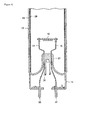
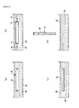
- the ferrules (14) are attached both edges of the glass tube (12) in the straight shape fluorescent lamp (10) as shown in Figure 1 .
- the electrodes (16) are supported by the lead wires (18) respectively as shown in Figure 2 .
- the lead wire is connected to the pin (22) in the ferrule (14), via stem (20).
- the stem (20) has the exhaust tube (24) for vacuuming the air when the fluorescent lamp is manufactured.
- the exhaust tube is communicated with inside of the glass tube and the base end section of the exhaust tube is chipped off (sealed) after the glass tube had evacuated and then the noble gas and mercury (liquid mercury or mercury amalgam such as Zn-Hg, Ti-Hg) had enclosed.
- the mainframe of the glass tube (12) is made from soda-lime glass and the stem (20) is made from lead glass.
- the transparent conducting film layer (26) which is consists of tin oxide film is formed inside the glass tube.
- the fluorescent substance layer (28) is formed onto the transparent conducting film layer.
- the fluorescent substance layer consists of the fluorescent substances which include the rare earth elements such as europium, yttrium and terbium etc. and phosphor powder.
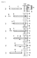
- this tank is called peeling liquid tank.
- the protrusion (34) which has spiky edge is installed on the bottom of the peeling liquid tank (32).
- the duct (36) for draining the slurry settled down on the bottom of the peeling liquid tank is also installed.
- the valve (38) is installed on the duct.
- the slurry storage tank (40) is arranged onto the outlet of the duct.
- the duct (36), valve (38) and slurry storage tank (40) are only shown in Figure 3 (G) .
- the solution which includes the sulfone acid, phosphoric acid, ammonium hydrogen fluoride and methyl salicylate is used (as an example).
- the protrusion tool (42) will penetrate the ferrule (14) in the upper edge of the waste fluorescent lamp and crush the base end section of the exhaust tube (24).
- the forced discharge using the air pump can be available.
- the forced discharge connect the pump to the crushed exhaust tube in the upper edge of the glass tube (12) and intake the air.
- the peeled transparent conducting film layer and fluorescent substance layer are included into the discharged peeling liquid (30).
- the mercury attached to the transparent conducting film layer and fluorescent substance layer will also be discharged into the peeling liquid tank with the peeling liquid.
- the transparent conducting film layer, fluorescent substance layer and mercury will be settled down on the bottom of the peeling liquid tank (32) as the slurry (44).
- the waste fluorescent lamp After the peeling liquid is completely discharged, the waste fluorescent lamp will be transferred to the next process.
- the waste fluorescent lamp which is peeled off the transparent conducting film layer and fluorescent substance layer should be allocated near the 2 units of disc cutter (52) that is rotated and driven by the motors (50) respectively.
- both edges (parts include the electrode and ferrule) of the glass tube (56) in the waste fluorescent lamp (54) will be cut off by the disc cutter.
- the plain glass tube (58) can be recovered after the drying process is complete.
- the recovered plain glass tube can be reused as the glass tube of the recycled fluorescent lamp.
- the recycling process has adopted for the waste fluorescent lamp with ferrules. However, this process can also be adopted for the waste fluorescent lamp which has removed its ferrules. For this case, the procedure for crushing the base ends of the exhaust tube will be easy because there is no ferrule.
- the crushing method can be available for any form.
- the drill unit can be used instead of the protrusion and protrusion tool.
- the waste fluorescent lamp has held vertically on the peeling liquid tank and the peeling liquid has fulfilled into the inside of glass tube.
- the contents of embodiment is not limited above. It can be available for the another method that the waste fluorescent lamp is immersed under the peeling liquid tank. This method is called 2nd embodiment hereafter and described below:
- Figure 6 is for describing the recycling process procedure for the straight shape waste fluorescent lamp.
- the same number is attached.
- the description for the process same as the 1st embodiment will be omitted.
- the waste fluorescent lamp (10) is horizontally held under the peeling liquid (30) in the peeling liquid tank (32).
- the transparent conducting film layer and fluorescent substance layer formed inside the glass tube will be peeled off by the peeling liquid.
- the recycling process for the straight shape waste fluorescent lamp can be adopted any shape fluorescent lamp such as the circle shape. Furthermore, it can be applied to the bulb-shape fluorescent lamp.
- the transparent conducting film layer and fluorescent substance layer formed inside the glass tube will be peeled off by the peeling liquid.
- the peeled layers will naturally be discharged with the peeling liquid from the crushed exhaust tube (66) in the glass tube to the peeling liquid tank In this case, an air should be flown into the glass tube via one side of the exhaust tube and the peeling liquid should naturally be discharged from other side of the exhaust tube.
- the peeling liquid When an air is input to one side of the glass tube, the peeling liquid can forcedly be discharged from other side of the glass tube.
- the peeling liquid can also be discharged naturally both sides of the exhaust tube.
- the method for creating hole on the glass tube is adopted the exhaust tube crushing.
- the sand blast can be used for creating hole near the stem, or the cutter can also be used for cutting off the edge of the glass tube.
- the CCFL is typically used as the light source of the LED backlight and has the small diameter of the glass tube. Therefore, when the CCFL is recycled, it is recommended that the CCFL should be processed to immerse under the peeling liquid as described in the 2nd embodiment. In this case, it is recommended that the cutter should be used to cut off the both edges of the glass tube and creating hole.
Landscapes
- Engineering & Computer Science (AREA)
- Manufacturing & Machinery (AREA)
- Processing Of Solid Wastes (AREA)
- Vessels And Coating Films For Discharge Lamps (AREA)
Applications Claiming Priority (1)
| Application Number | Priority Date | Filing Date | Title |
|---|---|---|---|
| JP2010254951A JP5599289B2 (ja) | 2010-11-15 | 2010-11-15 | 廃蛍光灯のリサイクル方法 |
Publications (2)
| Publication Number | Publication Date |
|---|---|
| EP2453460A2 true EP2453460A2 (fr) | 2012-05-16 |
| EP2453460A3 EP2453460A3 (fr) | 2012-11-28 |
Family
ID=45092205
Family Applications (1)
| Application Number | Title | Priority Date | Filing Date |
|---|---|---|---|
| EP20110188398 Withdrawn EP2453460A3 (fr) | 2010-11-15 | 2011-11-09 | Procédé de recyclage des déchets des lampes fluorescentes |
Country Status (7)
| Country | Link |
|---|---|
| US (1) | US20120125371A1 (fr) |
| EP (1) | EP2453460A3 (fr) |
| JP (1) | JP5599289B2 (fr) |
| KR (1) | KR20120089183A (fr) |
| CN (1) | CN102543629A (fr) |
| CA (1) | CA2756620A1 (fr) |
| TW (1) | TW201233766A (fr) |
Cited By (1)
| Publication number | Priority date | Publication date | Assignee | Title |
|---|---|---|---|---|
| FR2999102A1 (fr) * | 2012-12-11 | 2014-06-13 | Veolia Proprete | Procede de decoupe a froid d'une lampe |
Families Citing this family (3)
| Publication number | Priority date | Publication date | Assignee | Title |
|---|---|---|---|---|
| CN106216352B (zh) * | 2016-07-29 | 2019-09-24 | 杨聪 | 重复利用日光灯中荧光粉的系统 |
| CN106140790B (zh) * | 2016-07-29 | 2019-09-06 | 河北君业科技股份有限公司 | 日光灯的再利用工艺 |
| KR102475153B1 (ko) | 2020-12-30 | 2022-12-06 | 강원대학교산학협력단 | 폐형광체 분말로부터 희토류 원소를 회수하는 방법 |
Citations (2)
| Publication number | Priority date | Publication date | Assignee | Title |
|---|---|---|---|---|
| JPS62116685A (ja) | 1985-04-30 | 1987-05-28 | エムア−ルテイ− システム アクチ−ボラグ | 水銀蒸気放電灯から発光性材料を再生するための方法および装置 |
| JP2001286828A (ja) | 2000-04-07 | 2001-10-16 | Kazuo Yashiki | 蛍光管の乾式洗浄機 |
Family Cites Families (11)
| Publication number | Priority date | Publication date | Assignee | Title |
|---|---|---|---|---|
| US485833A (en) * | 1892-11-08 | Two-way sanitary trap | ||
| US3839085A (en) * | 1972-03-27 | 1974-10-01 | Richards Corp | Tube surface scraping |
| JPS4932488A (fr) * | 1972-07-24 | 1974-03-25 | ||
| JPS51121989A (en) * | 1975-04-16 | 1976-10-25 | Toshiba Corp | Method of washing tubular bulb |
| EP0298035B1 (fr) * | 1987-06-29 | 1994-06-01 | Recytec S.A. | Méthode pour recycler des tubes fluorescents et des tubes de télévision |
| JPH05275015A (ja) * | 1992-03-27 | 1993-10-22 | Toshiba Lighting & Technol Corp | 管球の破壊方法および管球破壊装置 |
| DE19734687C1 (de) * | 1997-08-11 | 1999-01-28 | Ald Vacuum Techn Gmbh | Induktionskappentrennverfahren |
| DE19815486A1 (de) * | 1998-04-07 | 1999-10-28 | Richard Kurig | Verfahren zur Aufarbeitung von gebrauchten Leuchtstofflampen zur Glasrohrrückgewinnung |
| TW494438B (en) * | 2000-03-30 | 2002-07-11 | Toshiba Lighting & Amp Technol | Method of recycling fluorescent substance for fluorescent lamp, recycled fluorescent lamp and lighting apparatus using thereof |
| JP4136295B2 (ja) * | 2000-03-30 | 2008-08-20 | 東芝ライテック株式会社 | 蛍光ランプの再生方法 |
| US7727429B2 (en) * | 2005-03-25 | 2010-06-01 | Osram Sylvania Inc. | Core for molding a ceramic discharge vessel |
-
2010
- 2010-11-15 JP JP2010254951A patent/JP5599289B2/ja not_active Expired - Fee Related
-
2011
- 2011-10-31 CA CA 2756620 patent/CA2756620A1/fr not_active Abandoned
- 2011-11-09 EP EP20110188398 patent/EP2453460A3/fr not_active Withdrawn
- 2011-11-11 US US13/294,704 patent/US20120125371A1/en not_active Abandoned
- 2011-11-11 CN CN2011103570323A patent/CN102543629A/zh active Pending
- 2011-11-14 TW TW100141454A patent/TW201233766A/zh unknown
- 2011-11-14 KR KR1020110118062A patent/KR20120089183A/ko not_active Withdrawn
Patent Citations (2)
| Publication number | Priority date | Publication date | Assignee | Title |
|---|---|---|---|---|
| JPS62116685A (ja) | 1985-04-30 | 1987-05-28 | エムア−ルテイ− システム アクチ−ボラグ | 水銀蒸気放電灯から発光性材料を再生するための方法および装置 |
| JP2001286828A (ja) | 2000-04-07 | 2001-10-16 | Kazuo Yashiki | 蛍光管の乾式洗浄機 |
Cited By (3)
| Publication number | Priority date | Publication date | Assignee | Title |
|---|---|---|---|---|
| FR2999102A1 (fr) * | 2012-12-11 | 2014-06-13 | Veolia Proprete | Procede de decoupe a froid d'une lampe |
| WO2014091108A1 (fr) * | 2012-12-11 | 2014-06-19 | Veolia Proprete | Procédé de découpe à froid d'une lampe |
| US9496113B2 (en) | 2012-12-11 | 2016-11-15 | Veolia Proprete | Method for cold-cutting a lamp |
Also Published As
| Publication number | Publication date |
|---|---|
| CN102543629A (zh) | 2012-07-04 |
| EP2453460A3 (fr) | 2012-11-28 |
| JP2012109043A (ja) | 2012-06-07 |
| US20120125371A1 (en) | 2012-05-24 |
| CA2756620A1 (fr) | 2012-05-15 |
| KR20120089183A (ko) | 2012-08-09 |
| TW201233766A (en) | 2012-08-16 |
| JP5599289B2 (ja) | 2014-10-01 |
Similar Documents
| Publication | Publication Date | Title |
|---|---|---|
| EP2453460A2 (fr) | Procédé de recyclage des déchets des lampes fluorescentes | |
| KR100441731B1 (ko) | 화상 표시 장치와 그 해체 처리 방법과 부품의 회수 방법 | |
| EP0993016B1 (fr) | Ecran à plasma et méthode de son démontage | |
| PL1989223T3 (pl) | Sposób i urządzenie do wyodrębniania gruczołu stawonoga | |
| EP1271617A3 (fr) | Lampe à décharge dans un gaz à basse pression avec couche fluorescente | |
| FI85781B (fi) | Foerfarande och anordning foer aotervinning av lysaemnet ur lysroer. | |
| CN1136857A (zh) | 低压汞蒸气放电灯 | |
| ES3034540T3 (en) | Device for processing a multiple glazing unit | |
| CN100419945C (zh) | 荧光灯 | |
| TW200746224A (en) | Fluorescent lamp, manufacturing method therefor, lighting device using the fluorescent lamp, and display device | |
| CN102464296A (zh) | 一种mems结构切割分离方法 | |
| JP4086163B2 (ja) | プラズマディスプレイパネルの再利用システム | |
| CN220774305U (zh) | 晶圆划片结构及uv解胶机 | |
| US8123583B2 (en) | Production method for discharge lamps | |
| JP3799334B2 (ja) | プラズマディスプレイパネルの再利用方法 | |
| CN206199313U (zh) | 一种用于浸泡实验室玻璃器皿的酸缸 | |
| JP4338544B2 (ja) | 廃蛍光管の処理方法及び廃蛍光管処理装置 | |
| KR20060006130A (ko) | 프라즈마 디스플레이 판넬의 재이용방법 | |
| JP2005340038A (ja) | プラズマディスプレイパネルの再利用方法 | |
| JP2004305900A (ja) | プラズマディスプレイパネルの再利用方法 | |
| CN208438883U (zh) | 一种耐溶剂耐磨的胶刮 | |
| KR20060037041A (ko) | 플라즈마 디스플레이 패널 | |
| KR100363680B1 (ko) | 플라즈마 디스플레이 패널의 제조방법 | |
| JP4299191B2 (ja) | 蛍光管の浄化処理方法 | |
| KR20120057849A (ko) | 고효율 광 추출이 가능한 유리기판 및 그의 제조방법 |
Legal Events
| Date | Code | Title | Description |
|---|---|---|---|
| PUAI | Public reference made under article 153(3) epc to a published international application that has entered the european phase |
Free format text: ORIGINAL CODE: 0009012 |
|
| AK | Designated contracting states |
Kind code of ref document: A2 Designated state(s): AL AT BE BG CH CY CZ DE DK EE ES FI FR GB GR HR HU IE IS IT LI LT LU LV MC MK MT NL NO PL PT RO RS SE SI SK SM TR |
|
| AX | Request for extension of the european patent |
Extension state: BA ME |
|
| PUAL | Search report despatched |
Free format text: ORIGINAL CODE: 0009013 |
|
| AK | Designated contracting states |
Kind code of ref document: A3 Designated state(s): AL AT BE BG CH CY CZ DE DK EE ES FI FR GB GR HR HU IE IS IT LI LT LU LV MC MK MT NL NO PL PT RO RS SE SI SK SM TR |
|
| AX | Request for extension of the european patent |
Extension state: BA ME |
|
| RIC1 | Information provided on ipc code assigned before grant |
Ipc: H01J 9/52 20060101ALI20121023BHEP Ipc: H01J 9/50 20060101AFI20121023BHEP |
|
| STAA | Information on the status of an ep patent application or granted ep patent |
Free format text: STATUS: THE APPLICATION IS DEEMED TO BE WITHDRAWN |
|
| 18D | Application deemed to be withdrawn |
Effective date: 20130529 |