EP2453601A1 - Dispositif multiplexeur optique d insertion-extraction reconfigurable permettant d obtenir une incertitude de longueur d onde sans aucune résistance - Google Patents
Dispositif multiplexeur optique d insertion-extraction reconfigurable permettant d obtenir une incertitude de longueur d onde sans aucune résistance Download PDFInfo
- Publication number
- EP2453601A1 EP2453601A1 EP09846998A EP09846998A EP2453601A1 EP 2453601 A1 EP2453601 A1 EP 2453601A1 EP 09846998 A EP09846998 A EP 09846998A EP 09846998 A EP09846998 A EP 09846998A EP 2453601 A1 EP2453601 A1 EP 2453601A1
- Authority
- EP
- European Patent Office
- Prior art keywords
- optical
- optical signals
- signals
- switch
- switches
- Prior art date
- Legal status (The legal status is an assumption and is not a legal conclusion. Google has not performed a legal analysis and makes no representation as to the accuracy of the status listed.)
- Withdrawn
Links
Images


Classifications
-
- H—ELECTRICITY
- H04—ELECTRIC COMMUNICATION TECHNIQUE
- H04J—MULTIPLEX COMMUNICATION
- H04J14/00—Optical multiplex systems
- H04J14/02—Wavelength-division multiplex systems
- H04J14/0201—Add-and-drop multiplexing
- H04J14/0202—Arrangements therefor
- H04J14/0204—Broadcast and select arrangements, e.g. with an optical splitter at the input before adding or dropping
-
- H—ELECTRICITY
- H04—ELECTRIC COMMUNICATION TECHNIQUE
- H04J—MULTIPLEX COMMUNICATION
- H04J14/00—Optical multiplex systems
- H04J14/02—Wavelength-division multiplex systems
- H04J14/0201—Add-and-drop multiplexing
- H04J14/0202—Arrangements therefor
- H04J14/021—Reconfigurable arrangements, e.g. reconfigurable optical add/drop multiplexers [ROADM] or tunable optical add/drop multiplexers [TOADM]
- H04J14/0212—Reconfigurable arrangements, e.g. reconfigurable optical add/drop multiplexers [ROADM] or tunable optical add/drop multiplexers [TOADM] using optical switches or wavelength selective switches [WSS]
-
- G—PHYSICS
- G02—OPTICS
- G02B—OPTICAL ELEMENTS, SYSTEMS OR APPARATUS
- G02B6/00—Light guides; Structural details of arrangements comprising light guides and other optical elements, e.g. couplings
- G02B6/10—Light guides; Structural details of arrangements comprising light guides and other optical elements, e.g. couplings of the optical waveguide type
- G02B6/12—Light guides; Structural details of arrangements comprising light guides and other optical elements, e.g. couplings of the optical waveguide type of the integrated circuit kind
- G02B6/12007—Light guides; Structural details of arrangements comprising light guides and other optical elements, e.g. couplings of the optical waveguide type of the integrated circuit kind forming wavelength selective elements, e.g. multiplexer, demultiplexer
- G02B6/12009—Light guides; Structural details of arrangements comprising light guides and other optical elements, e.g. couplings of the optical waveguide type of the integrated circuit kind forming wavelength selective elements, e.g. multiplexer, demultiplexer comprising arrayed waveguide grating [AWG] devices, i.e. with a phased array of waveguides
-
- H—ELECTRICITY
- H04—ELECTRIC COMMUNICATION TECHNIQUE
- H04B—TRANSMISSION
- H04B10/00—Transmission systems employing electromagnetic waves other than radio-waves, e.g. infrared, visible or ultraviolet light, or employing corpuscular radiation, e.g. quantum communication
- H04B10/50—Transmitters
-
- H—ELECTRICITY
- H04—ELECTRIC COMMUNICATION TECHNIQUE
- H04J—MULTIPLEX COMMUNICATION
- H04J14/00—Optical multiplex systems
- H04J14/02—Wavelength-division multiplex systems
- H04J14/0201—Add-and-drop multiplexing
- H04J14/0202—Arrangements therefor
- H04J14/0205—Select and combine arrangements, e.g. with an optical combiner at the output after adding or dropping
-
- H—ELECTRICITY
- H04—ELECTRIC COMMUNICATION TECHNIQUE
- H04J—MULTIPLEX COMMUNICATION
- H04J14/00—Optical multiplex systems
- H04J14/02—Wavelength-division multiplex systems
- H04J14/0201—Add-and-drop multiplexing
- H04J14/0202—Arrangements therefor
- H04J14/021—Reconfigurable arrangements, e.g. reconfigurable optical add/drop multiplexers [ROADM] or tunable optical add/drop multiplexers [TOADM]
- H04J14/02122—Colourless, directionless or contentionless [CDC] arrangements
-
- H—ELECTRICITY
- H04—ELECTRIC COMMUNICATION TECHNIQUE
- H04J—MULTIPLEX COMMUNICATION
- H04J14/00—Optical multiplex systems
- H04J14/02—Wavelength-division multiplex systems
- H04J14/03—WDM arrangements
- H04J14/0307—Multiplexers; Demultiplexers
-
- H—ELECTRICITY
- H04—ELECTRIC COMMUNICATION TECHNIQUE
- H04J—MULTIPLEX COMMUNICATION
- H04J14/00—Optical multiplex systems
- H04J14/02—Wavelength-division multiplex systems
- H04J14/0201—Add-and-drop multiplexing
- H04J14/0215—Architecture aspects
- H04J14/0217—Multi-degree architectures, e.g. having a connection degree greater than two
-
- H—ELECTRICITY
- H04—ELECTRIC COMMUNICATION TECHNIQUE
- H04J—MULTIPLEX COMMUNICATION
- H04J14/00—Optical multiplex systems
- H04J14/02—Wavelength-division multiplex systems
- H04J14/0201—Add-and-drop multiplexing
- H04J14/0215—Architecture aspects
- H04J14/0219—Modular or upgradable architectures
Definitions
- the invention relates to the field of optical communications, and in particular to a reconfigurable optical add/drop multiplexing device for enabling a totally inresistant colorless (wavelength irrelevance).
- DWDM Dense Wavelength Division Multiplexing
- the service type has transited from a Time Division Multiplexing (TDM) service-based circuit switching service to an IP-based data service.
- TDM Time Division Multiplexing
- the intelligence of the networks requires the DWDM devices to provide the reconfigurable functions based on the wavelength, i.e., wavelength Reconfigurable Optical Add Drop Multiplexing (ROADM), which can flexibly enable the add and drop multiplexing function of the wavelength and implement remote configuration.
- the ROADM can realize any point-to-point connection without manual deployment, and can realize the adding, dropping and straight-through configuration of the single wavelength.
- the ROADM technology can increase the flexibility of the Wavelength Division Multiplexing (WDM) network, make the network operators remotely and dynamically control the wavelength transmission path, and effectively reduce the operation and maintenance cost of the operators. Meanwhile, with the development of the network scale and the diversity of the service types, a multidirectional intelligent ROADM system which can realize the service broadcast function needs to be provided.
- Fig. 1 shows a diagram of an existing ROADM device.
- the device comprises three parts which are a circuit direction, a dropping unit and an adding unit.
- the optical signals which are transmitted through the optical fibres from the direction 1 to the direction X respectively, enter into a dispersion compensation module in the direction (the module is selected according to the dispersion and the dispersion tolerance of the system) to be implemented with dispersion compensation, the optical signals then enter into an Optical Preamplifier (OPA) in the corresponding direction to be amplified to make up for the line loss.
- OPA Optical Preamplifier
- the WSS in the circuit direction of the direction broadcasts the inputted signals which are inputted to the direction from each direction, and multiplex it with selected wavelength signals from the signals inputted by the adding unit. And then, the WSS outputs the wavelength signals which are implemented with the optical multiplexing to the dispersion compensation module (the module is selected according to the dispersion and dispersion tolerance of the system), and then to the circuit optical fibre after the signals are amplified by the Optical Booster Amplifier (OBA).
- OBA Optical Booster Amplifier
- the wavelength scheduling among the X circuit direction can be realized through the matching of the units, and the wavelength scheduling can be realized through remotely controlling the WSS by the network manager of the devices.
- the dropping unit in Fig. 1 consists of couplers, WSSes, Optical Amplifiers (OAs), tunable filters and receivers (RXes), wherein the optical signals in the direction 1 ⁇ X which are broadcasted and dropped through the coupler in the circuit direction are distributed into multiple groups through power allocation by the coupler of the dropping unit (for example, the broadcasted optical signals can be distributed into 2 groups by adopting 1 ⁇ 2 couplers, and can be distributed into 4 groups by adopting 1 ⁇ 4 couplers, and so on).
- the broadcasted optical signals can be distributed into 2 groups by adopting 1 ⁇ 2 couplers, and can be distributed into 4 groups by adopting 1 ⁇ 4 couplers, and so on).
- Each group is outputted after the WSS selects the wavelength signals which need to be dropped from the optical signals inputted in each direction to perform optical multiplexing, and is outputted to the tunable filter to select the dropping wavelength after being amplified by the OA. And it is received by the RX, so as to realize the directionless and colorless dropping functions. But each group cannot have the same wavelength dropping.
- the same wavelength can be divided into multiple groups of droppings by the couplers.
- the tunable filter can be realized by the WSS. And the reconfiguration of the dropping wavelength can be realized by the network manager of the devices through remotely controlling the WSS and the tunable filter.
- the adding unit in Fig. 1 consists of WSSes, couplers 1, OAs, couplers 2 and transmitters (TX), wherein each group of the optical signals transmitted by the TX are outputted to the coupler 2 after optical multiplexing by the coupler 1 of the group and then being amplified by the OA.
- the coupler 2 outputs the multiplexed optical signals to the WSS in each direction in the form of broadcast, and the WSS in each direction outputs each group of the optical signals to the WSS in the circuit direction in the corresponding direction after selectively implementing optical multiplexing for the optical signals.
- the directionless and colorless dropping functions can be realized when the TX is the one with tunable wavelengths.
- each group cannot have the same wavelength adding, the same wavelength can be divided into multiple groups, and can be realized by the WSS through selectively implementing optical multiplexing for each group of signals.
- the reconfiguration of the adding wavelength can be realized by the network manager of the devices through remotely controlling the WSS and the TX with tunable wavelengths.
- the related art only can realize part of the colorless, i.e., the dropping wavelength under each wavelength selection and the allocation unit cannot be the same, and the adding wavelength under each optical multiplexing and the allocation unit cannot be the same.
- the adjustable optical filter array is immature, although the WSS is adopted to realize the reconfigurable dropping at present, the WSS apparatus is expensive.
- the WSS apparatus with more than 9 ports is immature, and multiple WSSes are needed when realizing the adding and dropping with more wavelengths.
- the ROADM device has a high cost and a large size.
- the present invention aims to provide a reconfigurable optical add/drop multiplexing device for enabling totally inresistant colorless, which can realize add and drop with totally inresistant colorless.
- the reconfigurable optical add/drop multiplexing device for enabling totally inresistant colorless comprises a: a dropping unit and an adding unit, wherein the dropping unit is configured to separate optical signals of multiple wavelengths in direction 1 ⁇ X which are broadcast inputted from a circuit direction, switch the optical signals of multiple wavelengths in the direction 1 ⁇ X to any corresponding output port through multiple N ⁇ N optical switches, and transmit the optical signals to corresponding RXs after combining the optical signals through the corresponding K ⁇ 1 couplers/optical switches; and the adding unit is configured to broadcast the optical signals which are transmitted from TXs to multiple N ⁇ N optical switches through N 1 ⁇ K couplers/optical switches, switch the optical signals to any corresponding output port through the respective N ⁇ N optical switches, and multiplex the corresponding optical signals in the 1 ⁇ X direction and output the corresponding optical signals to the circuit direction, wherein X is an integer greater than or equal to 2, and K and N are both integers.
- the dropping unit is provided with 1 ⁇ M demultiplexers in the direction 1 ⁇ X and Y N ⁇ N optical switches, wherein the 1 ⁇ M demultiplexers in the direction 1 ⁇ X are configured to separate the optical signals of different wavelengths in the direction 1 ⁇ X which are broadcast inputted from the circuit direction, and output to the Y N ⁇ N optical switches; and the Y N ⁇ N optical switches are configured to switch the input optical signals of multiple wavelengths in each direction to any corresponding output port, and transmit the corresponding K ⁇ 1 couplers/optical switches, wherein X is an integer greater than or equal to 2; K, Y, M and N are integers greater than or equal to 1; K is greater than or equal to Y, N is greater than or equal to M, and Y ⁇ N is greater than or equal to X ⁇ M.
- the dropping unit is also provided with 1 ⁇ L couplers in the direction 1 ⁇ X, wherein L is an integer greater than or equal to 1, and is configured to separate the optical signals of multiple wavelengths in the direction 1 ⁇ X which are broadcast inputted from the circuit direction into L parts through the 1 ⁇ L couplers respectively, and output the separated optical signals to the 1 ⁇ M demultiplexers in the direction 1 ⁇ X.
- an optical amplifier is arranged between each of the 1 ⁇ L couplers in the direction 1 ⁇ X and the 1 ⁇ M demultiplexers in the direction 1 ⁇ X, and is configured to amplify the optical signals which are outputted from the 1 ⁇ L couplers and output the amplified optical signals to the 1 ⁇ M demultiplexers in the direction 1 ⁇ X.
- the adding unit is provided with M ⁇ 1 multiplexers in the direction 1 ⁇ X and Y N ⁇ N optical switches, wherein the Y N ⁇ N optical switches are configured to switch the optical signals of multiple direction broadcast from the 1 ⁇ K couplers/optical switches to any corresponding output port; the M ⁇ 1 multiplexers in the direction 1 ⁇ X are configured to output the optical signals after multiplexing the optical signals in the corresponding direction outputted by the N ⁇ N optical switches.
- the adding unit is further provided with L ⁇ 1 couplers in the direction 1 ⁇ X, wherein L is an integer greater than or equal to 1; and the adding unit is configured to couple signals outputted from the M ⁇ 1 multiplexer through the L ⁇ 1 couplers and output and broadcast the coupled signals to the circuit direction.
- an OA is set between each of the L ⁇ 1 couplers in the direction 1 ⁇ X and the M ⁇ 1 multiplexers in the direction 1 ⁇ X, and is configured to amplify the optical signals which are outputted from the M ⁇ 1 multiplexers in the direction 1 ⁇ X and output the amplified optical signals to the L ⁇ 1 couplers in the direction 1 ⁇ X.
- the 1 ⁇ M demultiplexers of the dropping unit adopt the technical devices such as array waveguide gratings (AWG) or thin film filters (TFF); and the M ⁇ 1 multiplexers of the adding unit adopt the AWG, or TFF, or couplers.
- AWG array waveguide gratings
- TFF thin film filters
- the N ⁇ N optical switches of the adding unit and the dropping unit need to block the input optical signals which do not need to be outputted through the N ⁇ N optical switches respectively, that is, make the optical signals not to be outputted through any port; and when the adding unit adopts the 1 ⁇ K optical switches and the dropping unit adopts the K ⁇ 1 optical switches, the N ⁇ N optical switches of the adding unit and the dropping unit do not need to resist the input optical signals which do not need to be outputted through the N ⁇ N optical switches respectively.
- 1 ⁇ K couplers/optical switches of the adding unit and the K ⁇ 1 couplers/optical switches of the dropping unit are all integrated in a module.
- the first port of each coupler outputs through a parallel optical fiber connector MPO connector, the second port outputs through another MPO connector, and so on.
- the M ⁇ 1 multiplexers of the adding unit, the 1 ⁇ M demultiplexers of the dropping unit and the N ⁇ N optical switches are all provided with MPO connectors.
- the 1 ⁇ M demultiplexers of the dropping unit, the N ⁇ N optical switches and the K ⁇ 1 couplers/optical switches are connected through optical fiber of the MPO connectors; and the M ⁇ 1 demultiplexers of the adding unit, the N ⁇ N optical switches and the 1 ⁇ K couplers/optical switches are connected through the optical fibers of the MPO connectors.
- the reconfigurable optical add/drop multiplexing device has the beneficial effects that: on the basis that the reconfigurable optical add/drop multiplexing device for enabling totally inresistant colorless can realize the irrelevance in the adding direction and the dropping direction, the broadcasting function of the signals in the adding and circuit direction, and the loopback function in the circuit direction, the add/drop totally inresistant colorless is realized; the optical fiber connection and the equipment volume are simplified by utilizing the parallel optical fiber connector MPO connector; and the equipment cost is reduced.
- the reconfigurable optical add/drop multiplexing device for enabling totally inresistant colorless realizes the totally inresistant colorless of the adding and dropping by improving the adding unit and the dropping unit, based on the present reconfigurable optical add/drop multiplexing device.
- the device comprises a wavelength scheduling unit, a dropping unit and an adding unit.
- the wavelength scheduling unit is configured for wavelength scheduling in circuit direction 1 ⁇ X, signal broadcasting in the circuit direction and loopbacking in the circuit direction.
- the wavelength scheduling unit comprises: an OPA in the direction 1 ⁇ X, a coupler in the circuit direction of the direction 1 ⁇ X, a WSS in the direction 1 ⁇ X and an OBA in the direction 1 ⁇ X.
- a dispersion compensation module in the direction 1 ⁇ X can be configured according to the dispersion of the system and the dispersion tolerance degree.
- X is an integer greater than or equal to 2
- X is a direction number of ROADM nodes, that is, dimensionality
- the wavelength scheduling can be performed remotely by a network manager of the device.
- the dropping unit is configured to separate optical signals of multiple wavelengths in the direction 1 ⁇ X which are broadcast inputted from the circuit direction, switch optical signals of multiple wavelengths in the direction 1 ⁇ X to any corresponding output port through multiple N ⁇ N optical switches, and sending the received optical signals to corresponding RX after combining the signals by the corresponding K ⁇ 1 couplers/optical switches.
- the dropping unit comprises: a coupler in the direction 1 ⁇ X, an OA in the direction 1 ⁇ X, a 1 ⁇ M demultiplexer in the direction 1 ⁇ X (in which, K is an integer, M is the number of wavelengths in a single direction), Y N ⁇ N optical switches (in which, Y is an integer, N ⁇ M, and Y ⁇ N ⁇ M), N K ⁇ 1 couplers/optical switches (in which, K is an integer, and K ⁇ Y), and a RX.
- the signals are amplified by the OA and output to the 1 ⁇ M demultiplexer in the direction 1 ⁇ X. Then the demultiplexer separates the optical signals of respective wavelengths and outputs the signals to respective N ⁇ N optical switches which then switch the input optical signals of multiple wavelengths in each direction to any a corresponding output port.
- the K ⁇ 1 coupler/optical switch outputs the optical signals selected by each N ⁇ N optical switch to the RX after multiplexing the signals.
- the coupler in the direction 1 ⁇ X can be the 1 ⁇ L coupler in the direction 1 ⁇ X, wherein L is an integer greater than or equal to 1.
- the optical signals in respective directions broadcasted to the dropping unit through the coupler in the circuit direction are split into L parts by the 1 ⁇ L coupler respectively, wherein each part is outputted to the 1 ⁇ M demultiplexer in the direction 1 ⁇ X after being amplified by the OA.
- the N ⁇ N optical switch and the K ⁇ 1 coupler/optical switch can be controlled remotely by a network manager of the device to realize the reconfiguration of the dropping wavelength.
- the adding unit is configured to broadcast optical signals which are sent from the TX to multiple N ⁇ N optical switches through N 1 ⁇ K couplers/optical switches, switch optical signals to any corresponding output port through each optical switch, and multiplex corresponding optical signals in the direction 1 ⁇ X to send to the circuit direction, wherein X is an integer greater than or equal to 2, both K and N are integers.
- the adding unit comprises a coupler in the direction 1 ⁇ X, an M ⁇ 1 multiplexer in the direction 1 ⁇ X, Y N ⁇ N optical switches, K ⁇ 1 coupler/optical switch and a TX.
- the optical signals of the adding of the TX are first broadcasted to Y N ⁇ N optical switches through the 1 ⁇ K coupler/optical switch, then each N ⁇ N optical switch switches the optical signals of multiple wavelengths in each direction to any corresponding output port.
- the M ⁇ 1 multiplexer in each direction multiplexes the optical signals selected by Y N ⁇ N optical switches to output to a coupler in the corresponding direction.
- the coupler in the corresponding direction outputs the signals to the WSS in the corresponding direction.
- the coupler in the direction 1 ⁇ X can be the L ⁇ 1 coupler in the direction 1 ⁇ X to realize the expansion of the adding port number.
- the N ⁇ N optical switch and the 1 ⁇ K coupler/optical switch can be controlled remotely by a network manager of the device to realize the reconfiguration of the adding wavelength.
- the 1 ⁇ M demultiplexer of the dropping unit can be a device adopting AWG or TFF technologies and is adapted to separate the signals of each wavelength.
- the M ⁇ 1 multiplexer of the adding unit can be a device which is realized by adopting AWG, TFF, coupler and other technologies to multiplex the signals of each wavelength. When the device adopts a coupler, the optical power consumption is great, thus an OA needs to be added behind the M ⁇ 1 multiplexer.
- the N ⁇ N optical switches of the adding unit and the dropping unit need to block the input optical signals which don't have to be outputted through the N ⁇ N optical switches respectively, that is, make the optical signals not to be outputted through any port.
- the N ⁇ N optical switches of the adding unit and the dropping unit do no need to block the input optical signals which don't have to be outputted through the N ⁇ N optical switches respectively.
- the plurality of K ⁇ 1/1 ⁇ K couplers/optical switches of the adding unit and the dropping unit can be integrated into a module.
- a first port of each coupler outputs through a MPO connector; a second port thereof outputs through another MPO connector, and so on.
- the M ⁇ 1 multiplexer of the adding unit, the 1 ⁇ M demultiplexer of the dropping unit and the N ⁇ N optical switch all can be provided with MPO connectors conveniently. That is, the fiber connection among the 1 ⁇ M demultiplexer, the N ⁇ N optical switch and the K ⁇ 1 coupler/optical switch of the dropping unit, and the fiber connection among the M ⁇ 1 multiplexer, the N ⁇ N optical switch and the 1 ⁇ K coupler/optical switch of the adding unit can adopt the MPO connector, to simplify the fiber connection and reduce the needed space.
- the fiber connections also can be wired from the rear side by way of optical backplane, to further simplify the fiber connection.
- Fig. 3 shows a diagram of an ROADM device with four directions according to the first embodiment of the present invention.
- Fig. 3 consists of a circuit part in direction 1, a circuit part in direction 2, a circuit part in direction 3, a circuit part in direction 4, a dropping unit and an adding unit.
- the connection relationship among direction 1 to direction 4 and the connection relationship between the dropping unit and the adding unit are as follows.
- the signals After the input signals in each direction of the circuit directions 1 to 4 are amplified by the OPA, the signals enter the coupler in the circuit direction of each direction.
- the coupler outputs the optical signals to the WSS in each circuit direction and the dropping unit.
- the WSS in each direction selects wavelength signals from the optical signals which are broadcast inputted from the coupler in each direction and the optical signals which are inputted from the adding unit to multiplex, and then outputs the signals to the OBA. Finally the signals are outputted to the circuit optical fiber after being amplified by the OBA.
- the wavelength scheduling among four line directions, the broadcasting function of a signal from the circuit direction and the loopback function of the circuit direction are realized.
- the wavelength scheduling can be realized by remotely controlling the WSS by a network manager of the device.
- the dropping unit comprises: an OA, an AWG, 128 ⁇ 128 optical switches and couplers/and optical switches, wherein, the 128 ⁇ 128 optical switches are required to be able to block optical signals not to be outputted, that is, make the optical signals not to be outputted through any port.
- the connection relation of the dropping unit is as follows.
- Optical signals in directions 1-4 broadcasted to the dropping unit through the couplers in the circuit direction are respectively amplified by the OA, and then are outputted to the AWG to separate optical signals of different wavelengths, and finally are outputted to the three 128 ⁇ 128 optical switches.
- Each 128 ⁇ 128 optical switch switches the input optical signals to the output port.
- the coupler multiplexes the optical signals selected by the three N ⁇ N optical switches and then outputs to the RX for reception, so as to realize the colorless and directionless dropping function.
- the reconstruction of the dropping wavelength may be realized through the remote control of the 128 ⁇ 128 optical switches by the network administrator of the equipment.
- the adding unit comprises: AWGs, 128 ⁇ 128 optical switches and couplers/and optical switches, wherein, the 128 ⁇ 128 optical switches are required to be able to block optical signals which need not be outputted, that is, the optical signals will not be outputted through any port.
- the connection relation of the adding unit is as follows.
- Optical signals added through the TX are first broadcasted to three 128 ⁇ 128 optical switches through the couplers/and optical switches. Each 128 ⁇ 128 optical switch switches the optical signals to the output port.
- the AWG in each direction multiplexes the optical signals selected by Y128 ⁇ 128 optical switches and then outputs them to the WSSes in the corresponding direction.
- the TX is a TX with tunable wavelengths
- the colorless and directionless adding function is realized.
- the reconstruction of the adding wavelength may be realized through the remote control of the 128 ⁇ 128 optical switches by the network administrator of the equipment.
- Fig. 4 shows the diagram of ROADM device with four directions according to the second embodiment of the present invention.
- the device consists of a circuit portion in direction 1, a circuit portion in direction 2, a circuit portion in direction 3, a circuit portion in direction 4, the dropping unit and the adding unit.
- the connection relations among the four circuit directions in directions 1-4 and with the dropping unit and the adding unit are as follows:
- the wavelength scheduling among the four circuit directions, the broadcasting function of signals in the circuit directions, and the loop-back function in the circuit directions are realized.
- the wavelength scheduling may be realized through the remote control of wavelength selection by the network administrator of the equipment.
- the dropping unit comprises: OA, AWG, 128 ⁇ 128 optical switches and couplers/and optical switches, wherein, the 128 ⁇ 128 optical switches are required to be able to block optical signals not to be outputted, that is, make the optical signals not to be outputted through any port.
- the connection relation of the dropping unit is as follows.
- Optical signals in directions 1-4 broadcasted to the dropping unit through the couplers in the circuit directions are respectively amplified by the OA, and then output to the AWG to separate optical signals of different wavelengths, and finally are outputted to the three 128 ⁇ 128 optical switches.
- Each 128 ⁇ 128 optical switch switches the input optical signals to the output port.
- the coupler/optical switch multiplexes the optical signals selected by the three N ⁇ N optical switches and then outputs to the RX for reception, so as to realize the colorless and directionless dropping function.
- the reconstruction of the dropping wavelength may be realized through the remote control of the 128 ⁇ 128 optical switches by the network administrator of the equipment.
- the adding unit comprises: an AWG, 128 ⁇ 128 optical switches and couplers/and optical switches, wherein, the 128 ⁇ 128 optical switches are required to be able to block optical signals not to be outputted, that is, make the optical signals not to be outputted through any port.
- the connection relation of the adding unit is as follows.
- Optical signals added through the TX are first broadcasted to three 128 ⁇ 128 optical switches through the couplers/and optical switches. Each 128 ⁇ 128 optical switch switches the optical signals to the output port.
- the AWG in each direction multiplexes the optical signals selected by Y 128 ⁇ 128 optical switches and then outputs to the WSSes in the corresponding direction.
- the TX is a TX with tunable wavelength
- the colorless and directionless adding function is realized.
- the reconstruction of the adding wavelength may be realized through the remote control of the 128 ⁇ 128 optical switches by the network administrator of the equipment.
- Fig. 5 shows the diagram of a coupler/optical switch module. As shown in Fig. 5 , sixteen couplers/optical switches are integrated together, in which the first/second/third/fourth output ends of the first eight couplers/optical switches are respectively led out by four MPO connectors, and the first/second/third/fourth output ends of the last eight couplers are respectively led out by four MPO connectors.
- Fig. 6 shows the diagram of optical fiber connection of the dropping unit of ROADM devices with four directions according to the embodiments of the present invention.
- the outputs of the AWGs are led out by ten MPO connectors (each MPO connector comprises an output of eight wavelengths), and the input and output ports of the 128 ⁇ 128 optical switches are respectively led out by sixteen MPO connectors (each MPO connector comprises an output of eight wavelengths).
- the input of the first 128 ⁇ 128 optical switch is first connected with the output of the AWG in direction 1, other ports are connected with parts of outputs of the AWG in direction 2, other output ports of the AWG in direction 2 are connected with the input of the second 128 ⁇ 128 optical switch, other input ports of the second 128 ⁇ 128 optical switch are respectively connected with the output port of the AWG in direction 3 and parts of the output ports of the AWG in direction 4, and the input port of the third 128 ⁇ 128 optical switch is connected with other output ports of the AWG in direction 4.
- the first eight MPO ports at the output ports of the three 128 ⁇ 128 optical switches are respectively connected with the MPO port of the first 16-coupler/opical switch module. In this way, each eight MPO ports at the output ports of the three 128 ⁇ 128 optical switches are respectively connected with the MPO ports of the 16-coupler/opical switch modules.
- the adding unit may also employ the optical fiber connection method similar to that shown in Fig. 6 . That is, the optical fiber connection diagram of the adding unit can be obtained by reversing the arrows in Fig. 6 .
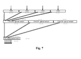
- Fig. 7 shows the diagram of optical fiber connection of the dropping unit of ROADM devices with four directions according to the embodiments of the present invention.
- the outputs of the AWGs are led out by ten MPO connectors (each MPO connector comprises an output of eight wavelengths), and the input and output ports of the 128 ⁇ 128 optical switches are respectively led out by sixteen MPO connectors (each MPO connector comprises an output of eight wavelengths).
- the input of each 128 ⁇ 128 optical switch is respectively connected with parts of outputs of the AWG in directions 1-4.
- the first eight MPO ports at the output ports of the three 128 ⁇ 128 optical switches are respectively connected with the MPO ports of the first 16-coupler/opical switch module. In this way, every eight MPO ports at the output ports of the three 128 ⁇ 128 optical switches are respectively connected with the MPO ports of the 16-coupler/opical switch modules.
- the adding unit may also employ the optical fiber connection method similar to that shown in Fig. 7 . That is, the optical fiber connection diagram of the adding unit can be obtained by reversing the arrows in Fig. 7 .
- the reconfigurable optical add/drop multiplexing device for enabling totally inresistant colorless in the present invention, based on the realization of directionless in adding and dropping and signal broadcasting function in adding and circuit direction as well as the loopback function in the circuit direction, the totally inresistant colorless in adding and dropping is realized. And the utilization of the MPO connectors simplifies the cable connections and the size of equipment and reduces the cost of the equipment.
Landscapes
- Engineering & Computer Science (AREA)
- Computer Networks & Wireless Communication (AREA)
- Signal Processing (AREA)
- Physics & Mathematics (AREA)
- Microelectronics & Electronic Packaging (AREA)
- General Physics & Mathematics (AREA)
- Optics & Photonics (AREA)
- Electromagnetism (AREA)
- Optical Communication System (AREA)
- Use Of Switch Circuits For Exchanges And Methods Of Control Of Multiplex Exchanges (AREA)
Applications Claiming Priority (2)
| Application Number | Priority Date | Filing Date | Title |
|---|---|---|---|
| CN200910158384A CN101610129B (zh) | 2009-07-09 | 2009-07-09 | 实现完全无阻的波长无关性的可重构光分插复用装置 |
| PCT/CN2009/073974 WO2011003247A1 (fr) | 2009-07-09 | 2009-09-16 | Dispositif multiplexeur optique dinsertion-extraction reconfigurable permettant dobtenir une incertitude de longueur donde sans aucune résistance |
Publications (2)
| Publication Number | Publication Date |
|---|---|
| EP2453601A1 true EP2453601A1 (fr) | 2012-05-16 |
| EP2453601A4 EP2453601A4 (fr) | 2012-12-19 |
Family
ID=41483733
Family Applications (1)
| Application Number | Title | Priority Date | Filing Date |
|---|---|---|---|
| EP09846998A Withdrawn EP2453601A4 (fr) | 2009-07-09 | 2009-09-16 | Dispositif multiplexeur optique d insertion-extraction reconfigurable permettant d obtenir une incertitude de longueur d onde sans aucune résistance |
Country Status (6)
| Country | Link |
|---|---|
| US (1) | US8861968B2 (fr) |
| EP (1) | EP2453601A4 (fr) |
| KR (1) | KR101533872B1 (fr) |
| CN (1) | CN101610129B (fr) |
| IN (1) | IN2012DN01119A (fr) |
| WO (1) | WO2011003247A1 (fr) |
Cited By (1)
| Publication number | Priority date | Publication date | Assignee | Title |
|---|---|---|---|---|
| EP2651059A1 (fr) * | 2012-04-10 | 2013-10-16 | Alcatel Lucent | Dispositif pour ajouter/glisser un élément de réseau optique |
Families Citing this family (23)
| Publication number | Priority date | Publication date | Assignee | Title |
|---|---|---|---|---|
| CN101610129B (zh) * | 2009-07-09 | 2012-10-10 | 中兴通讯股份有限公司 | 实现完全无阻的波长无关性的可重构光分插复用装置 |
| US9197354B2 (en) * | 2010-08-26 | 2015-11-24 | Ciena Corporation | Concatenated optical spectrum transmission systems and methods |
| US10461880B2 (en) | 2010-08-26 | 2019-10-29 | Ciena Corporation | Flexible grid optical spectrum transmitter, receiver, and transceiver |
| CN102130721B (zh) * | 2011-03-16 | 2014-01-08 | 烽火通信科技股份有限公司 | 自动获取可重构光分插复用器节点内部连纤关系的方法 |
| CN103023599A (zh) * | 2011-09-20 | 2013-04-03 | 武汉邮电科学研究院 | 可重构光分插复用器和可重构光分插复用方法 |
| US8989197B2 (en) * | 2012-04-02 | 2015-03-24 | Nec Laboratories America, Inc. | Reconfigurable branching unit for submarine optical communication networks |
| CN104685804B (zh) * | 2012-09-27 | 2017-06-09 | 日本电气株式会社 | 光分路/耦合设备和光分路/耦合方法 |
| US9332323B2 (en) * | 2012-10-26 | 2016-05-03 | Guohua Liu | Method and apparatus for implementing a multi-dimensional optical circuit switching fabric |
| US9332324B2 (en) | 2012-10-26 | 2016-05-03 | Guohua Liu | Method and apparatus for efficient and transparent network management and application coordination for software defined optical switched data center networks |
| ES2684771T3 (es) * | 2013-04-16 | 2018-10-04 | Huawei Technologies Co., Ltd. | Dispositivo de nodo |
| US9491526B1 (en) * | 2014-05-12 | 2016-11-08 | Google Inc. | Dynamic data center network with a mesh of wavelength selective switches |
| US9735914B2 (en) * | 2014-07-25 | 2017-08-15 | Nec Corporation | Mechanism for traffic privacy in reconfigurable add/drop multiplexer based submarine networks |
| US9654209B2 (en) * | 2015-04-08 | 2017-05-16 | Nec Corporation | Low cost secure ROADM branching unit with redundancy protection |
| CN104869480A (zh) * | 2015-04-29 | 2015-08-26 | 国网智能电网研究院 | 一种具有业务疏导功能的roadm交换节点装置和方法 |
| CN106716891B (zh) * | 2015-06-25 | 2018-11-13 | 华为技术有限公司 | 一种集成型全光交换节点 |
| WO2017092046A1 (fr) * | 2015-12-04 | 2017-06-08 | 华为技术有限公司 | Dispositif optique, et système de transmission par fibres optiques |
| US10615901B2 (en) | 2017-06-30 | 2020-04-07 | Juniper Networks, Inc. | Apparatus, systems, and methods for optical channel management |
| CN110870224B (zh) * | 2017-07-07 | 2021-05-11 | 华为技术有限公司 | 光分插复用器和光通信装置 |
| CN111596409B (zh) * | 2019-02-20 | 2022-08-30 | 阿里巴巴集团控股有限公司 | 光传输系统、调度节点、合波节点以及分波节点 |
| CN109802744B (zh) * | 2019-03-20 | 2020-09-04 | 深圳市腾讯计算机系统有限公司 | 可重构光分插复用器、光网络及光信号处理方法 |
| JP7243364B2 (ja) * | 2019-03-26 | 2023-03-22 | 日本電信電話株式会社 | 光分岐挿入装置及び光分岐挿入装置を使用した光伝送システム |
| CN113193936B (zh) * | 2021-04-28 | 2023-06-27 | 武汉光迅科技股份有限公司 | 一种支持线路id功能的多播光开关组件及其实现方法 |
| CN114545562B (zh) * | 2022-03-25 | 2023-12-26 | 阿里巴巴(中国)有限公司 | 光纤连接盒、数据处理方法、计算机存储介质 |
Family Cites Families (25)
| Publication number | Priority date | Publication date | Assignee | Title |
|---|---|---|---|---|
| US6233074B1 (en) * | 1998-05-18 | 2001-05-15 | 3Com Corporation | Ring networks utilizing wave division multiplexing |
| GB0007552D0 (en) * | 2000-03-28 | 2000-05-17 | Iltron Limited | A fully reconfigurable regenerative optical add-drop multiplexer |
| EP1379898A2 (fr) * | 2001-03-20 | 2004-01-14 | Corning Incorporated | Reseaux en anneaux dwdm proteges faisant appel a des commutateurs de selection de longueur d'onde |
| EP1378082A2 (fr) * | 2001-04-03 | 2004-01-07 | Nortel Networks Limited | Architecture de multiplexage/demultiplexage haute performance pour systemes a haute efficacite spectrale |
| CN1427571A (zh) | 2001-12-18 | 2003-07-02 | 中国科学院半导体研究所 | 光上下路分插复用器件 |
| US7027732B2 (en) * | 2002-01-18 | 2006-04-11 | Pts Corporation | WDM cross-connects for core optical networks |
| US7308197B1 (en) * | 2003-01-31 | 2007-12-11 | Ciena Corporation | Modular add/drop multiplexer including a wavelength selective switch |
| US7027680B2 (en) | 2003-02-24 | 2006-04-11 | Moog Components Group Inc. | Switch/variable optical attenuator (SVOA) |
| KR100520637B1 (ko) * | 2003-04-30 | 2005-10-13 | 삼성전자주식회사 | 파장분할다중방식 자기치유 양방향 환형 광통신망 |
| US7336901B1 (en) * | 2004-02-24 | 2008-02-26 | Avanex Corporation | Reconfigurable optical add-drop multiplexers employing optical multiplex section shared protection |
| US20050265720A1 (en) | 2004-05-28 | 2005-12-01 | Peiching Ling | Wavelength division multiplexing add/drop system employing optical switches and interleavers |
| JP4530821B2 (ja) * | 2004-08-16 | 2010-08-25 | 富士通株式会社 | 光分岐挿入装置 |
| US8190027B2 (en) * | 2006-07-12 | 2012-05-29 | Tellabs Operations, Inc. | Multifunctional and reconfigurable optical node and optical network |
| US7983560B2 (en) * | 2005-10-11 | 2011-07-19 | Dynamic Method Enterprises Limited | Modular WSS-based communications system with colorless add/drop interfaces |
| CN1870469B (zh) * | 2006-05-29 | 2010-06-09 | 浙江工业大学 | 基于声光可调谐滤波器的光学分插复用器 |
| CN101136717B (zh) * | 2006-08-28 | 2011-05-11 | 中兴通讯股份有限公司 | 实现单、多方向波长调度的可配置光分插复用装置 |
| JP4920489B2 (ja) * | 2007-05-16 | 2012-04-18 | 株式会社日立製作所 | 光分岐挿入装置 |
| CN101420286B (zh) * | 2007-10-23 | 2012-02-08 | 中兴通讯股份有限公司 | 实现灵活波长调度的可配置光分插复用装置 |
| CN101227247A (zh) * | 2007-10-30 | 2008-07-23 | 中兴通讯股份有限公司 | 实现灵活波长调度的可配置光分插复用装置 |
| US8116630B2 (en) * | 2008-12-08 | 2012-02-14 | At&T Intellectual Property I, L.P. | Methods for dynamic wavelength add/drop in a ROADM optical network |
| US8126330B2 (en) * | 2008-12-11 | 2012-02-28 | At&T Intellectual Property I, L.P. | Dynamic wavelength service over a ROADM optical network |
| US8447183B2 (en) * | 2009-04-24 | 2013-05-21 | Tellabs Operations, Inc. | Methods and apparatus for performing directionless and contentionless wavelength addition and subtraction |
| CN101610129B (zh) * | 2009-07-09 | 2012-10-10 | 中兴通讯股份有限公司 | 实现完全无阻的波长无关性的可重构光分插复用装置 |
| ES2667802T3 (es) * | 2009-07-28 | 2018-05-14 | Huawei Technologies Co., Ltd. | Aparato y procedimiento para conmutador óptico incoloro |
| US8412042B2 (en) * | 2010-04-21 | 2013-04-02 | Cisco Technology, Inc. | Innovative architecture for fully non blocking service aggregation without O-E-O conversion in a DWDM multiring interconnection node |
-
2009
- 2009-07-09 CN CN200910158384A patent/CN101610129B/zh not_active Expired - Fee Related
- 2009-09-16 US US13/383,151 patent/US8861968B2/en not_active Expired - Fee Related
- 2009-09-16 IN IN1119DEN2012 patent/IN2012DN01119A/en unknown
- 2009-09-16 WO PCT/CN2009/073974 patent/WO2011003247A1/fr not_active Ceased
- 2009-09-16 EP EP09846998A patent/EP2453601A4/fr not_active Withdrawn
- 2009-09-16 KR KR1020127003464A patent/KR101533872B1/ko not_active Expired - Fee Related
Cited By (1)
| Publication number | Priority date | Publication date | Assignee | Title |
|---|---|---|---|---|
| EP2651059A1 (fr) * | 2012-04-10 | 2013-10-16 | Alcatel Lucent | Dispositif pour ajouter/glisser un élément de réseau optique |
Also Published As
| Publication number | Publication date |
|---|---|
| WO2011003247A1 (fr) | 2011-01-13 |
| KR20120042949A (ko) | 2012-05-03 |
| US20120114332A1 (en) | 2012-05-10 |
| CN101610129B (zh) | 2012-10-10 |
| EP2453601A4 (fr) | 2012-12-19 |
| US8861968B2 (en) | 2014-10-14 |
| KR101533872B1 (ko) | 2015-07-03 |
| CN101610129A (zh) | 2009-12-23 |
| IN2012DN01119A (fr) | 2015-04-10 |
Similar Documents
| Publication | Publication Date | Title |
|---|---|---|
| US8861968B2 (en) | Reconfigurable optical add/drop multiplexing device for enabling totally inresistant colorless | |
| EP1128585A2 (fr) | Dispositif de noued et réseau de multiplexage des ondes et procédé de commutation | |
| CN101420286B (zh) | 实现灵活波长调度的可配置光分插复用装置 | |
| US20120201536A1 (en) | Method and System for Realizing Multi-Directional Reconfigurable Optical Add-Drop Multiplexing | |
| EP0488241A2 (fr) | Reseau de communication à fibre optique avec multiplexage en fréquence | |
| US20160269809A1 (en) | Optical network switching device | |
| US20170180074A1 (en) | Optical line terminal arrangement, apparatus and methods | |
| JP2011526753A (ja) | 光信号を切り換えるためのデバイス | |
| EP2311212A1 (fr) | Terminal de multiplexage par répartition en longueur d'onde à configuration et supervision automatiques de connexions de commutateur | |
| WO2016030225A1 (fr) | Multiplexage d'insertion/extraction reconfigurable dans des réseaux optiques | |
| CN104734799B (zh) | 光交换架构 | |
| CN115499728A (zh) | 一种全光交换系统及全光交换方法 | |
| CN113300804A (zh) | 光路调度装置和方法,光传输系统及数据通信系统 | |
| WO2008060007A1 (fr) | Système de connexion transversale à plusieurs degrés, procédé d'actionnement et réseau de communication optique utilisant un tel système | |
| WO2014155032A1 (fr) | Routage de signal | |
| US20130195449A1 (en) | Contentionless Add-Drop Multiplexer | |
| US20090080892A1 (en) | Network apparatus and method for guaranteeing role of optical supervisory channel | |
| US7715711B2 (en) | Wavelength selective switch design configurations for mesh light-trails | |
| US9059814B2 (en) | Modular optical patch panel | |
| WO2005060136A2 (fr) | Procede et systeme servant a communiquer un trafic optique au niveau d'un noeud | |
| US11233564B1 (en) | Method and device for migrating data traffic from an existing optical WDM transmission system to a new optical WDM transmission system | |
| Collings | Physical layer components, architectures and trends for agile photonic layer mesh networking | |
| KR100594736B1 (ko) | 파장선택 스위치 및 파장선택 방법 | |
| JP2000236303A (ja) | 光伝送システム | |
| JPS62230128A (ja) | 光通信装置 |
Legal Events
| Date | Code | Title | Description |
|---|---|---|---|
| PUAI | Public reference made under article 153(3) epc to a published international application that has entered the european phase |
Free format text: ORIGINAL CODE: 0009012 |
|
| 17P | Request for examination filed |
Effective date: 20120206 |
|
| AK | Designated contracting states |
Kind code of ref document: A1 Designated state(s): AT BE BG CH CY CZ DE DK EE ES FI FR GB GR HR HU IE IS IT LI LT LU LV MC MK MT NL NO PL PT RO SE SI SK SM TR |
|
| DAX | Request for extension of the european patent (deleted) | ||
| A4 | Supplementary search report drawn up and despatched |
Effective date: 20121119 |
|
| RIC1 | Information provided on ipc code assigned before grant |
Ipc: H04J 14/02 20060101AFI20121113BHEP |
|
| STAA | Information on the status of an ep patent application or granted ep patent |
Free format text: STATUS: EXAMINATION IS IN PROGRESS |
|
| 17Q | First examination report despatched |
Effective date: 20180103 |
|
| STAA | Information on the status of an ep patent application or granted ep patent |
Free format text: STATUS: THE APPLICATION IS DEEMED TO BE WITHDRAWN |
|
| 18D | Application deemed to be withdrawn |
Effective date: 20181016 |