EP2454521B1 - Luminaire électrique - Google Patents
Luminaire électrique Download PDFInfo
- Publication number
- EP2454521B1 EP2454521B1 EP10743001.9A EP10743001A EP2454521B1 EP 2454521 B1 EP2454521 B1 EP 2454521B1 EP 10743001 A EP10743001 A EP 10743001A EP 2454521 B1 EP2454521 B1 EP 2454521B1
- Authority
- EP
- European Patent Office
- Prior art keywords
- light
- light source
- lamp
- accordance
- electric lamp
- Prior art date
- Legal status (The legal status is an assumption and is not a legal conclusion. Google has not performed a legal analysis and makes no representation as to the accuracy of the status listed.)
- Not-in-force
Links
Images
Classifications
-
- F—MECHANICAL ENGINEERING; LIGHTING; HEATING; WEAPONS; BLASTING
- F21—LIGHTING
- F21S—NON-PORTABLE LIGHTING DEVICES; SYSTEMS THEREOF; VEHICLE LIGHTING DEVICES SPECIALLY ADAPTED FOR VEHICLE EXTERIORS
- F21S6/00—Lighting devices intended to be free-standing
- F21S6/001—Lighting devices intended to be free-standing candle-shaped
-
- F—MECHANICAL ENGINEERING; LIGHTING; HEATING; WEAPONS; BLASTING
- F21—LIGHTING
- F21W—INDEXING SCHEME ASSOCIATED WITH SUBCLASSES F21K, F21L, F21S and F21V, RELATING TO USES OR APPLICATIONS OF LIGHTING DEVICES OR SYSTEMS
- F21W2121/00—Use or application of lighting devices or systems for decorative purposes, not provided for in codes F21W2102/00 – F21W2107/00
- F21W2121/04—Use or application of lighting devices or systems for decorative purposes, not provided for in codes F21W2102/00 – F21W2107/00 for Christmas trees
-
- F—MECHANICAL ENGINEERING; LIGHTING; HEATING; WEAPONS; BLASTING
- F21—LIGHTING
- F21Y—INDEXING SCHEME ASSOCIATED WITH SUBCLASSES F21K, F21L, F21S and F21V, RELATING TO THE FORM OR THE KIND OF THE LIGHT SOURCES OR OF THE COLOUR OF THE LIGHT EMITTED
- F21Y2115/00—Light-generating elements of semiconductor light sources
- F21Y2115/10—Light-emitting diodes [LED]
Definitions
- the invention relates to an electric lamp, comprising at least one light fixture and at least one, arranged at one end of the light fixture, the light source, wherein the power supply for the light source in the interior, is provided from the light source remote from the end of the hollow shaped lamp holder and the light source in Inside the lamp holder is arranged in a light source holder and at the light exiting lamp holder end, a light material consisting of a transparent material, such as glass and / or plastic, is arranged.
- Such a lamp is from the DE 20 2007 003 615 U1 known.
- These battery-powered lighting arrangements in the manner of a candle are intended in particular as a replacement for Christmas tree candles.
- light emitting diodes so-called LEDs, are used.
- Another electric candle light is from the DE 197 34 345 A1 known, in which a light emitting diode is used as a lighting fixture.
- a portable, battery-powered effect light in rod format is from the DE 201 16 113 U1 known.
- a candle-shaped lamp which has a flame body made of glass or plastic. In this flame body protrudes the bulb.
- the object of the invention is od a lamp of the type cited for a room or a hall. Like. To create, which gives the real impression of a burning candle.
- the invention is characterized in that the light attachment on the surface facing the light source has a central bore, preferably a blind bore, and that over the light source, a preferably elongated, light guide is arranged, which projects into the central bore of the light attachment.
- the light source is at least one light-emitting diode, preferably a high-power light-emitting diode.
- the light source consists of a plurality of light emitting diodes, optionally with different Color temperature and / or color.
- the light source consists of four LEDs, two LEDs having a color temperature of 3,000 K, a LED of 5,400 K, and a colored LED. With such a light source improved color reproduction is achieved with a high efficiency. Furthermore, a more uniform light from different LED production batches is achieved.
- the light source is arranged at a distance from the lamp holder end. As a result, the light source never appears directly to the viewer, so that the visual impression of a candle is given.
- the light source should thus be arranged below the light attachment.
- the light source holder provided in the lamp holder is designed as a heat sink.
- the problem of heat dissipation inevitably exists. Due to the intelligent construction of the luminaire according to the invention, in particular the design of the light source holder as a heat sink, the corresponding heat dissipation from the hot spot zone is ensured. A high lifetime of the electronic components achieved thereby is the positive effect.
- a very special feature of the invention determines the execution and / or shaping of the closed end of the blind hole in the light tower with the execution and / or shaping of the projecting into the blind hole head end of the light guide, the light distribution, wherein the light exit surface of the light guide and the light entrance surface of the blind bore form a lens system.
- the appropriate design determines the physiological perception of light, ie the ambience created in the room.
- the end of the blind bore is concave, convex, prismatic, hemispherical and / or frosted.
- the visual visual impression can be determined with it.
- the head end of the light guide is concave, convex, prismatic, hemispherical and / or frosted. In conjunction with the execution of the blind bore thus a corresponding perception of light can be caused.
- the light attachment is made of a polyurethane-based or acrylic-based plastic.
- a polyurethane-based or acrylic-based plastic Such materials have proven themselves in practice, since they are easy to work on the one hand and on the other hand are low care.
- the light attachment has an individual shape, in particular a crystal, a light bulb or a candle head.
- the shape of the light tower is reserved for the creative designers of the modern age.
- the light attachment is attached via a plug, adhesive or screw on the lamp holder.
- a plug, adhesive or screw on the lamp holder Such simple connection variants increase the ease of installation and have proven themselves very well.
- an electronics in particular an electronic control system is provided inside the lamp holder between the power supply and the light source, wherein a mounting plate for the electronics is provided as a heat sink.
- an electronic control system is used.
- the mounting plate is used for heat dissipation.
- a long service life of the control electronics is given.
- the electronics in particular the control electronics, a temperature or light sensor, which detects the temperature at the hot spot location of the light emitting diode or a light spot. This makes it possible to gain control over the temperature prevailing in operation near the light source, whereby the life of the light source can be extended enormously.
- a uniform brightness constancy and / or color constancy is achieved by the detection of one or more representative points of light.
- the electronics in particular the control electronics, a current regulator, in particular a microprocessor for dimming and / or control functions, wherein optionally the current regulator is controlled by the microprocessor from the temperature or light sensor or via an external control.
- a current regulator in particular a microprocessor for dimming and / or control functions
- the microprocessor is used to decode external switching, control or function commands.
- the microprocessor is used to decode external switching, control or function commands.
- a flickering of the light can be achieved.
- a dimming with predetermined variable color changes is possible.
- the light is cast for use outdoors.
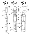
- the Fig. 1 and 2 shows an electric lamp in the design of a candle light, which consists of a lamp holder 1 and a, arranged at one end of the lamp holder 1, the light source 2.
- the light source 2 is a light emitting diode, preferably a high power light emitting diode.
- the light source 2 could also consist of several light emitting diodes, optionally with different color temperature.
- the light source could consist of four LEDs, two LEDs having a color temperature of 3,000 K, a LED of 5,400 K, and a colored LED.
- the light source 2 is arranged at a distance from the lamp holder end.
- the light source 2 is thus not directly visible and is located below the light attachment.
- the power supply for the light source 2 is provided in the interior, from the light source 2 facing away from the end of the hollow shaped lamp holder 1 and via a cable 3 or a line.
- the light source 2 is arranged inside the lamp holder 1 in a light source holder 4.
- a of a transparent material, such as glass and / or plastic existing, light attachment 5 is arranged.
- the light source holder 4 on its outer side a groove or groove 6. As a result, the cable 3 can be guided between the light source holder 4 and the inside of the lamp holder 1.
- the light cap 5 has on the light source 2 facing surface a central bore, preferably a blind bore 7, on.
- a central bore preferably a blind bore 7
- a light guide 8 is arranged, which projects into the central blind bore 7 of the light attachment 5.
- the light distribution is determined.
- the light exit surface from the light guide 8 and the light entry surface of the blind bore 7 form a quasi-lens system.
- the end 9 of the blind bore 7 may be concave, convex, prismatic, hemispherical and / or frosted.
- the head end 10 of the light guide 8 may be concave, convex, prismatic, hemispherical and / or frosted.
- the corresponding design determines the physiological perception of light, ie the ambience created in the room.
- the Lichtaufsatz 5 itself may consist of a plastic based on polyurethane or acrylic. Of course, other materials, such as glass, especially ground glass, conceivable. That other forms of the Lichtaufsatzes 5 are conceivable, will be shown later.
- the light cap 5 may be formed such that an additional light distribution and optionally a color correction are achieved, whereby the light guide 8 is not perceived. Attached, the light attachment 5 can be on the light source holder 4 or at the end of the lamp holder 1 via a plug, adhesive or screw connection.
- the LED used as the light source 2 is arranged on the light source holder 4 or fixed, for example, with an adhesive connection.
- the elongate, substantially cylindrical optical fiber 8 is disposed directly over the LED and could have a ring or sleeve at the LED facing end. About this ring or the sleeve of the light guide 8 is held defined with the light attachment 5 and the arrangement in the light fixture 1 attached.
- an electronics in particular an electronic control unit 11 in the form of a board, is provided, which is arranged on a mounting plate 12.
- the mounting plate 12 serves as a heat sink. For easy mounting and mounting of the mounting plate 12, this can be mounted by means of a plug-in adhesive connection in the light source holder 4.
- the light source holder 4 provided in the light fixture 1 is likewise designed as a heat sink. An optimal heat dissipation is guaranteed.
- control electronics 11 has a temperature sensor which detects the temperature at the hot spot location of the light emitting diode. This provides control over the temperature of operation near the light source during operation. The power could thus be reduced via the control electronics 11. In particular, this may be the case when the control electronics 11 comprises a current regulator 13 with dimming function and the current regulator is controlled by the temperature sensor.
- the electronics in particular the control electronics 11, may also have a light sensor which detects one or more representative points of light, whereby a uniform brightness constancy and / or color constancy can be achieved.
- the control electronics 11, in particular the current controller 13, may include a microprocessor for dimming and / or control functions, wherein the current controller 13 is controlled by the microprocessor from the temperature or light sensor or via an external control.
- the microprocessor is preferably for processing external switching, control or function commands.
- the light cap 5 has the shape of a light bulb. Also in this case, the light distribution and Thus, the visual perception of the light by a viewer through the execution of the blind hole 7 in the light tower 5 in conjunction with the projecting into the interior light guide 8 determines.
Landscapes
- Engineering & Computer Science (AREA)
- General Engineering & Computer Science (AREA)
- Non-Portable Lighting Devices Or Systems Thereof (AREA)
- Arrangement Of Elements, Cooling, Sealing, Or The Like Of Lighting Devices (AREA)
Claims (15)
- Lampe électrique composé d'au moins un support et d'une source lumineuse fixée sur le bout du support, l'alimentation en énergie de la source lumineuse étant prévue à l'intérieur du bout se trouvant à l'opposé de la source lumineuse, le support étant creux et la source lumineuse se trouvant à l'intérieur du support. Au bout d'émission de lumière il y a une pièce en une matière transparente telle que verre et/ou plastique, laquelle est caractérisée par le fait que la pièce (5) possède sur sa face donnant sur la source lumineuse (2) un alésage centrique, de préférence un alésage borgne (7), et qu'un conducteur optique (8) de préférence de forme longitudinale est disposé au dessus de la source lumineuse (2), lequel avance dans l'alésage centrique de la pièce (5).
- Lampe électrique selon la revendication 1, caractérisée par le fait que la source lumineuse (2) est une diode lumineuse minimum, et une diode de puissance élevée de préférence.
- Lampe électrique selon la revendication 1 ou 2, caractérisée par le fait que la source lumineuse (2) se compose de plusieurs diodes lumineuses de différentes couleurs le cas échéant, et/ou de différentes températures de couleur.
- Lampe électrique selon l'une des revendications 1 à 3, caractérisée par le fait que la source lumineuse (2) est disposée à une certaine distance du support de la lampe.
- Lampe électrique selon l'une des revendications 1 à 4, caractérisée par le fait que le support de la source lumineuse (4) prévue dans le support de la lampe (1) est un dissipateur thermique.
- Lampe électrique selon l'une des revendications 1 à 3, caractérisée par le fait que l'exécution et/ou la forme du bout fermé (9) de l'alésage borgne (7) dans la pièce lumineuse (5), conjointement avec l'exécution et/ou la forme de la tête (10) du conducteur optique (8) qui avance dans l'alésage borgne (7) détermine la répartition de la lumière. La face d'émission lumineuse sur le conducteur optique (8) et la face d'immission de l'alésage borgne (7) formant un système de lentille.
- Lampe électrique selon la revendication 6, caractérisée par le fait que le bout (9) de l'alésage borgne (7) est de forme concave, convexe, prismatique, hémisphérique et/ou mate.
- Lampe électrique selon la revendication 6, caractérisée par le fait que le bout (9) du conducteur optique (8) est de forme concave, convexe, prismatique, hémisphérique et/ou mate.
- Lampe électrique selon au moins l'une des revendications 1 à 8, caractérisée par le fait que la pièce lumineuse (5) est en verre ou en un autre plastique sur la base de polyuréthane ou d'acryl.
- Lampe électrique selon au moins l'une des revendications 1 à 9, caractérisée par le fait que la pièce lumineuse (5) possède une forme individuelle, notamment celle d'un cristal, d'une ampoule ou d'une bougie ampoule.
- Lampe électrique selon au moins l'une des revendications 1 à 10, caractérisée par le fait que la pièce lumineuse (5) est connectée au support de la lampe (1) par une fiche de raccordement ou par un raccord collé ou vissé.
- Lampe électrique selon au moins l'une des revendications 1 à 11, caractérisée par le fait qu'à l'intérieur du support de la lampe (1) entre l'alimentation en énergie et la source lumineuse (2), un unité électronique et plus particulièrement une unité de commande électronique (11) est prévue, la partie électronique étant refroidie par une plaque de montage (12).
- Lampe électrique selon au moins l'une des revendications 1 à 12, caractérisée par le fait que l'unité électronique et plus particulièrement l'unité de commande électronique (11) est dotée d'un capteur de température ou d'un capteur de lumière qui saisit la température au hot spot de la diode lumineuse ou bien un point lumineux.
- Lampe électrique selon au moins l'une des revendications 1 à 13, caractérisée par le fait que la partie électronique, notamment l'unité de commande électronique (11) possède un rhéostat-régulateur d'intensité du courant (13) et plus particulièrement un microprocesseur réglant les fonctions de gradation et/ou de commande, le rhéostat-régulateur d'intensité (13) étant adressé via le microprocesseur du capteur de température ou de lumière, ou bien via une autre excitation extérieure.
- Lampe électrique selon au moins l'une des revendications 1 à 13, caractérisée par le fait que pour l'utilisation à l'extérieur, la lampe est emboîtée.
Applications Claiming Priority (2)
| Application Number | Priority Date | Filing Date | Title |
|---|---|---|---|
| AT0110509A AT508262B1 (de) | 2009-07-14 | 2009-07-14 | Elektrische leuchte |
| PCT/AT2010/000252 WO2011006178A1 (fr) | 2009-07-14 | 2010-07-09 | Luminaire électrique |
Publications (2)
| Publication Number | Publication Date |
|---|---|
| EP2454521A1 EP2454521A1 (fr) | 2012-05-23 |
| EP2454521B1 true EP2454521B1 (fr) | 2013-05-29 |
Family
ID=43033168
Family Applications (1)
| Application Number | Title | Priority Date | Filing Date |
|---|---|---|---|
| EP10743001.9A Not-in-force EP2454521B1 (fr) | 2009-07-14 | 2010-07-09 | Luminaire électrique |
Country Status (3)
| Country | Link |
|---|---|
| EP (1) | EP2454521B1 (fr) |
| AT (1) | AT508262B1 (fr) |
| WO (1) | WO2011006178A1 (fr) |
Cited By (5)
| Publication number | Priority date | Publication date | Assignee | Title |
|---|---|---|---|---|
| US9574748B2 (en) | 2013-07-30 | 2017-02-21 | Shenzhen Yameite Technology Co. Ltd. | Illumination devices |
| US9909728B2 (en) | 2013-07-30 | 2018-03-06 | Shenzhen Yameite Technology Co. Ltd. | Illumination devices |
| US9915402B2 (en) | 2013-07-30 | 2018-03-13 | Shenzhen Yameite Technology Co. Ltd. | Illumination devices |
| US10948146B2 (en) | 2010-06-28 | 2021-03-16 | L&L Candle Company, Llc | Electronic lighting device and method for manufacturing same |
| US10976020B2 (en) | 2008-09-30 | 2021-04-13 | L&L Candle Company, Llc | Kinetic flame device |
Families Citing this family (2)
| Publication number | Priority date | Publication date | Assignee | Title |
|---|---|---|---|---|
| FR3036163A1 (fr) * | 2014-10-27 | 2016-11-18 | Jacques Klotz | Bougie electrique |
| EP4105548A1 (fr) * | 2021-06-17 | 2022-12-21 | Sirius Home A/S | Bougie artificielle |
Family Cites Families (9)
| Publication number | Priority date | Publication date | Assignee | Title |
|---|---|---|---|---|
| DE19734345A1 (de) | 1997-08-08 | 1999-02-18 | Eckhard Gerke | Elektrische Kerzenleuchte |
| DE29922848U1 (de) | 1999-12-27 | 2000-05-04 | Hückmann, Winfried, 97618 Niederlauer | Elektronisch gesteuerte Flackerkerze |
| US20030012016A1 (en) * | 2001-07-16 | 2003-01-16 | Chun-Teng Lee | Protective tube having light convergent flash lamp |
| DE20116113U1 (de) | 2001-10-01 | 2002-01-10 | Schulte, Wolfgang, 40229 Düsseldorf | Effekt-Leuchte |
| DE202004003595U1 (de) | 2004-03-09 | 2004-05-13 | Zweibrüder Optoelectronics GmbH | Kerzenförmige Lampe |
| US20070223216A1 (en) * | 2006-03-27 | 2007-09-27 | The Lamson & Sessions Co. | Artificial candle |
| DE202007003615U1 (de) | 2006-10-18 | 2007-05-24 | Kompled Gmbh & Co. Kg | Batteriebetriebene Leuchtenanordnung, insbesondere nach Art einer Kerze |
| DE202007000214U1 (de) | 2007-01-08 | 2007-04-05 | Tsai, Sam | Elektrische Kerze mit Mikrosteuervorrichtung |
| DE202008005398U1 (de) | 2008-04-18 | 2008-09-04 | Krinner Innovation Gmbh | LED-Leuchtmittel |
-
2009
- 2009-07-14 AT AT0110509A patent/AT508262B1/de not_active IP Right Cessation
-
2010
- 2010-07-09 EP EP10743001.9A patent/EP2454521B1/fr not_active Not-in-force
- 2010-07-09 WO PCT/AT2010/000252 patent/WO2011006178A1/fr not_active Ceased
Cited By (17)
| Publication number | Priority date | Publication date | Assignee | Title |
|---|---|---|---|---|
| US11105481B2 (en) | 2008-09-30 | 2021-08-31 | L&L Candle Company, Llc | Kinetic flame device |
| US12359784B2 (en) | 2008-09-30 | 2025-07-15 | L&L Candle Company, Llc | Kinetic flame device |
| US11885467B2 (en) | 2008-09-30 | 2024-01-30 | L&L Candle Company, Llc | Kinetic flame device |
| US10976020B2 (en) | 2008-09-30 | 2021-04-13 | L&L Candle Company, Llc | Kinetic flame device |
| US10989381B2 (en) | 2008-09-30 | 2021-04-27 | L&L Candle Company, Llc | Kinetic flame device |
| US11828426B2 (en) | 2010-06-28 | 2023-11-28 | L&L Candle Company, Llc | Electronic lighting device and method for manufacturing same |
| US11105480B2 (en) | 2010-06-28 | 2021-08-31 | L&L Candle Company, Llc | Electronic lighting device and method for manufacturing same |
| US10948146B2 (en) | 2010-06-28 | 2021-03-16 | L&L Candle Company, Llc | Electronic lighting device and method for manufacturing same |
| US10969074B2 (en) | 2010-06-28 | 2021-04-06 | L&L Candle Company, Llc | Electronic lighting device and method for manufacturing same |
| US10578281B2 (en) | 2013-07-30 | 2020-03-03 | Haisong Dong | Illumination devices |
| US11085612B2 (en) | 2013-07-30 | 2021-08-10 | Haisong Dong | Illumination devices |
| US9574748B2 (en) | 2013-07-30 | 2017-02-21 | Shenzhen Yameite Technology Co. Ltd. | Illumination devices |
| US11396997B2 (en) | 2013-07-30 | 2022-07-26 | Haisong Dong | Illumination devices |
| US11608963B2 (en) | 2013-07-30 | 2023-03-21 | Haisong Dong | Illumination devices |
| US10082274B2 (en) | 2013-07-30 | 2018-09-25 | Haisong Dong | Illumination devices |
| US9915402B2 (en) | 2013-07-30 | 2018-03-13 | Shenzhen Yameite Technology Co. Ltd. | Illumination devices |
| US9909728B2 (en) | 2013-07-30 | 2018-03-06 | Shenzhen Yameite Technology Co. Ltd. | Illumination devices |
Also Published As
| Publication number | Publication date |
|---|---|
| AT508262A4 (de) | 2010-12-15 |
| AT508262B1 (de) | 2010-12-15 |
| WO2011006178A1 (fr) | 2011-01-20 |
| EP2454521A1 (fr) | 2012-05-23 |
Similar Documents
| Publication | Publication Date | Title |
|---|---|---|
| AT508262B1 (de) | Elektrische leuchte | |
| EP2110598B1 (fr) | Dispositif d'éclairage | |
| EP2893775B1 (fr) | Luminaire | |
| DE102009051763A1 (de) | Beleuchtungsvorrichtung mit einem Kolben | |
| DE20016549U1 (de) | Zier-Solarlampenbaueinheit | |
| EP1006311A2 (fr) | Lampe du type lampe de signalisation et/ou d'orientation | |
| WO2010031810A1 (fr) | Lampe comportant au moins une diode électroluminescente | |
| AT506384B1 (de) | Beleuchtungskörper | |
| EP2827056A1 (fr) | Lampe à diodes électroluminescentes à vocation générale | |
| EP2273185B1 (fr) | Eléments d'éclairage à DEL dotés d'un élément de guidage de la lumière | |
| DE102007058173A1 (de) | Leuchte mit hochstehendem Lichtleiter | |
| EP2564116B1 (fr) | Lampe à del comme substitut d'ampoule à incandescence | |
| DE112013002008T5 (de) | Beleuchtungslichtquelle | |
| DE112013006624T5 (de) | Beleuchtungsvorrichtung | |
| EP2529259B1 (fr) | Appareil d'éclairage comprenant une source de lumière et un diffuseur optique | |
| EP2483593B1 (fr) | Lampe avec substrate variable comme base pour la source lumineux | |
| DE202010010263U1 (de) | Beleuchtungseinrichtung, insbesondere für einen Außenbereich | |
| DE202009014794U1 (de) | Beleuchtungseinrichtung und Lampe für diese | |
| EP2051004B1 (fr) | Eclairage, notamment pour des vitrines ou des vitrines d'exposition | |
| DE20019874U1 (de) | Lampe | |
| DE202010004760U1 (de) | LED-Pendelleuchte | |
| CH701962B1 (de) | Beleuchtungseinrichtung und Lampe für diese. | |
| DE102008047356A1 (de) | Leuchtmittel mit Leuchtdioden sowie Leuchte dafür | |
| DE102014104882A1 (de) | Elektrische Leuchte | |
| DE202013001733U1 (de) | Leucht-Soffitte-LED mit Federkontakt |
Legal Events
| Date | Code | Title | Description |
|---|---|---|---|
| PUAI | Public reference made under article 153(3) epc to a published international application that has entered the european phase |
Free format text: ORIGINAL CODE: 0009012 |
|
| 17P | Request for examination filed |
Effective date: 20120213 |
|
| AK | Designated contracting states |
Kind code of ref document: A1 Designated state(s): AL AT BE BG CH CY CZ DE DK EE ES FI FR GB GR HR HU IE IS IT LI LT LU LV MC MK MT NL NO PL PT RO SE SI SK SM TR |
|
| DAX | Request for extension of the european patent (deleted) | ||
| REG | Reference to a national code |
Ref country code: DE Ref legal event code: R079 Ref document number: 502010003483 Country of ref document: DE Free format text: PREVIOUS MAIN CLASS: F21S0004000000 Ipc: F21S0006000000 |
|
| GRAP | Despatch of communication of intention to grant a patent |
Free format text: ORIGINAL CODE: EPIDOSNIGR1 |
|
| RIC1 | Information provided on ipc code assigned before grant |
Ipc: F21S 6/00 20060101AFI20121126BHEP |
|
| GRAS | Grant fee paid |
Free format text: ORIGINAL CODE: EPIDOSNIGR3 |
|
| GRAA | (expected) grant |
Free format text: ORIGINAL CODE: 0009210 |
|
| AK | Designated contracting states |
Kind code of ref document: B1 Designated state(s): AL AT BE BG CH CY CZ DE DK EE ES FI FR GB GR HR HU IE IS IT LI LT LU LV MC MK MT NL NO PL PT RO SE SI SK SM TR |
|
| REG | Reference to a national code |
Ref country code: GB Ref legal event code: FG4D Free format text: NOT ENGLISH |
|
| REG | Reference to a national code |
Ref country code: CH Ref legal event code: EP |
|
| REG | Reference to a national code |
Ref country code: AT Ref legal event code: REF Ref document number: 614647 Country of ref document: AT Kind code of ref document: T Effective date: 20130615 |
|
| REG | Reference to a national code |
Ref country code: IE Ref legal event code: FG4D Free format text: LANGUAGE OF EP DOCUMENT: GERMAN |
|
| REG | Reference to a national code |
Ref country code: DE Ref legal event code: R096 Ref document number: 502010003483 Country of ref document: DE Effective date: 20130725 |
|
| REG | Reference to a national code |
Ref country code: LT Ref legal event code: MG4D |
|
| PG25 | Lapsed in a contracting state [announced via postgrant information from national office to epo] |
Ref country code: SE Free format text: LAPSE BECAUSE OF FAILURE TO SUBMIT A TRANSLATION OF THE DESCRIPTION OR TO PAY THE FEE WITHIN THE PRESCRIBED TIME-LIMIT Effective date: 20130529 Ref country code: PT Free format text: LAPSE BECAUSE OF FAILURE TO SUBMIT A TRANSLATION OF THE DESCRIPTION OR TO PAY THE FEE WITHIN THE PRESCRIBED TIME-LIMIT Effective date: 20130930 Ref country code: LT Free format text: LAPSE BECAUSE OF FAILURE TO SUBMIT A TRANSLATION OF THE DESCRIPTION OR TO PAY THE FEE WITHIN THE PRESCRIBED TIME-LIMIT Effective date: 20130529 Ref country code: IS Free format text: LAPSE BECAUSE OF FAILURE TO SUBMIT A TRANSLATION OF THE DESCRIPTION OR TO PAY THE FEE WITHIN THE PRESCRIBED TIME-LIMIT Effective date: 20130929 Ref country code: SI Free format text: LAPSE BECAUSE OF FAILURE TO SUBMIT A TRANSLATION OF THE DESCRIPTION OR TO PAY THE FEE WITHIN THE PRESCRIBED TIME-LIMIT Effective date: 20130529 Ref country code: NO Free format text: LAPSE BECAUSE OF FAILURE TO SUBMIT A TRANSLATION OF THE DESCRIPTION OR TO PAY THE FEE WITHIN THE PRESCRIBED TIME-LIMIT Effective date: 20130829 Ref country code: ES Free format text: LAPSE BECAUSE OF FAILURE TO SUBMIT A TRANSLATION OF THE DESCRIPTION OR TO PAY THE FEE WITHIN THE PRESCRIBED TIME-LIMIT Effective date: 20130909 Ref country code: GR Free format text: LAPSE BECAUSE OF FAILURE TO SUBMIT A TRANSLATION OF THE DESCRIPTION OR TO PAY THE FEE WITHIN THE PRESCRIBED TIME-LIMIT Effective date: 20130830 Ref country code: FI Free format text: LAPSE BECAUSE OF FAILURE TO SUBMIT A TRANSLATION OF THE DESCRIPTION OR TO PAY THE FEE WITHIN THE PRESCRIBED TIME-LIMIT Effective date: 20130529 |
|
| REG | Reference to a national code |
Ref country code: NL Ref legal event code: VDEP Effective date: 20130529 |
|
| PG25 | Lapsed in a contracting state [announced via postgrant information from national office to epo] |
Ref country code: PL Free format text: LAPSE BECAUSE OF FAILURE TO SUBMIT A TRANSLATION OF THE DESCRIPTION OR TO PAY THE FEE WITHIN THE PRESCRIBED TIME-LIMIT Effective date: 20130529 Ref country code: BG Free format text: LAPSE BECAUSE OF FAILURE TO SUBMIT A TRANSLATION OF THE DESCRIPTION OR TO PAY THE FEE WITHIN THE PRESCRIBED TIME-LIMIT Effective date: 20130829 Ref country code: HR Free format text: LAPSE BECAUSE OF FAILURE TO SUBMIT A TRANSLATION OF THE DESCRIPTION OR TO PAY THE FEE WITHIN THE PRESCRIBED TIME-LIMIT Effective date: 20130529 |
|
| PGFP | Annual fee paid to national office [announced via postgrant information from national office to epo] |
Ref country code: FR Payment date: 20130722 Year of fee payment: 4 |
|
| PG25 | Lapsed in a contracting state [announced via postgrant information from national office to epo] |
Ref country code: LV Free format text: LAPSE BECAUSE OF FAILURE TO SUBMIT A TRANSLATION OF THE DESCRIPTION OR TO PAY THE FEE WITHIN THE PRESCRIBED TIME-LIMIT Effective date: 20130529 |
|
| BERE | Be: lapsed |
Owner name: PODPOD DESIGN PODGORSCHEK & PODGORSCHEK LIGHTING Effective date: 20130731 Owner name: SCHRUTEK, ELMAR Effective date: 20130731 |
|
| PG25 | Lapsed in a contracting state [announced via postgrant information from national office to epo] |
Ref country code: EE Free format text: LAPSE BECAUSE OF FAILURE TO SUBMIT A TRANSLATION OF THE DESCRIPTION OR TO PAY THE FEE WITHIN THE PRESCRIBED TIME-LIMIT Effective date: 20130529 Ref country code: SK Free format text: LAPSE BECAUSE OF FAILURE TO SUBMIT A TRANSLATION OF THE DESCRIPTION OR TO PAY THE FEE WITHIN THE PRESCRIBED TIME-LIMIT Effective date: 20130529 Ref country code: DK Free format text: LAPSE BECAUSE OF FAILURE TO SUBMIT A TRANSLATION OF THE DESCRIPTION OR TO PAY THE FEE WITHIN THE PRESCRIBED TIME-LIMIT Effective date: 20130529 Ref country code: CZ Free format text: LAPSE BECAUSE OF FAILURE TO SUBMIT A TRANSLATION OF THE DESCRIPTION OR TO PAY THE FEE WITHIN THE PRESCRIBED TIME-LIMIT Effective date: 20130529 |
|
| PG25 | Lapsed in a contracting state [announced via postgrant information from national office to epo] |
Ref country code: IT Free format text: LAPSE BECAUSE OF FAILURE TO SUBMIT A TRANSLATION OF THE DESCRIPTION OR TO PAY THE FEE WITHIN THE PRESCRIBED TIME-LIMIT Effective date: 20130529 Ref country code: RO Free format text: LAPSE BECAUSE OF FAILURE TO SUBMIT A TRANSLATION OF THE DESCRIPTION OR TO PAY THE FEE WITHIN THE PRESCRIBED TIME-LIMIT Effective date: 20130529 Ref country code: MC Free format text: LAPSE BECAUSE OF FAILURE TO SUBMIT A TRANSLATION OF THE DESCRIPTION OR TO PAY THE FEE WITHIN THE PRESCRIBED TIME-LIMIT Effective date: 20130529 Ref country code: NL Free format text: LAPSE BECAUSE OF FAILURE TO SUBMIT A TRANSLATION OF THE DESCRIPTION OR TO PAY THE FEE WITHIN THE PRESCRIBED TIME-LIMIT Effective date: 20130529 |
|
| PLBE | No opposition filed within time limit |
Free format text: ORIGINAL CODE: 0009261 |
|
| STAA | Information on the status of an ep patent application or granted ep patent |
Free format text: STATUS: NO OPPOSITION FILED WITHIN TIME LIMIT |
|
| REG | Reference to a national code |
Ref country code: IE Ref legal event code: MM4A |
|
| PG25 | Lapsed in a contracting state [announced via postgrant information from national office to epo] |
Ref country code: BE Free format text: LAPSE BECAUSE OF NON-PAYMENT OF DUE FEES Effective date: 20130731 |
|
| 26N | No opposition filed |
Effective date: 20140303 |
|
| REG | Reference to a national code |
Ref country code: DE Ref legal event code: R097 Ref document number: 502010003483 Country of ref document: DE Effective date: 20140303 |
|
| PG25 | Lapsed in a contracting state [announced via postgrant information from national office to epo] |
Ref country code: IE Free format text: LAPSE BECAUSE OF NON-PAYMENT OF DUE FEES Effective date: 20130709 |
|
| REG | Reference to a national code |
Ref country code: CH Ref legal event code: PL |
|
| GBPC | Gb: european patent ceased through non-payment of renewal fee |
Effective date: 20140709 |
|
| REG | Reference to a national code |
Ref country code: FR Ref legal event code: ST Effective date: 20150331 |
|
| PG25 | Lapsed in a contracting state [announced via postgrant information from national office to epo] |
Ref country code: CH Free format text: LAPSE BECAUSE OF NON-PAYMENT OF DUE FEES Effective date: 20140731 Ref country code: LI Free format text: LAPSE BECAUSE OF NON-PAYMENT OF DUE FEES Effective date: 20140731 |
|
| PG25 | Lapsed in a contracting state [announced via postgrant information from national office to epo] |
Ref country code: FR Free format text: LAPSE BECAUSE OF NON-PAYMENT OF DUE FEES Effective date: 20140731 Ref country code: SM Free format text: LAPSE BECAUSE OF FAILURE TO SUBMIT A TRANSLATION OF THE DESCRIPTION OR TO PAY THE FEE WITHIN THE PRESCRIBED TIME-LIMIT Effective date: 20130529 Ref country code: GB Free format text: LAPSE BECAUSE OF NON-PAYMENT OF DUE FEES Effective date: 20140709 |
|
| PG25 | Lapsed in a contracting state [announced via postgrant information from national office to epo] |
Ref country code: CY Free format text: LAPSE BECAUSE OF FAILURE TO SUBMIT A TRANSLATION OF THE DESCRIPTION OR TO PAY THE FEE WITHIN THE PRESCRIBED TIME-LIMIT Effective date: 20130529 Ref country code: MT Free format text: LAPSE BECAUSE OF FAILURE TO SUBMIT A TRANSLATION OF THE DESCRIPTION OR TO PAY THE FEE WITHIN THE PRESCRIBED TIME-LIMIT Effective date: 20130529 Ref country code: TR Free format text: LAPSE BECAUSE OF FAILURE TO SUBMIT A TRANSLATION OF THE DESCRIPTION OR TO PAY THE FEE WITHIN THE PRESCRIBED TIME-LIMIT Effective date: 20130529 |
|
| PG25 | Lapsed in a contracting state [announced via postgrant information from national office to epo] |
Ref country code: HU Free format text: LAPSE BECAUSE OF FAILURE TO SUBMIT A TRANSLATION OF THE DESCRIPTION OR TO PAY THE FEE WITHIN THE PRESCRIBED TIME-LIMIT; INVALID AB INITIO Effective date: 20100709 Ref country code: LU Free format text: LAPSE BECAUSE OF NON-PAYMENT OF DUE FEES Effective date: 20130709 Ref country code: MK Free format text: LAPSE BECAUSE OF FAILURE TO SUBMIT A TRANSLATION OF THE DESCRIPTION OR TO PAY THE FEE WITHIN THE PRESCRIBED TIME-LIMIT Effective date: 20130529 |
|
| PGFP | Annual fee paid to national office [announced via postgrant information from national office to epo] |
Ref country code: DE Payment date: 20170731 Year of fee payment: 8 |
|
| PGFP | Annual fee paid to national office [announced via postgrant information from national office to epo] |
Ref country code: AT Payment date: 20170726 Year of fee payment: 8 |
|
| PG25 | Lapsed in a contracting state [announced via postgrant information from national office to epo] |
Ref country code: AL Free format text: LAPSE BECAUSE OF FAILURE TO SUBMIT A TRANSLATION OF THE DESCRIPTION OR TO PAY THE FEE WITHIN THE PRESCRIBED TIME-LIMIT Effective date: 20130529 |
|
| REG | Reference to a national code |
Ref country code: DE Ref legal event code: R119 Ref document number: 502010003483 Country of ref document: DE |
|
| REG | Reference to a national code |
Ref country code: AT Ref legal event code: MM01 Ref document number: 614647 Country of ref document: AT Kind code of ref document: T Effective date: 20180709 |
|
| PG25 | Lapsed in a contracting state [announced via postgrant information from national office to epo] |
Ref country code: AT Free format text: LAPSE BECAUSE OF NON-PAYMENT OF DUE FEES Effective date: 20180709 Ref country code: DE Free format text: LAPSE BECAUSE OF NON-PAYMENT OF DUE FEES Effective date: 20190201 |