EP2454745B1 - Methode de preparation d'une electrode - Google Patents
Methode de preparation d'une electrode Download PDFInfo
- Publication number
- EP2454745B1 EP2454745B1 EP10715627.5A EP10715627A EP2454745B1 EP 2454745 B1 EP2454745 B1 EP 2454745B1 EP 10715627 A EP10715627 A EP 10715627A EP 2454745 B1 EP2454745 B1 EP 2454745B1
- Authority
- EP
- European Patent Office
- Prior art keywords
- lead wire
- metal
- oxidation
- reactive metal
- powder
- Prior art date
- Legal status (The legal status is an assumption and is not a legal conclusion. Google has not performed a legal analysis and makes no representation as to the accuracy of the status listed.)
- Active
Links
Images





Classifications
-
- H—ELECTRICITY
- H01—ELECTRIC ELEMENTS
- H01G—CAPACITORS; CAPACITORS, RECTIFIERS, DETECTORS, SWITCHING DEVICES, LIGHT-SENSITIVE OR TEMPERATURE-SENSITIVE DEVICES OF THE ELECTROLYTIC TYPE
- H01G9/00—Electrolytic capacitors, rectifiers, detectors, switching devices, light-sensitive or temperature-sensitive devices; Processes of their manufacture
- H01G9/004—Details
- H01G9/008—Terminals
-
- A—HUMAN NECESSITIES
- A61—MEDICAL OR VETERINARY SCIENCE; HYGIENE
- A61N—ELECTROTHERAPY; MAGNETOTHERAPY; RADIATION THERAPY; ULTRASOUND THERAPY
- A61N1/00—Electrotherapy; Circuits therefor
- A61N1/02—Details
- A61N1/04—Electrodes
- A61N1/05—Electrodes for implantation or insertion into the body, e.g. heart electrode
-
- H—ELECTRICITY
- H01—ELECTRIC ELEMENTS
- H01G—CAPACITORS; CAPACITORS, RECTIFIERS, DETECTORS, SWITCHING DEVICES, LIGHT-SENSITIVE OR TEMPERATURE-SENSITIVE DEVICES OF THE ELECTROLYTIC TYPE
- H01G9/00—Electrolytic capacitors, rectifiers, detectors, switching devices, light-sensitive or temperature-sensitive devices; Processes of their manufacture
- H01G9/0029—Processes of manufacture
- H01G9/0032—Processes of manufacture formation of the dielectric layer
-
- H—ELECTRICITY
- H01—ELECTRIC ELEMENTS
- H01G—CAPACITORS; CAPACITORS, RECTIFIERS, DETECTORS, SWITCHING DEVICES, LIGHT-SENSITIVE OR TEMPERATURE-SENSITIVE DEVICES OF THE ELECTROLYTIC TYPE
- H01G9/00—Electrolytic capacitors, rectifiers, detectors, switching devices, light-sensitive or temperature-sensitive devices; Processes of their manufacture
- H01G9/004—Details
- H01G9/008—Terminals
- H01G9/012—Terminals specially adapted for solid capacitors
-
- H—ELECTRICITY
- H01—ELECTRIC ELEMENTS
- H01G—CAPACITORS; CAPACITORS, RECTIFIERS, DETECTORS, SWITCHING DEVICES, LIGHT-SENSITIVE OR TEMPERATURE-SENSITIVE DEVICES OF THE ELECTROLYTIC TYPE
- H01G9/00—Electrolytic capacitors, rectifiers, detectors, switching devices, light-sensitive or temperature-sensitive devices; Processes of their manufacture
- H01G9/004—Details
- H01G9/04—Electrodes or formation of dielectric layers thereon
- H01G9/048—Electrodes or formation of dielectric layers thereon characterised by their structure
- H01G9/052—Sintered electrodes
Definitions
- the present teachings relate to methods for improving mechanical and electrical integrity between the lead wire and anode body in valve-metal anodes. More particularly, the present teachings relate to methods of fabricating anodes using a de-oxidation sintering process.
- capacitors are typically charged and discharged rapidly for delivery of low voltage or high voltage stimuli.
- suitable electrical transformer circuitry charges one or more high voltage capacitors using a low voltage battery as a charge source. Then, at an appropriate time the energy stored in the capacitor discharges through a pair of electrodes disposed in or near a patient's heart. The discharged energy is used to terminate the arrhythmia and restore organized cardiac activity.
- Medical devices that deliver cardioversion and/or defibrillation therapy include automated external defibrillators (AEDs) and implantable cardioverter-defibrillators (ICDs).
- An ICD can encompass all such implantable medical devices (IMDs) having at least high voltage cardioversion or defibrillation capabilities.
- IMDs implantable medical devices
- energy, volume, thickness and mass are critical features.
- the batteries and high voltage capacitors used to provide and accumulate the energy required for the effective cardioversion/defibrillation therapy have historically been relatively bulky and expensive.
- VED volumetric energy density
- WO 98/49356 teaches a method of manufacturing an anode from a tantalum wire.
- the present invention refers to a method of preparing an electrode according to claim 1 and to a method of preparing a valve metal capacitor anode according to claim 10.
- the present teachings provide methods of preparing an electrode comprising a pre-treated lead wire and an electrode body.
- pre-treatment comprises conventionally sintering a metal powder onto a portion of the lead wire to form a connection region.
- the lead wire can be pre-treated by de-oxidizing the lead wire with a liquid reactive metal to form a connection region. Additional metal powder can then be de-oxidation sintered onto the connection region to form the electrode. The oxides formed during the de-oxidation sintering can then be removed from the electrode.
- first, second, third, etc. may be used herein to describe various elements, components, regions, layers and/or sections, these elements, components, regions, layers and/or sections should not be limited by these terms. These terms may be only used to distinguish one element, component, region, layer or section from another region, layer or section. Terms such as “first,” “second,” and other numerical terms when used herein do not imply a sequence or order unless clearly indicated by the context. Thus, a first element, component, region, layer or section discussed below could be termed a second element, component, region, layer or section without departing from the teachings of the example embodiments.
- a porous electrode is formed by pressing and sintering a metal powder to form a porous structure, and a wire is imbedded into the porous structure during pressing to provide a terminal for making electrical connection to the electrode.
- Pressed and sintered metal powder electrodes are advantageous in a variety of applications as they can exhibit a high surface area to volume ratio relative to electrodes produced by other fabrications methods.
- a porous electrode comprising a metal powder and a wire or other connection terminal is a valve metal capacitor anode, such as a tantalum capacitor anode.
- the sintering process serves to bond the powder particles and powder agglomerates together into a contiguous metallic body and also serves to bond the electrical connection terminal to the porous electrode body formed by the pressed powder.
- the term sintering as used herein refers to a thermal treatment process wherein the surface area of the sintered body is reduced, as is exemplified by the coarsening of particle size and formation of inter-particle bonds in a sintered metal powder compact. Sintering is typically performed in a furnace at a temperature significantly above room temperature but well below the melting point of the metal powder to maintain a desired level of porosity and microstructural feature size in the final sintered powder compact.
- the sintering is typically performed at temperatures ranging from about 1350 degrees Celsius to about 1800 degrees Celsius. This corresponds to temperatures ranging from about 0.5 to 0.62 times the melting temperature of tantalum. Sintering at higher temperatures improves inter-particle bonding but also results in increased shrinkage, reduced porosity, and microstructural feature size coarsening with a corresponding reduction in surface area per unit volume. The choice of sintering temperature is therefore dependent upon the characteristics of the starting powder and the characteristics desired in the finished sintered body.
- valve metals One class of materials of particular interest for use in porous metal electrodes is the class of metals known as valve metals; the class includes the metals aluminum, tantalum, niobium, titanium, zirconium, and several others.
- the oxides of all valve metals exhibit a large negative free energy of formation and all valve metals form thin, protective surface oxide films upon exposure to air at room temperature.
- An additional unique characteristic of valve metals is their ability to form conformal, adherent, electrically insulating metal-oxide films upon anodic polarization in electrically conductive solutions, where the thickness of the metal-oxide films is primarily dependent upon the electrical potential to which the metals are polarized in the conductive solution.
- porous tantalum electrodes covered with anodically formed amorphous tantalum pentoxide have led to the widespread use of such structures as capacitor anodes, wherein the anodically formed oxide serves as the capacitor dielectric.
- the processing of tantalum capacitor anodes will be referred to as a non-limiting example.
- tantalum powders have a great affinity for oxygen and form a thin native surface oxide layer almost immediately upon exposure to an oxygen-bearing environment such as air at ambient temperatures. Due to the thermodynamics of the tantalum-oxygen system, sintering or other thermal processing in high vacuum at temperatures below about 1800 degrees Celsius does not remove oxygen from tantalum metal. In fact, the affinity of tantalum metal for oxygen is such that substantially any thermal processing at elevated temperatures below about 1800 degrees Celsius in substantially any commercially achievable environment (e.g. high vacuum, inert gas, etc.) results in the dissolution of the native surface oxide into the underlying metal, thereby increasing the level of oxygen present in the metal. Re-exposure to an oxygen bearing environment such as exposure to air following thermal treatment re-forms the native surface oxide. Consequently, the oxygen content of the underlying metal continues to increase with each successive thermal treatment.
- an oxygen bearing environment such as exposure to air following thermal treatment
- a method for reducing the oxygen content in agglomerated tantalum powders hereafter known herein as "de-oxidation” is described in U.S. Patent No. 4,483,819 .
- the method includes heating a mixture of tantalum powder and a metallic reducing agent with a higher affinity for oxygen than tantalum in a vacuum or inert atmosphere and subsequently removing the reaction products and un-reacted reducing agent by leaching in an inorganic acid solution.
- U.S. Patent No. 4,483,819 teaches that the described method both reduces the level of oxygen and other impurities in the resulting powder and also reduces leakage current for anodes subsequently prepared from the agglomerated powders relative to prior art agglomerated powders.
- Patent No. 4,483,819 also teaches that agglomerated powders produced by the described method can exhibit substantial increases in specific charge, the product of capacitance, C, and the electrical potential used to form the anodic oxide, V, per unit mass of powder, relative to other powder.
- U.S. Patent No. 4,483,819 further teaches that magnesium, calcium, and aluminum are suitable reducing agents and that a process temperature range from about 800 degrees Celsius to about 1200 degrees Celsius is preferable for agglomeration.
- 4,483,819 is that anodes with increased specific charge can be produced directly from a mixture comprising a reducing agent and tantalum powder that has not previously been agglomerated, wherein the de-oxidation process and sintering to final shape and density are substantially combined.
- Processes combining both a reduction in oxygen content and a substantial reduction in surface area characteristic of sintering will be referred to herein as de-oxidation sintering.
- U.S. Patent No. 4,537,641 extends the teachings of U.S. Patent No. 4,483,819 to show that it is not necessary to mix the tantalum powder and reducing agent prior to pressing and/or sintering but rather that electrical properties of a previously shaped and/or sintered tantalum anode can be improved by subsequently heating the anode in the presence of a the reducing liquid and/or vapor to temperatures above the melting point of the reducing agent but below the temperatures used for conventional sintering.
- U.S. Patent No. 6,447,570 describes a variant of a combined de-oxidation sintering process for producing porous tantalum and niobium metal pellets for use as capacitor anodes, wherein the process comprises: a) de-oxidizing the porous metal pellets in the presence of a metallic reducing agent; b) subsequently annealing at a temperature above the de-oxidation temperature but below the temperatures typically used for conventional sintering; and c) doping the resulting pellets with nitrogen by reducing the temperature and exposing the pellets to nitrogen gas. All steps are performed consecutively without exposing the pellets to an oxygen containing environment. Exposure to the nitrogen gas following de-oxidation enables the diffusion of nitrogen into the tantalum metal.
- 6,447,570 further teaches pre-sintering a pressed powder body without an embedded lead wire, subsequently welding a lead wire onto the pre-sintered body, and then de-oxidizing the resulting composite structure. This process is also disadvantageous from a manufacturing standpoint due to the additional process steps and associated manufacturing hardware.
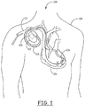
- an implantable medical device (IMD) system 100 which includes an implantable medical device 102, is shown in accordance with one exemplary embodiment of the present teachings.
- the implantable medical device 102 takes the form of a defibrillator and may be implanted within a patient 104 for providing a therapeutic electric shock to the patient's heart 106. It will be appreciated however, that the implantable medical device 102 may alternatively take the form of various other medical devices including, but not necessarily limited to, a pacemaker, a cardioverter, neural stimulator, drug administering device, etc. without departing from the scope of the present teachings.
- the implantable medical device 102 can be housed within a hermetically sealed, biologically inert outer container or housing, which may itself be conductive and also serve as an electrode, if appropriate for the IMD application.
- One or more leads are electrically coupled to the implantable device 102.
- the leads 108 can extend into the patient's heart 106 via a vein 112.
- the leads 108 can have one or more exposed conductive electrodes 116 for sensing cardiac activity and/or providing a stimulating voltage to the heart 106.
- the implantable medical device 102 comprises a capacitor bank 120, which includes one or more capacitors (not shown) disposed therein that store energy provided by a battery (not shown) within the implantable medical device 102.
- the capacitor bank 120 stores the energy from the battery to deliver a therapeutic electric shock via the leads 108 to defibrillate the patient's heart 106. That is, when the implantable medical device 102 determines that the cardiac therapy/stimulating electric shock is needed to produce a normal sinus rhythm of the heart 106, the capacitors in the capacitor bank 120 are charged to a pre-determined charge level by the battery. When the implantable medical device 102 determines that a therapeutic electric shock is needed, the charge stored in the capacitors is released by discharging the capacitors of the capacitor bank 120 through the patient's heart tissue via the leads 108.
- the present teachings provide methods of forming an electrode 10.
- the electrodes 10 are disclosed in connection with a capacitor assembly 20, one or more of which can be constructed for use similar to or in place of the capacitor bank 120 as mentioned above.
- the capacitor assembly 20 can be assembled from an anode 24, a cathode 26, and a separator 25 between the anode 24 and the cathode 26 and fitted into the capacitor case 30 with appropriate electrical connectors 32, 34 to the anode 24 and cathode 26.
- a capacitor 20 can be assembled from the anode 24, a cathode 26, and a separator 25 between the anode 24 and the cathode 26, and a plurality of the layers 24, 26 are stacked into a capacitor sub-assembly, electrically interconnected and fitted into a capacitor case 30 with appropriate electrical connectors 32, 34 to the anode 24 and cathode 26.
- the electrodes 10 of the present teachings are able to carry a high voltage of from about 150 to about 375 volts.
- the anode 24 can be electrically coupled to an anode lead wire 32 or pin.
- the anode lead wire 32 passes through the inner and outer surfaces of the capacitor case 30 via a feed-through 36.
- the cathode 26 can be similarly coupled to a cathode lead 34 which passes through the inner and outer surfaces of the capacitor case 30 via a feed-through 38.
- the capacitor case 30 may be used as an electrical connection in the cathode 26.
- the capacitor case 30 can be filled with a fluid electrolyte 40 which provides a current path between the anode 24 and the cathode 26. It is understood that although the present teachings provide a more detailed description of the anode 24, that the present teachings can be applied to formation of the cathode 26 as well.
- the anode 24 of the present teachings further comprises an anode body 16.
- the various parts of the anode 24 can be made of any suitable metal including, but not limited to, aluminum, tantalum, niobium, titanium, zirconium, etc., all of which form adherent, electrically insulating metal-oxide films upon anodic polarization in electrically conductive solutions. Combinations of the above-identified materials and others are also within the scope of the present teachings.
- the lead wire 32 can be pre-treated to improve subsequent bonding to the anode body 16.
- a small volume of metal powder 50 is applied to the lead wire 32 and subsequently vacuum sintered onto a portion of the lead wire 32.
- this sintering can be conducted at a temperature of above 1100 degrees C, more particularly from about 1350 degrees C to about 1600 degrees C.
- the sintering can be conducted at a temperature of about 1550 degrees C.
- the temperature can be modified depending on the materials, but is conducted at a sufficiently low temperature to substantially retain the metal powder morphology.
- the particulate metal 50 can be applied to the lead wire 32 in the form of a metal powder or as a slurry.
- the particulate metal 50 can be applied to a region of the lead wire 32 to form a contact region 28. As illustrated, the contact region 28 can be formed of a discrete length of the lead wire 32 as this portion will be embedded in the anode 24.
- the coated, unsintered lead wire 32 (or green wire) can be placed in a die to compress the particulate metal 50 around the lead wire 32 to form a powder compact.
- the powder compact exhibits sufficient strength to enable easy handling and placement in the vacuum sintering furnace. It is understood that the die to form the contact region 28 can be much smaller than a die used to form the anode body 16.
- the lead wire 32 and particulate metal 50 within the die can then be subjected to a vacuum sintering process, where heat is applied in a high vacuum environment, to adhere the particulate metal 50 at the contact region 28. This forms a "prepared" lead wire or pin 32.
- the prepared lead wire 32 with the contact region 28 provides a better interface and substrate to which to adhere the anode body 16. This increases the success of the subsequent processing steps necessary to produce a functional capacitor and increases overall production process yields for anodes processed using de-oxidation sintering.
- pre-treatment of the lead wire 32 to improve subsequent bonding to anode body 16 during de-oxidation sintering is accomplished by de-oxidizing lead wire 32 by itself prior to embedding it into the anode body 16.
- the lead wire 32 can be placed in a chamber 60 for de-oxidation.
- De-oxidation sintering differs from the traditional type sintering referenced above as de-oxidation sintering can be conducted at a lower temperature, in a selected gaseous environment, and the metal bonding can be slightly different as will be detailed later herein. Applicants have found that the de-oxidation sintering process facilitates forming smaller capacitors for space-critical applications which are capable of handling high voltage and is therefore beneficial.
- a problem in using de-oxidation sintering has been the establishment of a proper bond between anode and the lead wire The complicated methods used to overcome this problem with other lead wire to anode body bonding techniques are a primary disincentive to the use of de-oxidation sintering for electrode production.
- the present teachings provide straightforward solutions to the lead wire-anode body bonding problem and thereby significantly enhance manufacturability of electrodes processed by de-oxidation sintering.
- the present teachings further improve the bonding by implementing a liquid reactive metal in addition to the vapor of the reactive metal during pre-treatment of the lead wire by de-oxidation.
- De-oxidation and de-oxidation sintering comprise applying heat and pressure in a metal vapor (M+) atmosphere.
- M+ metal vapor
- the de-oxidation sintering of tantalum capacitor anodes can be conducted at a temperature of about 1150 degrees C. This temperature is significantly lower than the 1350 to 1600 degrees C temperature used in the traditional vacuum sintering process detailed above.
- the lead wire de-oxidation and the de-oxidation sintering can be conducted in a vessel 60, which in various embodiments can be a substantially hermetic vessel, in the presence of a metal vapor, indicated by the symbol M + .
- the metal vapor is provided from a liquefied reactive metal (indicated as M-M) retained in the bottom of the vessel 60. As the temperature increases, at least some of the metal vaporizes.
- M-M liquefied reactive metal
- the liquid reactive metal at the bottom of the vessel 60 contacts a region of the lead wire 32.
- the selected region of the lead wire is submerged or immersed in the liquid reactive metal.
- the remaining portions of the lead wire 16 are subjected to the metal vapor within the vessel 60. It is understood that increasing the size of the liquid reactive metal in the bottom of the vessel or using a larger vessel will assure appropriate liquid immersion for the process. This also facilitates batch processing or a series of processes.
- the metal which forms the metal vapor atmosphere generally has a higher affinity for oxygen than the lead wire 32 and the particulate metal 50 used for the anode 24.
- the metal vapor could comprise a metal having a higher affinity for oxygen.
- the metal vapor atmosphere is selected from the group consisting of magnesium and calcium.
- the de-oxidation sintering facilitates production of an anode 24 with a more uniform particle size distribution than is obtainable by conventional vacuum sintering of commercially available powders. Under appropriate conditions the more uniform particle size obtainable by de-oxidation sintering can result in a capacitor anode 24 exhibiting significantly greater capacitance per unit volume than is obtained by conventional vacuum sintering.
- an oxide layer or particles may form on all or part of the electrode surface or the pin surface, and oxide formation is not limited to the contact or selected region as detailed above.
- magnesium oxide particles or a magnesium oxide layer can form where a magnesium vapor can be used in the de-oxidation sintering process.
- the acid treatment such as a bath, dip, or spray removes the oxides without damaging the underlying substrate.
- Suitable acids for the treatment include weak solutions of an inorganic acid, such as hydrochloric acid, as a non-limiting example.
- the washing can be followed with a rinse using de-ionized water, for example, and a subsequent drying.
- the pre-treated pin 32 can then be pressed into the powder for the anode body 16 and ultimately the anode 24.
- the anode body 16 can be formed by building up additional or second powdered metal onto the prepared lead pin 32.
- the second or subsequent metal powder or slurry can be applied over the contact region 28 and subjected to a de-oxidation sintering process as shown in Figure 5B .
- the de-oxidation sintering secures the second metal which forms the anode body 16 over the prepared lead wire 32.
- the same metal or at least one different metal can be used to form the anode body 16 and the contact region 28.
- the surface of the anode 24 can be cleaned to remove the reactive metal oxides formed during processing.
- the surface of the anode 24 can be cleaned to remove the reactive metal oxides formed during processing.
- Production of a high quality capacitor anode may comprise a first anodic oxide formation step, a thermal treatment or annealing process, and a second anodic oxide formation step, as is well known in the electrolytic capacitor art.
- an anode 24 can be incorporated into a capacitor 20 which can be connected to the implantable medical device system 100.
- a therapy can then be administered from the implantable medical device system 100 to the patient.
- the therapy can include exposing the capacitor to a voltage of from between 150 to 375 volts, and all sub-ranges in between.
- An exemplary therapy is treatment of an arrhythmia.
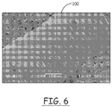
- FIG. 6 One of ten as-received centerless-ground lead wires 200 is represented in Figure 6 .
- the lead wires were pressed into a tantalum powder body to form test anodes and were processed through de-oxidation sintering and acid leaching. An attempt was then made to form an anodic oxide up to a formation potential of 260V.
- Two of the test anodes including untreated lead wires 200 failed second formation or forming an anodic oxide capable of withstanding the desired 260V formation potential.
- Eight of the test anodes were successfully formed to a potential of 260V.
- one of the test anodes which included untreated lead wires 200 exhibited more than a five-fold increase in the equivalent series resistance (ESR) as compared to the lot average. This indicated poor electrical connection between the anode body and lead wire.
- ESR equivalent series resistance
- Yield through working electrolyte charging (WEC) for the first ten of the twenty anodes comprising PDO pins was 100%. Three additional de-oxidation sintering runs employing anodes comprising PDO pins were done over the course of roughly 4 weeks. Overall yield through WEC for all four runs using PDO pins was greater than 97%. This result improved the overall yield relative to any previous groups of experimental anodes processed by de-oxidation sintering.
- Figure 7 shows the surface of a standard pin following a de-oxidation process but before leaching.
- a very high density of magnesium oxide (MgO) crystallites 302 can be seen on the surface of the lead wire 300.
- Figure 8 depicts a region of Figure 7 at a higher magnification, where the morphology of the MgO crystallites 302 is evident. It is believed to be likely that these crystallites 302 were formed by coagulation of a quasi-continuous film of MgO that formed on the surface at a relatively early stage of the de-oxidation process as the (presumably relatively uniformly distributed) oxygen in the lead wire 300 reacted with magnesium liquid or vapor arriving at the lead wire 300 surface.
- MgO magnesium oxide
- the leaching process removes substantially all of the MgO crystallites.
- the oxygen content of as-received and PDO lead wires were compared using secondary ion mass spectrometry (SIMS).
- SIMS secondary ion mass spectrometry
- Dynamic SIMS analysis employing cesium primary ions reveals that the sub-surface oxygen content of a PDO lead wire is about twenty or more times lower than the sub-surface oxygen content of an as-received lead wire.
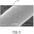
- Figure 10 depicts the surface of a PDO lead wire 300 that was pressed into a test anode and subsequently processed through de-oxidation sintering, acid leaching, and formation.
- the anode body 304 was mechanically broken away to reveal the lead wire 300 surface. It is clear that residue and clusters of sintered and formed powder remain bonded to the pin surface.
- the comparative example shown in Figure 6 shows the surface of an as-received pin that was pressed into a test anode and subsequently processed through de-oxidation sintering and formation under the same conditions as the PDO pin 300 of Figure 10 .
- the lead wire 200 of Figure 6 shows very little bonding of the powder to the lead wire 200.
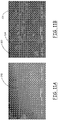
- Figure 11A depicts a PDO pin 300 that was de-oxidized by exposure to substantially only magnesium vapor during the de-oxidation process. After leaching to remove the magnesium oxide reaction products, the pin 300 was embedded in an anode body 304 and the pin-anode body composite were de-oxidation sintered, again by exposure to substantially only magnesium vapor. A large fraction of the anode body 304 was then mechanically broken away, revealing relatively little bonding of the anode body 304 powder to the pin 300 surface.
- Figure 11B depicts the PDO lead wire 300 that was de-oxidized by immersion in liquid magnesium.
- the liquid magnesium was in direct contact with the selected region of the pin 300.
- the pin 300 was embedded in an anode body 304, and the pin-anode body composite was de-oxidation sintered by exposure to substantially only magnesium vapor.
- the majority of the anode body 304 was mechanically broken away to reveal the lead wire 300 surface underneath. Clusters of the anode body 304 remained bonded at various points along the lead wire 300.
- the clusters of the anode body 304 in Figure 11B show that pre-treatment with liquid magnesium improves bonding of the anode body 304 to the lead wire 300.
Landscapes
- Engineering & Computer Science (AREA)
- Power Engineering (AREA)
- Microelectronics & Electronic Packaging (AREA)
- Health & Medical Sciences (AREA)
- Nuclear Medicine, Radiotherapy & Molecular Imaging (AREA)
- Cardiology (AREA)
- Heart & Thoracic Surgery (AREA)
- Biomedical Technology (AREA)
- Manufacturing & Machinery (AREA)
- Radiology & Medical Imaging (AREA)
- Life Sciences & Earth Sciences (AREA)
- Animal Behavior & Ethology (AREA)
- General Health & Medical Sciences (AREA)
- Public Health (AREA)
- Veterinary Medicine (AREA)
- Fixed Capacitors And Capacitor Manufacturing Machines (AREA)
- Powder Metallurgy (AREA)
Claims (14)
- Procédé de préparation d'une électrode pour un dispositif médical, comportant les étapes consistant à :a. prétraiter une région (28) d'un fil de sortie électriquement conducteur (32) en mettant en contact la région avec un liquide d'un métal réactif ;b. retirer des oxydes métalliques réactifs formés sur le fil de sortie dus au contact avec le liquide du métal réactif ;c. incorporer le fil de sortie dans un compact de poudre métallique (50) ;d. soumettre le compact de poudre métallique et le fil de sortie à un frittage de désoxydation en présence d'une vapeur du métal réactif ; ete. retirer les oxydes métalliques réactifs formés pendant le processus de frittage de désoxydation.
- Procédé selon la revendication 1, dans lequel la mise en contact de la région du fil de sortie avec le liquide du métal réactif comporte l'immersion de la région du fil de sortie dans le liquide du métal réactif.
- Procédé selon la revendication 1, dans lequel le pré-traitement du fil de sortie comporte en outre le retrait des oxydes métalliques réactifs formés avant l'incorporation du fil de sortie dans le compact de poudre métallique.
- Procédé selon la revendication 1, dans lequel le métal réactif a une affinité vis-à-vis de l'oxygène plus élevée que la poudre métallique.
- Procédé selon la revendication 1, dans lequel le métal réactif est choisi parmi le groupe constitué du magnésium et du calcium.
- Procédé selon la revendication 1, comportant en outre la conduction du frittage de désoxydation à une température supérieure à 1 100 degrés C.
- Procédé selon la revendication 1, dans lequel le retrait des oxydes de l'électrode comporte la lixiviation des oxydes dans un bain acide.
- Procédé selon la revendication 1, dans lequel la poudre métallique comporte une poudre de tantale.
- Procédé selon la revendication 1, dans lequel l'électrode comporte une anode de condensateur.
- Procédé de préparation d'une anode de condensateur en métal valve comportant les étapes consistant à :prétraiter au moins une portion d'un fil de sortie en métal valve avec un liquide d'un métal réactif ;incorporer le fil de sortie en métal valve (32) à l'intérieur d'un compact de poudre métallique (50), et exécuter un processus de frittage de désoxydation en présence d'une vapeur du métal réactif au cours duquel le fil de sortie en métal valve et le compact de poudre métallique sont assemblés.
- Procédé selon la revendication 10, dans lequel le pré-traitement du fil de sortie comporte une désoxydation du fil de sortie, dans laquelle au moins la portion du fil de sortie est en contact direct avec le liquide du métal réactif, et un retrait des oxydes métalliques réactifs formés avant l'incorporation du fil de sortie dans le compact de poudre métallique.
- Procédé selon la revendication 10, dans lequel le métal réactif a une affinité vis-à-vis de l'oxygène plus élevée que la poudre métallique.
- Procédé selon la revendication 10, dans lequel le métal réactif est choisi parmi le groupe constitué du magnésium et du calcium.
- Procédé selon la revendication 10, dans lequel la poudre métallique comporte une poudre de tantale.
Applications Claiming Priority (3)
| Application Number | Priority Date | Filing Date | Title |
|---|---|---|---|
| US12/429,749 US8298478B2 (en) | 2009-04-24 | 2009-04-24 | Method of preparing an electrode |
| US12/607,331 US20100274307A1 (en) | 2009-04-24 | 2009-10-28 | Methods of preparing an electrode |
| PCT/US2010/030961 WO2010123722A1 (fr) | 2009-04-24 | 2010-04-14 | Procédés de préparation d'une électrode |
Publications (2)
| Publication Number | Publication Date |
|---|---|
| EP2454745A1 EP2454745A1 (fr) | 2012-05-23 |
| EP2454745B1 true EP2454745B1 (fr) | 2016-06-08 |
Family
ID=42319047
Family Applications (1)
| Application Number | Title | Priority Date | Filing Date |
|---|---|---|---|
| EP10715627.5A Active EP2454745B1 (fr) | 2009-04-24 | 2010-04-14 | Methode de preparation d'une electrode |
Country Status (3)
| Country | Link |
|---|---|
| US (2) | US8298478B2 (fr) |
| EP (1) | EP2454745B1 (fr) |
| WO (1) | WO2010123722A1 (fr) |
Families Citing this family (7)
| Publication number | Priority date | Publication date | Assignee | Title |
|---|---|---|---|---|
| CA2661469A1 (fr) * | 2008-04-11 | 2009-10-11 | Andre Foucault | Appareil de reeducation des jambes |
| US8477479B2 (en) * | 2011-01-12 | 2013-07-02 | Avx Corporation | Leadwire configuration for a planar anode of a wet electrolytic capacitor |
| GB2512481B (en) | 2013-03-15 | 2018-05-30 | Avx Corp | Wet electrolytic capacitor for use at high temperatures |
| GB2512486B (en) | 2013-03-15 | 2018-07-18 | Avx Corp | Wet electrolytic capacitor |
| US10290430B2 (en) * | 2014-11-24 | 2019-05-14 | Avx Corporation | Wet Electrolytic Capacitor for an Implantable Medical Device |
| US9786440B2 (en) * | 2014-12-17 | 2017-10-10 | Avx Corporation | Anode for use in a high voltage electrolytic capacitor |
| US20190287730A1 (en) * | 2018-03-15 | 2019-09-19 | Kemet Electronics Corporation | Method to Reduce Anode Lead Wire Embrittlement in Capacitors |
Family Cites Families (20)
| Publication number | Priority date | Publication date | Assignee | Title |
|---|---|---|---|---|
| DE3130392C2 (de) * | 1981-07-31 | 1985-10-17 | Hermann C. Starck Berlin, 1000 Berlin | Verfahren zur Herstellung reiner agglomerierter Ventilmetallpulver für Elektrolytkondensatoren, deren Verwendung und Verfahren zur Herstellung von Sinteranoden |
| DE3309891A1 (de) * | 1983-03-18 | 1984-10-31 | Hermann C. Starck Berlin, 1000 Berlin | Verfahren zur herstellung von ventilmetallanoden fuer elektrolytkondensatoren |
| US4574333A (en) * | 1985-06-12 | 1986-03-04 | Union Carbide Corporation | Low density tantalum anode bodies |
| US4945452A (en) * | 1989-11-30 | 1990-07-31 | Avx Corporation | Tantalum capacitor and method of making same |
| JP3324658B2 (ja) * | 1992-07-21 | 2002-09-17 | 東芝タンガロイ株式会社 | 微細孔を有する焼結合金及びその製造方法 |
| JP3801660B2 (ja) * | 1994-05-30 | 2006-07-26 | ローム株式会社 | タンタル固体電解コンデンサ用コンデンサ素子の製造方法 |
| DE19525143A1 (de) * | 1995-07-11 | 1997-01-16 | Biotronik Mess & Therapieg | Elektrolytkondensator, insbesondere Tantal-Elektrolytkondensator |
| US6051326A (en) | 1997-04-26 | 2000-04-18 | Cabot Corporation | Valve metal compositions and method |
| DE60033076T2 (de) * | 1999-04-16 | 2007-08-30 | Matsushita Electric Industrial Co., Ltd., Kadoma | Anodische Elektrode für Elektrolytkondensator und Verfahren zu ihrer Herstellung |
| US6558447B1 (en) * | 1999-05-05 | 2003-05-06 | H.C. Starck, Inc. | Metal powders produced by the reduction of the oxides with gaseous magnesium |
| US6447570B1 (en) * | 2000-11-30 | 2002-09-10 | Vishay Sprague, Inc. | Sintered Tantalum and Niobium capacitor pellets doped with Nitrogen, and method of making the same |
| US6885548B2 (en) * | 2002-04-17 | 2005-04-26 | Medtronic, Inc. | Methods of fabricating anode layers of flat electrolytic capacitors |
| TWI225656B (en) * | 2002-07-26 | 2004-12-21 | Sanyo Electric Co | Electrolytic capacitor and a fabrication method therefor |
| US7002790B2 (en) * | 2002-09-30 | 2006-02-21 | Medtronic, Inc. | Capacitor in an implantable medical device |
| US6819544B1 (en) * | 2003-05-30 | 2004-11-16 | Medtronic, Inc. | Dual-anode electrolytic capacitor for use in an implantable medical device |
| US7224576B2 (en) * | 2003-10-23 | 2007-05-29 | Medtronic, Inc. | High capacitance electrode and methods of producing same |
| US7952853B2 (en) * | 2004-04-27 | 2011-05-31 | Medtronic, Inc. | Capacitor electrolyte |
| EP1761352B1 (fr) * | 2004-06-24 | 2008-08-13 | H.C. Starck Inc. | Production de poudres de metaux valves presentant de meilleures proprietes physiques et electriques |
| US7731893B2 (en) * | 2006-12-18 | 2010-06-08 | Kemet Electronics Corporation | Method for making anodes for electrolytic capacitor with high volumetric efficiency |
| US20090279233A1 (en) * | 2008-05-12 | 2009-11-12 | Yuri Freeman | High volumetric efficiency anodes for electrolytic capacitors |
-
2009
- 2009-04-24 US US12/429,749 patent/US8298478B2/en active Active
- 2009-10-28 US US12/607,331 patent/US20100274307A1/en not_active Abandoned
-
2010
- 2010-04-14 WO PCT/US2010/030961 patent/WO2010123722A1/fr not_active Ceased
- 2010-04-14 EP EP10715627.5A patent/EP2454745B1/fr active Active
Also Published As
| Publication number | Publication date |
|---|---|
| US8298478B2 (en) | 2012-10-30 |
| US20100274307A1 (en) | 2010-10-28 |
| WO2010123722A1 (fr) | 2010-10-28 |
| EP2454745A1 (fr) | 2012-05-23 |
| US20100274337A1 (en) | 2010-10-28 |
Similar Documents
| Publication | Publication Date | Title |
|---|---|---|
| US8298478B2 (en) | Method of preparing an electrode | |
| CN102449714B (zh) | 密闭湿式电解电容器 | |
| US6801424B1 (en) | Electrolytic capacitor for use in an implantable medical device | |
| US7342774B2 (en) | Advanced valve metal anodes with complex interior and surface features and methods for processing same | |
| US7256982B2 (en) | Electrolytic capacitor | |
| US6807048B1 (en) | Electrolytic capacitor for use in an implantable medical device | |
| US8086312B2 (en) | Capacitors for medical devices | |
| EP2442866B1 (fr) | Electrodes à densité d'énergie volumétrique | |
| US20040240153A1 (en) | Dual-anode electrolytic capacitor for use in an implantable medical device | |
| CA2500463A1 (fr) | Condensateur et appareil medical implantable comportant un tel condensateur | |
| US9514886B1 (en) | Cryogenic grinding of tantalum for use in capacitor manufacture | |
| US9721730B1 (en) | Capacitor having multiple anodes housed in a stacked casing | |
| US20100055570A1 (en) | Biobattery with nanocrystalline material anode | |
| US7286336B2 (en) | Plasma treatment of anodic oxides for electrolytic capacitors | |
| US7006347B1 (en) | Low deformation electrolytic capacitor | |
| US7459369B2 (en) | High capacitance low resistance electrode | |
| US20230420191A1 (en) | Electrical component and method of forming same | |
| CN114068187A (zh) | 电气部件及其形成方法 | |
| HK1170597B (en) | Hermetically sealed wet electrolytic capacitor |
Legal Events
| Date | Code | Title | Description |
|---|---|---|---|
| PUAI | Public reference made under article 153(3) epc to a published international application that has entered the european phase |
Free format text: ORIGINAL CODE: 0009012 |
|
| 17P | Request for examination filed |
Effective date: 20120312 |
|
| AK | Designated contracting states |
Kind code of ref document: A1 Designated state(s): AT BE BG CH CY CZ DE DK EE ES FI FR GB GR HR HU IE IS IT LI LT LU LV MC MK MT NL NO PL PT RO SE SI SK SM TR |
|
| DAX | Request for extension of the european patent (deleted) | ||
| REG | Reference to a national code |
Ref country code: DE Ref legal event code: R079 Ref document number: 602010033914 Country of ref document: DE Free format text: PREVIOUS MAIN CLASS: H01G0009008000 Ipc: A61N0001050000 |
|
| GRAP | Despatch of communication of intention to grant a patent |
Free format text: ORIGINAL CODE: EPIDOSNIGR1 |
|
| RIC1 | Information provided on ipc code assigned before grant |
Ipc: A61N 1/05 20060101AFI20151109BHEP Ipc: H01G 9/052 20060101ALI20151109BHEP Ipc: H01G 9/00 20060101ALI20151109BHEP Ipc: H01G 9/012 20060101ALI20151109BHEP Ipc: H01G 9/008 20060101ALI20151109BHEP |
|
| INTG | Intention to grant announced |
Effective date: 20151215 |
|
| GRAS | Grant fee paid |
Free format text: ORIGINAL CODE: EPIDOSNIGR3 |
|
| GRAA | (expected) grant |
Free format text: ORIGINAL CODE: 0009210 |
|
| AK | Designated contracting states |
Kind code of ref document: B1 Designated state(s): AT BE BG CH CY CZ DE DK EE ES FI FR GB GR HR HU IE IS IT LI LT LU LV MC MK MT NL NO PL PT RO SE SI SK SM TR |
|
| REG | Reference to a national code |
Ref country code: GB Ref legal event code: FG4D |
|
| REG | Reference to a national code |
Ref country code: CH Ref legal event code: EP |
|
| REG | Reference to a national code |
Ref country code: IE Ref legal event code: FG4D |
|
| REG | Reference to a national code |
Ref country code: AT Ref legal event code: REF Ref document number: 804776 Country of ref document: AT Kind code of ref document: T Effective date: 20160715 |
|
| REG | Reference to a national code |
Ref country code: DE Ref legal event code: R096 Ref document number: 602010033914 Country of ref document: DE |
|
| REG | Reference to a national code |
Ref country code: LT Ref legal event code: MG4D |
|
| REG | Reference to a national code |
Ref country code: NL Ref legal event code: MP Effective date: 20160608 |
|
| PG25 | Lapsed in a contracting state [announced via postgrant information from national office to epo] |
Ref country code: FI Free format text: LAPSE BECAUSE OF FAILURE TO SUBMIT A TRANSLATION OF THE DESCRIPTION OR TO PAY THE FEE WITHIN THE PRESCRIBED TIME-LIMIT Effective date: 20160608 Ref country code: LT Free format text: LAPSE BECAUSE OF FAILURE TO SUBMIT A TRANSLATION OF THE DESCRIPTION OR TO PAY THE FEE WITHIN THE PRESCRIBED TIME-LIMIT Effective date: 20160608 Ref country code: NO Free format text: LAPSE BECAUSE OF FAILURE TO SUBMIT A TRANSLATION OF THE DESCRIPTION OR TO PAY THE FEE WITHIN THE PRESCRIBED TIME-LIMIT Effective date: 20160908 |
|
| REG | Reference to a national code |
Ref country code: AT Ref legal event code: MK05 Ref document number: 804776 Country of ref document: AT Kind code of ref document: T Effective date: 20160608 |
|
| PG25 | Lapsed in a contracting state [announced via postgrant information from national office to epo] |
Ref country code: GR Free format text: LAPSE BECAUSE OF FAILURE TO SUBMIT A TRANSLATION OF THE DESCRIPTION OR TO PAY THE FEE WITHIN THE PRESCRIBED TIME-LIMIT Effective date: 20160909 Ref country code: SE Free format text: LAPSE BECAUSE OF FAILURE TO SUBMIT A TRANSLATION OF THE DESCRIPTION OR TO PAY THE FEE WITHIN THE PRESCRIBED TIME-LIMIT Effective date: 20160608 Ref country code: ES Free format text: LAPSE BECAUSE OF FAILURE TO SUBMIT A TRANSLATION OF THE DESCRIPTION OR TO PAY THE FEE WITHIN THE PRESCRIBED TIME-LIMIT Effective date: 20160608 Ref country code: LV Free format text: LAPSE BECAUSE OF FAILURE TO SUBMIT A TRANSLATION OF THE DESCRIPTION OR TO PAY THE FEE WITHIN THE PRESCRIBED TIME-LIMIT Effective date: 20160608 Ref country code: NL Free format text: LAPSE BECAUSE OF FAILURE TO SUBMIT A TRANSLATION OF THE DESCRIPTION OR TO PAY THE FEE WITHIN THE PRESCRIBED TIME-LIMIT Effective date: 20160608 |
|
| PG25 | Lapsed in a contracting state [announced via postgrant information from national office to epo] |
Ref country code: SK Free format text: LAPSE BECAUSE OF FAILURE TO SUBMIT A TRANSLATION OF THE DESCRIPTION OR TO PAY THE FEE WITHIN THE PRESCRIBED TIME-LIMIT Effective date: 20160608 Ref country code: IS Free format text: LAPSE BECAUSE OF FAILURE TO SUBMIT A TRANSLATION OF THE DESCRIPTION OR TO PAY THE FEE WITHIN THE PRESCRIBED TIME-LIMIT Effective date: 20161008 Ref country code: RO Free format text: LAPSE BECAUSE OF FAILURE TO SUBMIT A TRANSLATION OF THE DESCRIPTION OR TO PAY THE FEE WITHIN THE PRESCRIBED TIME-LIMIT Effective date: 20160608 Ref country code: EE Free format text: LAPSE BECAUSE OF FAILURE TO SUBMIT A TRANSLATION OF THE DESCRIPTION OR TO PAY THE FEE WITHIN THE PRESCRIBED TIME-LIMIT Effective date: 20160608 Ref country code: IT Free format text: LAPSE BECAUSE OF FAILURE TO SUBMIT A TRANSLATION OF THE DESCRIPTION OR TO PAY THE FEE WITHIN THE PRESCRIBED TIME-LIMIT Effective date: 20160608 Ref country code: CZ Free format text: LAPSE BECAUSE OF FAILURE TO SUBMIT A TRANSLATION OF THE DESCRIPTION OR TO PAY THE FEE WITHIN THE PRESCRIBED TIME-LIMIT Effective date: 20160608 |
|
| PG25 | Lapsed in a contracting state [announced via postgrant information from national office to epo] |
Ref country code: PT Free format text: LAPSE BECAUSE OF FAILURE TO SUBMIT A TRANSLATION OF THE DESCRIPTION OR TO PAY THE FEE WITHIN THE PRESCRIBED TIME-LIMIT Effective date: 20161010 Ref country code: BE Free format text: LAPSE BECAUSE OF FAILURE TO SUBMIT A TRANSLATION OF THE DESCRIPTION OR TO PAY THE FEE WITHIN THE PRESCRIBED TIME-LIMIT Effective date: 20160608 Ref country code: SM Free format text: LAPSE BECAUSE OF FAILURE TO SUBMIT A TRANSLATION OF THE DESCRIPTION OR TO PAY THE FEE WITHIN THE PRESCRIBED TIME-LIMIT Effective date: 20160608 Ref country code: PL Free format text: LAPSE BECAUSE OF FAILURE TO SUBMIT A TRANSLATION OF THE DESCRIPTION OR TO PAY THE FEE WITHIN THE PRESCRIBED TIME-LIMIT Effective date: 20160608 Ref country code: AT Free format text: LAPSE BECAUSE OF FAILURE TO SUBMIT A TRANSLATION OF THE DESCRIPTION OR TO PAY THE FEE WITHIN THE PRESCRIBED TIME-LIMIT Effective date: 20160608 |
|
| REG | Reference to a national code |
Ref country code: DE Ref legal event code: R097 Ref document number: 602010033914 Country of ref document: DE |
|
| PLBE | No opposition filed within time limit |
Free format text: ORIGINAL CODE: 0009261 |
|
| STAA | Information on the status of an ep patent application or granted ep patent |
Free format text: STATUS: NO OPPOSITION FILED WITHIN TIME LIMIT |
|
| REG | Reference to a national code |
Ref country code: FR Ref legal event code: PLFP Year of fee payment: 8 |
|
| 26N | No opposition filed |
Effective date: 20170309 |
|
| PG25 | Lapsed in a contracting state [announced via postgrant information from national office to epo] |
Ref country code: SI Free format text: LAPSE BECAUSE OF FAILURE TO SUBMIT A TRANSLATION OF THE DESCRIPTION OR TO PAY THE FEE WITHIN THE PRESCRIBED TIME-LIMIT Effective date: 20160608 Ref country code: DK Free format text: LAPSE BECAUSE OF FAILURE TO SUBMIT A TRANSLATION OF THE DESCRIPTION OR TO PAY THE FEE WITHIN THE PRESCRIBED TIME-LIMIT Effective date: 20160608 |
|
| REG | Reference to a national code |
Ref country code: CH Ref legal event code: PL |
|
| GBPC | Gb: european patent ceased through non-payment of renewal fee |
Effective date: 20170414 |
|
| REG | Reference to a national code |
Ref country code: IE Ref legal event code: MM4A |
|
| PG25 | Lapsed in a contracting state [announced via postgrant information from national office to epo] |
Ref country code: MC Free format text: LAPSE BECAUSE OF FAILURE TO SUBMIT A TRANSLATION OF THE DESCRIPTION OR TO PAY THE FEE WITHIN THE PRESCRIBED TIME-LIMIT Effective date: 20160608 |
|
| PG25 | Lapsed in a contracting state [announced via postgrant information from national office to epo] |
Ref country code: CH Free format text: LAPSE BECAUSE OF NON-PAYMENT OF DUE FEES Effective date: 20170430 Ref country code: GB Free format text: LAPSE BECAUSE OF NON-PAYMENT OF DUE FEES Effective date: 20170414 Ref country code: LI Free format text: LAPSE BECAUSE OF NON-PAYMENT OF DUE FEES Effective date: 20170430 Ref country code: LU Free format text: LAPSE BECAUSE OF NON-PAYMENT OF DUE FEES Effective date: 20170414 |
|
| REG | Reference to a national code |
Ref country code: FR Ref legal event code: PLFP Year of fee payment: 9 |
|
| PG25 | Lapsed in a contracting state [announced via postgrant information from national office to epo] |
Ref country code: IE Free format text: LAPSE BECAUSE OF NON-PAYMENT OF DUE FEES Effective date: 20170414 |
|
| PG25 | Lapsed in a contracting state [announced via postgrant information from national office to epo] |
Ref country code: MT Free format text: LAPSE BECAUSE OF NON-PAYMENT OF DUE FEES Effective date: 20170414 |
|
| PG25 | Lapsed in a contracting state [announced via postgrant information from national office to epo] |
Ref country code: HU Free format text: LAPSE BECAUSE OF FAILURE TO SUBMIT A TRANSLATION OF THE DESCRIPTION OR TO PAY THE FEE WITHIN THE PRESCRIBED TIME-LIMIT; INVALID AB INITIO Effective date: 20100414 |
|
| PG25 | Lapsed in a contracting state [announced via postgrant information from national office to epo] |
Ref country code: BG Free format text: LAPSE BECAUSE OF FAILURE TO SUBMIT A TRANSLATION OF THE DESCRIPTION OR TO PAY THE FEE WITHIN THE PRESCRIBED TIME-LIMIT Effective date: 20160608 |
|
| PG25 | Lapsed in a contracting state [announced via postgrant information from national office to epo] |
Ref country code: CY Free format text: LAPSE BECAUSE OF NON-PAYMENT OF DUE FEES Effective date: 20160608 |
|
| PG25 | Lapsed in a contracting state [announced via postgrant information from national office to epo] |
Ref country code: MK Free format text: LAPSE BECAUSE OF FAILURE TO SUBMIT A TRANSLATION OF THE DESCRIPTION OR TO PAY THE FEE WITHIN THE PRESCRIBED TIME-LIMIT Effective date: 20160608 |
|
| PG25 | Lapsed in a contracting state [announced via postgrant information from national office to epo] |
Ref country code: TR Free format text: LAPSE BECAUSE OF FAILURE TO SUBMIT A TRANSLATION OF THE DESCRIPTION OR TO PAY THE FEE WITHIN THE PRESCRIBED TIME-LIMIT Effective date: 20160608 |
|
| PG25 | Lapsed in a contracting state [announced via postgrant information from national office to epo] |
Ref country code: HR Free format text: LAPSE BECAUSE OF FAILURE TO SUBMIT A TRANSLATION OF THE DESCRIPTION OR TO PAY THE FEE WITHIN THE PRESCRIBED TIME-LIMIT Effective date: 20160608 |
|
| PGFP | Annual fee paid to national office [announced via postgrant information from national office to epo] |
Ref country code: DE Payment date: 20250319 Year of fee payment: 16 |
|
| PGFP | Annual fee paid to national office [announced via postgrant information from national office to epo] |
Ref country code: FR Payment date: 20260319 Year of fee payment: 17 |