EP2454887B1 - Verfahren zur bereitstellung von einem asymmetrischen mehrfachruf zwischen mehreren netzknoten - Google Patents
Verfahren zur bereitstellung von einem asymmetrischen mehrfachruf zwischen mehreren netzknoten Download PDFInfo
- Publication number
- EP2454887B1 EP2454887B1 EP09777250.3A EP09777250A EP2454887B1 EP 2454887 B1 EP2454887 B1 EP 2454887B1 EP 09777250 A EP09777250 A EP 09777250A EP 2454887 B1 EP2454887 B1 EP 2454887B1
- Authority
- EP
- European Patent Office
- Prior art keywords
- call
- node
- asymmetric multipoint
- master node
- slave node
- Prior art date
- Legal status (The legal status is an assumption and is not a legal conclusion. Google has not performed a legal analysis and makes no representation as to the accuracy of the status listed.)
- Not-in-force
Links
- 238000000034 method Methods 0.000 title claims description 73
- 238000004891 communication Methods 0.000 claims description 64
- 230000004044 response Effects 0.000 claims description 12
- 238000004590 computer program Methods 0.000 claims description 9
- 230000011664 signaling Effects 0.000 description 17
- 238000010586 diagram Methods 0.000 description 8
- 230000008859 change Effects 0.000 description 4
- 230000008901 benefit Effects 0.000 description 3
- 238000013507 mapping Methods 0.000 description 3
- 230000001960 triggered effect Effects 0.000 description 3
- 230000006870 function Effects 0.000 description 2
- 230000000977 initiatory effect Effects 0.000 description 2
- 230000003287 optical effect Effects 0.000 description 2
- 230000001413 cellular effect Effects 0.000 description 1
- 238000010276 construction Methods 0.000 description 1
- 230000003111 delayed effect Effects 0.000 description 1
- 238000005516 engineering process Methods 0.000 description 1
- 239000003999 initiator Substances 0.000 description 1
- 230000007246 mechanism Effects 0.000 description 1
- 230000005012 migration Effects 0.000 description 1
- 238000013508 migration Methods 0.000 description 1
- 230000008569 process Effects 0.000 description 1
- 238000000926 separation method Methods 0.000 description 1
Images





Classifications
-
- H—ELECTRICITY
- H04—ELECTRIC COMMUNICATION TECHNIQUE
- H04M—TELEPHONIC COMMUNICATION
- H04M3/00—Automatic or semi-automatic exchanges
- H04M3/42—Systems providing special services or facilities to subscribers
- H04M3/56—Arrangements for connecting several subscribers to a common circuit, i.e. affording conference facilities
- H04M3/561—Arrangements for connecting several subscribers to a common circuit, i.e. affording conference facilities by multiplexing
-
- H—ELECTRICITY
- H04—ELECTRIC COMMUNICATION TECHNIQUE
- H04L—TRANSMISSION OF DIGITAL INFORMATION, e.g. TELEGRAPHIC COMMUNICATION
- H04L45/00—Routing or path finding of packets in data switching networks
- H04L45/50—Routing or path finding of packets in data switching networks using label swapping, e.g. multi-protocol label switch [MPLS]
Definitions
- the present invention generally relates to the technical field of asymmetric multipoint calls.
- the invention relates to a technique for providing an asymmetric multipoint call between a plurality of network nodes in a communication network.
- DCM Distributed Call and Connection Management
- a call is defined as an association between endpoints to support an instance of a network service.
- GMPLS can be used on a control plane for ASON/ASTN networks supporting DCM features. Accordingly, in communication networks supporting DCM features and using GMPLS protocols, a point-to-point call establishes a relationship between two endpoints based on which subsequent point-to-point connections may be generated.
- GMPLS Multiprotocol Label Switching
- PBB-TE Provider Backbone Bridging with Traffic Engineering
- GMPLS point-to-point call concept does not support multipoint services using point-to-multipoint connections.
- the GMPLS point-to-point call concept does not support assigning multiple calls to the same network connection.
- a method for providing an asymmetric multipoint call between a plurality of network nodes in a communication network according to claim 2 is provided.
- the asymmetric multipoint call is based on an association between at least three endpoints, i.e., the master node, the first slave node and the second slave node, for supporting a network service instance, e.g., a multipoint service.
- the asymmetry of the asymmetric multipoint call lies in the different data exchange provided between the master node and the first and second slave node.
- call management information is only exchanged between the master node and the first and the second slave node, however, not directly between the first and the second slave node bypassing the master node.
- the communication network supporting DCM features may be a network using the protocol specifications as defined in document ITU-T G.7713 "Distributed Call and Connection Management DCM" by the ITU .
- the communication network may be a data communication network in which functional entities regarding call management and connection management are implemented in a plurality of network nodes of the communication network, wherein connection and call management is performed based on an interoperation of the functional entities.
- the communication network may also be an ASTN and/or an ASON supporting DCM features, or an ASTN and/or an ASON supporting DCM features and using at least one GMPLS protocol.
- the master node, the first slave node and the second slave node may be any kind of active electronic devices that are attached to the communication network and are capable of sending, receiving and/or forwarding information via communication links.
- the call management information exclusively exchanged between the master node and the first and the second slave node may comprise identification information uniquely identifying the asymmetric multipoint call. Based on the identification information, an asymmetric multipoint call can be identified globally, i.e., domain wide, within the communication network.
- the identification information may comprise information regarding at least one of the network nodes participating in the asymmetric multipoint call, regarding the master node of the asymmetric multipoint call, and regarding a local identifier of the asymmetric multipoint call. Based on the local identifier, different asymmetric multipoint calls having the same endpoints (e.g., the master node and the first and the second slave node) can be distinguished.
- the identification information may alternatively or additionally comprise information regarding slave nodes participating in the asymmetric multipoint call, e.g., a slave node list.
- extended call information may be exchanged, e.g., for synchronization procedures.
- the method may comprise the further step of receiving, by at least the first slave node, notifications of changes of the identification information from the master node.
- the method may comprise the step of receiving, by at least the first slave node, information regarding slave nodes participating in the asymmetric multipoint call, e.g., a list of slave nodes, from the master node.
- These notifications may be provided periodically by the master node to the first slave node. For scalability reasons, the notifications may only comprise information regarding status changes.
- the first slave node may send an acknowledge message in response to a received notification to the master node.
- Call management information is communicated via the master node to the slave nodes. Accordingly, failure of the master node may disrupt the asymmetric multipoint call. Therefore, the method may comprise the further steps, performed by at least the first slave node, of receiving failure information regarding failure of the master node, and sending in response to the received failure information call invitation messages including the identification information uniquely identifying the asymmetric multipoint call to network nodes participating in the asymmetric multipoint call. Thereby, one of the slave nodes participating in the asymmetric multipoint call may replace the master node and take over its responsibilities so that the asymmetric multipoint call can be maintained.
- the method may further comprise the steps of determining whether the first slave node participates in any network connection with other network nodes implementing the asymmetric multipoint call, and leaving, by at least the first slave node, the asymmetric multipoint call in case no participation is determined.
- the first slave node leaving the asymmetric multipoint call may be triggered by the master node.
- the first slave node may also on its own decide to disconnect from the asymmetric multipoint call. In case a participation in a network connection is determined, the first slave node leaving the asymmetric multipoint call may be delayed until the active network connection is disconnected.
- the method may comprise the further step of sending a call join request message to the master node, the message comprising an identifier indicating whether a call, which is independent of the currently provided asymmetric multipoint call, is to be established.
- the call join request message may be sent by the first or the second slave node or another slave node not participating in the current asymmetric multipoint call to the master node.
- the master node can recognize whether another network node wants to join the asymmetric multipoint call or the other network node wants the master node to join another call, e.g., another asymmetric multipoint call as a master node.
- a method for providing an asymmetric multipoint call between a plurality of network nodes in a communication network according to claim 10 is provided.
- the method may comprise the steps, performed by the master node, of receiving a call join request message from a third slave node, the message comprising identification information uniquely identifying a specific asymmetric multipoint call, determining whether the received call join request message belongs to the asymmetric multipoint call currently provided, and allowing the third slave node to join the currently provided asymmetric multipoint call when it has been determined that the received call join request message belongs to the currently provided asymmetric multipoint call.
- the third slave node triggers the joining of the asymmetric multipoint call.
- the method may comprise the step of establishing a third call, which is independent of the currently provided asymmetric multipoint call, between the master node and the third slave node when it has been determined that the received call join request message does not belong to the currently provided asymmetric multipoint call. Accordingly, a new call (e.g., a new asymmetric multipoint call or point-to-point call) may be established between the master node and the third slave node.
- a new call e.g., a new asymmetric multipoint call or point-to-point call
- the trigger for another node joining the current asymmetric multipoint call or for establishing a new call may also be provided by the master node.
- the method may comprise the step of sending a call invitation message to a fourth slave node, the message comprising identification information uniquely identifying the currently provided asymmetric multipoint call and an identifier indicating whether a call, which is independent of the currently provided asymmetric multipoint call, is to be established.
- This step may be provided by the master node.
- the fourth slave node may not be connected to the asymmetric multipoint call.
- the currently provided asymmetric multipoint call may be extended by the fourth slave node or a new call between the master node and the fourth slave node may be established.
- the method may comprise the further step of reporting changes of identification information uniquely identifying the asymmetric multipoint call to the first and the second slave node.
- the changes may be distributed periodically and/or event-based by the master node to slave nodes, in particular, all slave nodes, participating in the asymmetric multipoint call.
- the first slave node may be configured to only disconnect from the asymmetric multipoint call in case it is not involved in any active network connection regarding the asymmetric multipoint call.
- the master node may want to immediately release the first slave node from the asymmetric multipoint call.
- the method may comprise the further steps, performed by the master node, of sending a call disconnect message for disconnecting the first call to the first slave node, receiving a call disconnect refuse message from the first slave node, and sending in response to the call disconnect refuse message a connection release message to the first slave node, wherein the connection release message triggers the first slave node to disconnect all connections with other network nodes relating to the asymmetric multipoint call.
- a computer program product includes program code portions for performing one or more of the steps or one or more of the method aspects described herein, when the computer program product is executed on one or more components of the communication network.
- the computer program product may be stored on a computer-readable recording medium such as a permanent or re-writable memory, a CD-Rom, or a DVD.
- the computer program product may also be provided for download via one or more computer networks, such as the Internet, a cellular telecommunication network or a wireless or wired LAN.
- a communication network according to claim 18 is provided.
- a slave node configured to participate in an asymmetric multipoint call between a plurality of network nodes in a communication network according to claim 19 is provided
- a master node configured to participate in an asymmetric multipoint call between a plurality of network nodes in a communication network according to claim 21 is provided.
- the master node may further comprise a receiving unit configured to receive a call join request message from a third slave node, the message comprising information uniquely identifying a specific asymmetric multipoint call, a determination unit configured to determine whether the received call join request message belongs to the currently provided asymmetric multipoint call, and a management unit configured to allow the third slave node to join the currently provided asymmetric multipoint call when it has been determined that the received call join request message belongs to the currently provided asymmetric multipoint call.
- a receiving unit configured to receive a call join request message from a third slave node, the message comprising information uniquely identifying a specific asymmetric multipoint call
- a determination unit configured to determine whether the received call join request message belongs to the currently provided asymmetric multipoint call
- a management unit configured to allow the third slave node to join the currently provided asymmetric multipoint call when it has been determined that the received call join request message belongs to the currently provided asymmetric multipoint call.
- Fig. 1 shows a schematic block diagram illustrating an embodiment of a communication network comprising a master node 10, a first slave node 12, a second slave node 14, a third slave node 16, and a fourth slave node 18.
- the network is an ASTN supporting DCM features and using a GMPLS protocol.
- Master node 10 is communicating via communication links 20, 22, 24 and 26 with slave nodes 12, 14, 16 and 18.
- logical calls may be established between communication links 20, 22, 24, 26.
- Communication links 20, 22, 24, 26 may be direct network links.
- the network connections of communication links 20, 22, 24, 26 may also be provided via further network nodes not shown in Fig. 1 .
- communication links 20, 22, 24, 26 may comprise wired and/or wireless communication links.
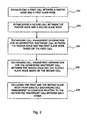
- Fig. 2 shows a flow chart 200 illustrating a first embodiment of a method for providing an asymmetric multipoint call. The method will be explained with reference to the communication network of Fig. 1 .
- the method 200 starts in step 202 by establishing a first call is between master node 10 and first slave node 12.
- the first call is logical connection capable of defining a multipoint network service instance.
- a second call is established between master node 10 and second slave node 14.
- call management information for an asymmetric multipoint call is exchanged between master node 10 and first slave node 12.
- the exchanged call management information comprises an Endpoint Group Identifier (EGI), a Master Node Identifier (MNI), and a Local Call Delimiter (LCD).
- EGI Endpoint Group Identifier
- MNI Master Node Identifier
- LCD Local Call Delimiter
- step 208 call management information for the asymmetric multipoint call is exchanged between master node 10 and second slave node 14 based on the second call.
- the call management information exchanged between master node 10 and second slave node 14 as well comprises EGI, MNI and LCD values for the asymmetric multipoint call.
- step 210 which can also be performed as an initial step, first slave node 12 and second slave node 14 are excluded from directly exchanging call management information relating to the asymmetric multipoint call between each other.
- the call management information is only exchanged via master node 10 between first slave node 12 and second slave node 14.
- the further slave nodes 16 and 18 may also participate in the asymmetric multipoint call and exchange call management information with master node 10. However, no call management information is directly exchanged between slave nodes 12, 14, 16 and 18 bypassing master node 10.
- master node 10 is in charge of the asymmetric multipoint call and has all information regarding the asymmetric multipoint call available. Therefore, efficient control of the asymmetric multipoint call can be provided. Moreover, by using the point-to-point connections 20, 22, 24 and 26 for an asymmetric multipoint call, multipoint services can be efficiently supported. Furthermore, the asymmetric multipoint call concept shown in Figs. 1 and 2 also supports point-to-point calls between two endpoint nodes.
- Fig. 3 shows a schematic block diagram illustrating an embodiment of slave node 12 shown in Fig. 1 .
- Slave node 12 comprises a communication unit 300 and a management unit 302 and is capable of communicating in a communication network supporting DCM features. Further components not shown in Fig. 3 may be included in slave node 12.
- Slave nodes 14, 16 and 18 shown in Fig. 1 may have the same structure.
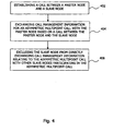
- Fig. 4 shows a flow chart 400 illustrating a second embodiment of a method for providing an asymmetric multipoint call between a plurality of network nodes. The method will be explained with reference to master node 10 and slave nodes 12, 14, 16 and 18 shown in Figs. 1 and 3 .
- step 402 The method starts in step 402 by establishing a call between master node 10 and slave node 12. Further calls for an asymmetric multipoint call are established between master node 10 and slave nodes 14, 16 and 18.
- communication unit 300 of slave node 12 exchanges call management information for the asymmetric multipoint call with master node 10 based on the call established between master node 10 and slave node 12.
- the call management information comprises EGI, MNI and LCD values.
- management unit 302 of slave node 12 excludes slave node 12 from directly exchanging call management information relating to the asymmetric multipoint call with the other slave nodes 14, 16 and 18 participating in the asymmetric multipoint call.
- slave node 12 supports master node 10 in controlling the asymmetric multipoint call.
- the asymmetric multipoint call can be more efficiently controlled.
- Fig. 5 shows a schematic block diagram illustrating an embodiment of master node 10 shown in Fig. 1 .
- Master node 10 is configured to control an asymmetric multipoint call with a plurality of slave nodes in a communication network supporting DCM features and comprises a communication unit 500. Further components not shown in Fig. 5 may be included in master node 10.
- Fig. 6 shows a flowchart 600 illustrating a third embodiment of a method for providing an asymmetric multipoint call between a plurality of network nodes in a communication network. The method will be explained with reference to master node 10 and slave nodes 12, 14, 16 and 18 shown in Figs. 1 , 3 and 5 .
- the method starts in step 602 by establishing a first call between master node 10 and first slave node 12. Thereafter, in step 604, a second call is established between master node 10 and second slave node 14.
- call management information for an asymmetric multipoint call is exchanged between master node 10 and first slave node 12 based on the first call.
- call management information for the asymmetric multipoint call is further exchanged between master node 10 and first slave node 14 based on the second call.
- the call management information comprises EGI, MNI and LCD values. Further calls may be established between master node 10 and slave nodes 16 and 18. Based on these further calls, call management information may be exchanged between master node 10 and slave nodes 16 and 18. However, no call management information is directly exchanged between slave nodes 12, 14, 16 and 18 bypassing master node 10.
- Master node 10 controls the relation between calls supporting the same network service instance.
- multiple calls may identify the same network service instance.
- multipoint services may be efficiently implemented using point-to-multipoint connections.
- master node 10 controls asymmetric multipoint call instances using Call invitation messages and Call Disconnect messages.
- the Call invitation and Call Disconnect messages may be implemented based on Resource Reservation Protocol with Traffic Engineering extensions (RSVP-TE) signalling objects.
- RSVP-TE Resource Reservation Protocol with Traffic Engineering extensions
- master node 10 For inviting slave node 18 to an existing asymmetric multipoint call between master node 10 and slave nodes 12, 14 and 16, master node 10 sends a Call invitation message as a call invitation request to slave node 18.
- Slave node 18 decides whether it accepts or refuses the call invitation request and replies with a call invitation response message. In case slave node 18 accepts the call invitation request, it becomes a slave node within the asymmetric multipoint call between master node 10 and slave nodes 12, 14 and 16. In case slave node 18 refuses the invitation or sends no response to master node 10, slave node 18 does not join the asymmetric multipoint call.
- master node 10 can cause a slave node to leave a call, e.g., slave node 16 to leave the asymmetric multipoint call. If an ongoing network connectivity between master node 10 and slave node 16 exists, slave node 16 can either reject the Call Disconnect request and indicate to master node 10 that a network connectivity is still implemented or it may accept the Call Disconnect request and disconnect active network connections. In case no active network connections exist between master node 10 and slave node 16, slave node 16 may accept the Call Disconnect request. In the case slave nodes 16 rejects the Call Disconnect request, master node 10 may close active network connections and resend the Call Disconnect message.
- an embodiment of an endpoint controlled asymmetric multipoint call will be explained with reference to Fig. 1 .
- This embodiment can be combined with any of the embodiments discussed above.
- the endpoint controlled asymmetric multipoint call concept may be provided additionally or alternatively to the above described master node controlled asymmetric multipoint call concept.
- the endpoint controlled asymmetric multipoint call concept enables a node to join an existing asymmetric multipoint call based on a Call Join message.
- Node 16 intending to join an existing asymmetric multipoint call between master node 10 and slave nodes 12 and 14 sends a Call Join request to master node 10.
- the Call Join message includes EGI, MNI and LCD values for a specific asymmetric multipoint call.
- Master node 10 decides whether it accepts or refuses the Call Join request. Acceptance is signalled to node 16 based on a Call Join Accept message and refusal is signalled to node 16 by a Call Join Refuse message or no response.
- a call identified by the EGI, MNI and LCD values included in the Call Join message is not known to master node 10, it interprets the Call Join message in that node 16 intends to establish a new call.
- a new call may be created in case master node 10 accepts the Call Join request from node 16.
- node 16 establishes the new call, e.g., an asymmetric multipoint call, and becomes the master node for this call.
- the forgoing embodiment is based on identifier matching, i.e., master node 10 assumes that node 16 has sufficient information regarding the EGI, MNI and LCD values identifying the current asymmetric multipoint call available. Therefore, if the EGI, MNI and LCD values transmitted in the Call Join message correspond to the current asymmetric multipoint call, master node 10 automatically treats the Call Join request message as a join request to the current asymmetric multipoint call. Accordingly, if a new call is identified by the EGI, MNI and LCD values included in the Call Join message, master node 10 interprets the Call Join message as a request for establishing a new call.
- node 16 intends to join an existing asymmetric multipoint call between master node 10 and slave nodes 12 and 14 as a slave node.
- node 16 does not have sufficient information regarding the EGI, MNI and LCD values of the existing asymmetric multipoint call.
- node 16 includes arbitrary EGI, MNI and/or LCD values in the Call Join message to be sent to master node 10.
- master node 10 when master node 10 receives the Call Join message from node 16, it cannot determine whether node 16 wants to join the existing asymmetric multipoint call between master node 10 and slave nodes 12 and 14 (however, does not have the actual EGI, MNI and/or LCD values available), or wants to establish a new call.
- This problem may be solved based on explicit indication, in which a one bit flag "Establishing New Call Instance (ENCI)" identifier is added to the Call invitation message and/or the Call Join request message.
- ENCI Establishing New Call Instance
- master node 10 knows that node 16 wants to establish a new call.
- the Call Join message includes an ENCI flag having the value "0”
- master node 10 knows that node 16 wants to join the existing asymmetric multipoint call, however, is not aware of the actual EGI, MNI and/or LCD values.
- a slave node participating in an asymmetric multipoint call may leave the call based on a Call Leave message. For example, slave node 18 sends a Call Leave message to master node 10. Thereafter, master node 10 checks whether slave node 18 is involved in any network connections regarding the asymmetric multipoint call. If this is the case, master node 10 rejects the request. Master node 10 may alternatively cause a disconnection of network connections with slave node 18 by sending a Disconnect a Call message to slave node 18.
- the call management information according to this embodiment does not comprise information on the slave nodes 12, 14, 16 and 18 participating in the asymmetric multipoint call. Therefore, slave nodes 12, 14, 16 and 18 are not aware of other slave nodes 12, 14, 16 and 18 participating in the asymmetric multipoint call. Hence, slave nodes 12, 14, 16 and 18 cannot establish direct network connections between each other, however, only with master node 10.
- the call management information (i.e., the EGI, MNI and LCD values) is extended with a list of slave nodes 12, 14, 16 and 18 participating in the asymmetric multipoint call to extended call management information.
- master node 10 can distribute changes of the list of slave nodes along with the EGI, MNI and LCD values (i.e., the extended call management information) to slave nodes 12, 14, 16 and 18 participating in the asymmetric multipoint call. For example, if master node 10 detects that slave node 16 has disconnected from the current asymmetric multipoint call, it forwards this information to the remaining slave nodes 12, 14 and 18. The remaining slave nodes 12, 14 and 18 can accordingly update its local lists.
- the above defined Call Join message, Call invitation message and Call Leave message are not affected.
- the Call Disconnect message is affected, since master node 10 may not be aware of network connections provided between slave nodes 12, 14, 16 and 18. Such network connections may be provided for communicating other information than call management information between slave nodes 12, 14; 16 and 18. If for example a network connection between slave nodes 12 and 14 exists and master node 10 sends a Call Disconnect message to slave node 12, slave node 12 may refuse the Call Disconnect request and indicate to master node 10 that a network connection still exists. For handling this situation, a Release Connections message is provided. The Release Connections message is sent by master node 10 to slave node 12. Upon receipt of the Release Connections message, slave node 12 disconnects all connections relating to the asymmetric multipoint call. Thereafter, slave node 12 sends a message confirming the connections release to master node 10.
- a node master or slave
- a node can be disconnected from an asymmetric multipoint call if the respective node does not participate in any network connections (i.e., point-to-point or multipoint connections).
- an "Add a Connection to the Call" operation and a "Remove a connection from the Call” operation are provided.
- the Add a Connection to the Call operation establishes a network connection for implementing an asymmetric multipoint call and allocates the network connection to the call.
- the Remove a connection from the Call operation removes a network connection implementing an asymmetric multipoint call from the call. Thereafter, the network connection may be released.
- slave nodes 12, 14, 16 and 18 and master node 10 may stop operation due to failure.
- network connections terminating at the failed slave node are released.
- master node 10 may detect that slave node 14 fails and may send a message encoding this information to the other slave nodes 12, 16 and 18 still participating in the asymmetric multipoint call. This update may be provided based on the State Synchronization procedure described above.
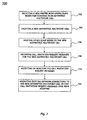
- Fig. 7 shows a flow chart 700 illustrating an embodiment of a method for handling master node failure in case the State Synchronization procedure is implemented. The method may be executed by master node 10 and/or slave nodes 12, 14, 16 and 18 shown in Fig. 1 .
- a new master node is selected among slave nodes 12, 14, 16 and 18 participating in the asymmetric multipoint call. For this, the slave node having a lowest MNI value (i.e., slave node 12) is selected to become the new master node. Since all slave nodes 12, 14, 16 and 18 have a list of slave nodes participating in the asymmetric multipoint call together with the EGI, NMI and LCD values due to the implemented State Synchronization procedure, this selection based on the identifier of the slave node is possible.
- step 704 the new master node 12 creates a new asymmetric multipoint call.
- the new master node 12 invites the other slave nodes 14, 16 and 18 based on Call invitation messages to the new asymmetric multipoint call.
- the identifiers EGI, MNI and LCD of the disrupted asymmetric multipoint call may be embedded in an object transmitted within in the Call invitation messages.
- slave nodes 14, 16 and 18 receive the Call invitation messages including the identifiers EGI, MNI and LCD of the disrupted asymmetric multipoint call.
- slave nodes 14, 16 and 18 accept or refuse the invitation to the new asymmetric multipoint call.
- step 712 network connections belonging to the disrupted asymmetric multipoint call are migrated to the new asymmetric multipoint call. Since changing a connection-to-call assignment of an existing network connection is not possible, the migration may be implemented by signalling of new network connections replacing existing network connections based on a so called "make-beforebreak" concept. Thereby, disruption of data plane connectivity can be prevented.
- Fig. 8 shows a diagram illustrating a further embodiment of a method for providing an asymmetric multipoint call. This embodiment can be combined with any of the embodiments described above.
- the embodiment of Fig. 8 relates to an endpoint controlled asymmetric multipoint call in which a State Synchronization procedure is implemented.
- the communication network schematically shown in Fig. 8 comprises a master node 10, a first slave node 12 and a second slave node 14.
- the communication network may correspond to the communication network of Fig. 1 .
- master node 10 initiates an asymmetric multipoint call procedure. For this, master node 10 determines the EGI, MNI and LCD identifiers for an asymmetric multipoint call. Thereafter, master node 10 invites first slave node 12 with an Invite.req message to the asymmetric multipoint call. First slave node 12 accepts the invitation with an Invite.ack response message. Thereafter, Call Join and State Synchronization are provided. For this, the second slave node 14 requests to join the asymmetric multipoint call with a Join.req message. Master node 10 accepts this request and informs the second slave node 14 of its decision with a Join.ack message.
- the first slave node 12 is informed about the second slave 14 node joining the asymmetric multipoint call with a StateSync.req message which is sent by master node 10 to first slave node 12.
- First slave node 12 acknowledges receipt of this update with a StateSync.ack message.
- the asymmetric multipoint call is established and the network connections belonging to the asymmetric multipoint call are implemented.
- master node 10 wants second slave node 14 to be disconnected from asymmetric multipoint call. For this, master node 10 sends a ReleaseConnections.req message to second slave node 14, which is acknowledged by a ReleaseConnections.ack message to master node 10. Thereafter, a Disconnect.req message is sent by master node 10 to second slave node 14, which is acknowledged by a Disconnect.ack message. Subsequently, state synchronization based on exchanging StateSync.req and StateSync.ack messages between master node 10 and first slave node 12 is provided.
- first slave node 12 also wants to leave the asymmetric multipoint call. Therefore, it sends a Leave.req message to master node 10. Master node 10 acknowledges this request with a Leave.ack message. Subsequent state synchronization is not required, since first slave node 12 is the only remaining slave node of the asymmetric multipoint call.
- EGI, MNI and LCD values are transmitted in call management messages and control messages which are relating to network connections to be assigned to a call.
- embodiments for mapping the identifier values EGI, MNI and LCD to signalling objects are described.
- the identifier values are mapped to bit fields of RSVP-TE signalling objects.
- the first embodiment relates to an embedded identifier option which makes use of asymmetric multipoint calls being implemented based on multipoint connections or multicast trees.
- a signalling concept for multicast trees is described in document IETF/CCAMP RFC-4875 "Extensions to Resource Reservation Protocol - Traffic Engineering (RSVP-TE) for Point-to-Multipoint TE Label Switched Paths (LSPs)" by R. Aggarwal, D. Papadimitriou and S. Yasukawa.
- a one-to-one mapping between the asymmetric multipoint call identifiers and multicast tree identifiers may provided as shown in the following table: Multipoint call Multicast tree identifier Multicast tree object Domain Endpoint group ID Point to multipoint ID Point to multipoint Session 32 bits Master Node ID IPv4 tunnel sender address Point to multipoint Sender Template/flowspec 32 bits Local Call Delimiter Unused 16 bit word Point to multipoint Session 16 bits
- the EGI and the MNI values are assigned to existing fields, while the LCD values are provided in a used 16 bit word of a point-to-multipoint session object. Since the master node corresponds to a router ID of the master node, the RSVP-TE protocol allows this bit field to be transported. Since LCD values are mapped to an undefined 16 bit word of a point-to-multipoint session object, a new version of the object may be required.
- the Multipoint Call Session object has the following structure:
- the further fields may carry connection specific descriptors which are defined by RSVP-TE.
- mapping identifier values EGI, MNI and LCD to RSVP-TE signalling objects is based on a separated identifier option.
- identifiers defined for asymmetric multipoint calls are detached from identifiers relating to connections.
- further protocol objects carrying the identifiers during call management operations and connection assignment operations are introduced.
- a first object introduced for the separated identifier option is a Multipoint Call Session object which is only carrying call identifiers and is only used for call management operations.
- the Multipoint Call Session object has the following structure:
- the Multipoint Call Session object carries EGI and LCD fields, whereas all further fields are set to zero during sending and are ignored during receipt.
- Multipoint Call Sender Template object Another operation introduced according to the separated identifier option is a Multipoint Call Sender Template object.
- the Multipoint Call Sender Template object is defined for call descriptions and is only used for call management operations.
- the Multipoint Call Sender Template object has the following structure:
- the Multipoint Call Sender Template object carries a master node ID identifier having a bit length of 32 bit.
- the other fields of the Multipoint Call Sender Template object have no specific meaning and are set to zero. These fields are also ignored during receiving.
- the Multipoint Call Session object and the Multipoint Call Sender Template object are different for point-to-point and point-to-multipoint LSPs.
- the objects carry different fields and different values are provided in the fields together with different contexts. Therefore, one-to-one matching cannot always be provided.
- an object ASSIGN_TO_CALL for carrying the call identifiers in the control messages of the call implementing LSPs is provided.
- the ASSIGN_TO_CALL object has the following structure:
- the call identifiers are registered. For this, a binary format of 11bbbbbb (where "b" are free bits) and a class type set to "1" are provided. Thereby, the ASSIGN_TO_CALL object can be transparently relayed via intermediate nodes of the communication network.
- a Multipoint Call Slave identifier and an Administration Status object may be used.
- a Multipoint Call Slave identifier having the following structure is provided:
- ENCI flag "E" can be added to the Administration Status object having the following structure:
- the further flags C, T, A and D of the Administration Status object may be implemented as defined in documents IETF/CCAMP RFC-4974, IETF/CCAMP RFC-3471 and IETF/CCAMP RFC-3473.
- RSVP-TE specific procedures for the above explained master controlled and endpoint controlled asymmetric multipoint call messages are explained.
- the messages may be transported within the communication network based on RSVP-TE notify messages, as defined in document IETF/CCAMP RFC-4974. Both the embedded and the separated identifier options are supported, however, different Multipoint Call Session objects and Multipoint Call Sender Template objects may be used.
- the RSVP-TE based implementation may be provided in the communication network shown in Fig. 1 .
- the master node For the Call invitation message, the master node has actual EGI, MNI and LCD values available. The EGI, MNI and LCD values may have been generated previously.
- the master node sends a notify message comprising call related objects.
- the Multipoint Call Session object carries the EGI and LCD values and the Multipoint Call Sender Template object carries the MNI. Other fields of the objects are set to zero.
- the Multipoint Call Slave Identifier object carries the ID of the targeted slave node.
- the objects identifying the old call may be embedded in a Referred Multipoint call instance object.
- the slave node parses the message. Based on the content of the multipoint call slave ID, the slave node determines whether it is the destination of a call invitation request. If this is the case, the slave node decides based on local procedures and policies whether it accepts the call invitation request or not. In accordance with the decision, the slave node answers the request which is encoded in another RSVP-TE notify message.
- the node intending to become a slave node sends a notify message to the master node.
- This is similar to the Call invitation operation, i.e., the C and R bits in the Administration Status object are set to "1".
- the master node ID is the router ID of the destination node, whereas the slave node ID is the router ID of the initiating node.
- the EGI and LCD values are known in advance by the initiator node.
- the master node receives the message and checks whether the ENCI flag E in the Administration Status object is set. If flag E is set to "1", the call request indicates an explicit indication mode in which the master node assumes that a new multipoint call is to be established. If flag E is set to "0", the call request is treated to indicate an implicit indication mode.
- the master node decides whether it accepts or refuses the call request and provides a corresponding response. The response carries the identifier.
- a slave node triggered call disconnection For disconnecting a slave node from a multipoint call based on the Call Disconnect message and for or implementing the Call Leave message, i.e., a slave node triggered call disconnection, signalling based on the Administration Status objects using R, C and D flags can be used.
- the master node synchronizes the state of the slave node by only distributing changes of the call state.
- the master node distributes these changes by embedding the change information in a periodical or a triggered RSVP-TE notify refresh message.
- the notify refresh message refreshes associations between the master node and the slave nodes.
- Further messages describing the call state changes may be transported in an Embedded Call State change object.
- This object may contain the Multipoint Call Slave Identifier object the Administration Status object and all other objects describing the state change, which may be copied from the original message describing the state stage.
- the Embedded Call State Change object may not carry the Multipoint Call Session object and the Multipoint Call Sender Template object, since the identifiers for these objects are the same.
- the same type of Multipoint Call Session objects and Multipoint Call Sender Template objects may be used in both the call management and LSP control messages.
- the objects may also carry all attributes identifying a call instance. Therefore, no other objects need to be signalled during LSP signalling.
- an E-TREE connectivity can be implemented with a single multipoint call in that one multicast tree is signalled and additional multicast trees having only one leaf are established by one node. Accordingly, only the master node can initiate an LSP for a call, since the EGI and MNI values are not interchangeable.
- new RSVP-TE objects are defined for call managing. Furthermore, connection to call assignment is provided with a new object. Therefore, any kind of LSP signalling may be used and backward compatibility is provided. Moreover, an intermediate node does not have to be capable of decoding an ASSIGN_TO_CALL and only has to forward the ASSIGN_TO_CALL object with a class number being larger than 192. Furthermore, signalling LSPs between slave nodes are allowed in case the slave nodes have knowledge about the identifiers of the other slave nodes.
- the master node controlled option with embedded identifiers allows a limited multipoint service support. Route initiated multicast services and rooted multipoint services, (e.g., E-TREE) are supported. In case of E-TREE implementation, if a leaf of the E-TREE wants to join a network service, an additional procedure may be necessary which notifies the master node to extend both the call and the implementing connections.
- the master node controlled option with dedicated identifiers allows using both point-to-multipoint and point-to-point LSP signalling for network connections. An advantage of both master controlled options is the low signalling complexity.
- the nodes are enabled to join the network services, e.g., an E-TREE as a leaf.
- the endpoint controlled option with state synchronization and dedicated identifiers supports multipoint services requiring arbitrary connectivity among the endpoint nodes.
- an E-LAN service can be supported with a single instance.
- the asymmetric multipoint call concept described herein provides a single control plane entity. Thereby, a simplified mechanism for supporting multipoint services is provided. In particular, multiple calls may identify the same network service instance. Moreover, since the master node is in charge of the asymmetric multipoint call and has all information regarding the asymmetric multipoint call available, efficient control of the asymmetric multipoint call can be provided. Furthermore, by using the point-to-point connections for an asymmetric multipoint call, multipoint services can be efficiently supported.
Landscapes
- Engineering & Computer Science (AREA)
- Signal Processing (AREA)
- Computer Networks & Wireless Communication (AREA)
- Multimedia (AREA)
- Telephonic Communication Services (AREA)
Claims (22)
- Verfahren (200) zum Bereitstellen eines asymmetrischen Mehrfachrufes zwischen mehreren Netzknoten (10, 12, 14) in einem Kommunikationsnetz, das Distributed Call and Connection Management (DCM bzw. verteilte Anruf- und Verbindungsverwaltungs)-Funktionen unterstützt und Generalized Multiprotocol Label Switching (GMPLS)-Protokolle verwendet, in denen funktionale Einheiten bezüglich Rufverwaltung und Verbindungsverwaltung in mehreren Netzknoten des Kommunikationsnetzes implementiert sind, wobei der asymmetrische Mehrfachruf einen ersten Ruf aufweist, der zwischen einem Master-Knoten (10) und einem ersten Slave-Knoten (12) aufgebaut wird, und einen zweiten Ruf, der zwischen dem Master-Knoten (10) und einem zweiten Slave-Knoten (14) aufgebaut wird, und verschiedene Daten zwischen dem Master-Knoten (10) und dem ersten Slave-Knoten (12) und zwischen dem Master-Knoten (10) und dem zweiten Slave-Knoten (14) ausgetauscht werden, wobei das Verfahren die folgenden Schritte aufweist:- Austauschen (206) von Rufverwaltungsinformation für den asymmetrischen Mehrfachruf zwischen dem Master-Knoten (10) und dem ersten Slave-Knoten (12) basierend auf dem ersten Ruf;- Austauschen (208) von Rufverwaltungsinformation für den asymmetrischen Mehrfachruf zwischen dem Master-Knoten (10) und dem zweiten Slave-Knoten (14) basierend auf dem zweiten Ruf; und- Ausschließen (210) des ersten (12) und des zweiten (14) Slave-Knoten vom direkten gegenseitigen Austausch von Rufverwaltungsinformation bezüglich des asymmetrischen Mehrfachrufes.
- Verfahren (400) zum Bereitstellen eines asymmetrischen Mehrfachrufes zwischen mehreren Netzknoten (10,12, 14) in einem Kommunikationsnetz, das Distributed Call and Connection Management (DCM)-Funktionen unterstützt und Generalized Multiprotocol Label Switching (GMPLS)-Protokolle verwendet, in denen funktionale Einheiten bezüglich der Rufverwaltung und der Verbindungsverwaltung in mehreren Netzknoten des Kommunikationsnetzes implementiert werden, wobei der asymmetrische Mehrfachruf Rufe aufweist, die zwischen einem Master-Knoten (10) und mehreren Slave-Knoten (12, 14) aufgebaut werden, und verschiedene Daten zwischen dem Master-Knoten (10) und den mehreren Slave-Knoten (12, 14) ausgetauscht werden, wobei das Verfahren die folgenden von einem ersten Slave-Knoten (12) ausgeführten Schritte aufweist:- Austauschen (404) von Rufverwaltungsinformation für den asymmetrischen Mehrfachruf mit dem Master-Knoten (10) basierend auf einem ersten Ruf, der zwischen dem Master-Knoten (10) und dem ersten Slave-Knoten (12) aufgebaut wurde; und- Ausschließen (406) des ersten Slave-Knoten (12) vom direkten Austausch von Rufverwaltungsinformation bezüglich des asymmetrischen Mehrfachrufes mit einem oder mehreren anderen Slave-Knoten (14), die an dem asymmetrischen Mehrfachruf teilnehmen.
- Verfahren nach einem der vorhergehenden Ansprüche, wobei
die Rufverwaltungsinformation Identifizierungsinformation aufweist, die den asymmetrischen Mehrfachruf eindeutig identifiziert. - Verfahren nach Anspruch 3, wobei
die Identifizierungsinformation Information bezüglich wenigstens einem der Netzknoten, die am asymmetrischen Mehrfachruf teilnehmen, bezüglich des Master-Knotens des asymmetrischen Mehrfachrufs und bezüglich des lokalen Identifizierers des asymmetrischen Mehrfachrufs aufweist. - Verfahren nach einem der Ansprüche 3 oder 4, wobei
die Identifizierungsinformation Information bezüglich der am asymmetrischen Mehrfachruf teilnehmenden Slave-Knoten aufweist. - Verfahren gemäß einem der Ansprüche 3 bis 5, das weiterhin den folgenden Schritt aufweist:- Empfangen von Änderungsbenachrichtigungen der Identifizierungsinformation vom Master-Knoten (10) an dem wenigstens ersten Slave-Knoten (12).
- Verfahren nach einem der Ansprüche 3 bis 6, das weiterhin die folgenden wenigstens vom ersten Slave-Knoten (12) ausgeführten Schritte aufweist:- Empfangen von Ausfallinformation bezüglich eines Ausfalls des Master-Knoten (10); und- Senden als Reaktion auf die empfangene Ausfallinformation von Rufeinladungsnachrichten, die die Identifizierungsinformation enthalten, welche den asymmetrischen Mehrfachruf eindeutig identifizieren, an an dem asymmetrischen Mehrfachruf teilnehmende Netzknoten (12, 14).
- Verfahren nach einem der vorhergehenden Ansprüche, das weiterhin die folgenden Schritte aufweist:- Bestimmen, ob der erste Slave-Knoten (12) an Netzverbindungen mit anderen Netzknoten teilnimmt, die den asymmetrischen Mehrfachruf implementieren; und- Verlassen, durch wenigstens den ersten Slave-Knoten (12), des asymmetrischen Mehrfachrufes, falls keine Teilnahme bestimmt wird.
- Verfahren nach einem der vorhergehenden Ansprüche, das weiterhin den folgenden Schritt aufweist:- Senden einer Rufbeitrittsanforderungsnachricht an den Master-Knoten (10), wobei die Nachricht einen Identifizierer aufweist, der angibt, ob ein vom aktuell bereitgestellten asymmetrischen Mehrfachruf unabhängiger Ruf aufgebaut werden soll.
- Verfahren (600) zum Bereitstellen eines asymmetrischen Mehrfachrufes zwischen mehreren Netzknoten (10, 12, 14) in einem Kommunikationsnetz, das Distributed Call and Connection Management (DCM)-Funktionen unterstützt und Generalized Multiprotocol Label Switching (GMPLS)-Protokolle verwendet, in denen funktionale Einheiten bezüglich der Rufverwaltung und der Verbindungsverwaltung in mehreren Netzknoten des Kommunikationsnetzes implementiert werden, wobei der asymmetrische Mehrfachruf aufweist, dass ein erster Ruf zwischen einem Master-Knoten (10) und einem ersten Slave-Knoten (12) aufgebaut wird, dass ein zweiter Ruf zwischen dem Master-Knoten (10) und einem zweiten Slave-Knoten (14) aufgebaut wird, dass die ersten (12) und zweiten (14) Slave-Knoten vom direkten gegenseitigen Austausch von Rufverwaltungsinformation bezüglich eines asymmetrischen Mehrfachrufs ausgeschlossen werden, und dass verschiedene Daten zwischen dem Master-Knoten (10) und dem ersten Slave-Knoten (12) und zwischen dem Master-Knoten (10) dem zweiten Slave-Knoten (14) ausgetauscht werden, wobei das Verfahren die folgenden vom Master-Knoten (10) durchgeführten Schritte aufweist:- Austauschen (606) von Rufverwaltungsinformation für den asymmetrischen Mehrfachruf mit dem ersten Slave-Knoten (12) basierend auf dem ersten Ruf; und- Austauschen (608) von Rufverwaltungsinformation für den asymmetrischen Mehrfachruf mit dem zweiten Slave-Knoten (14) basierend auf dem zweiten Ruf.
- Verfahren nach einem der Ansprüche 1 oder 10, das weiterhin die folgenden vom Master-Knoten ausgeführten Schritte aufweist:- Empfangen einer Rufbeitrittsanforderungsnachricht von einem dritten Slave-Knoten (16), wobei die Nachricht Identifizierungsinformation aufweist, die einen bestimmten asymmetrischen Mehrfachruf eindeutig identifiziert;- Bestimmen, ob die empfangene Rufbeitrittsanforderungsnachricht zum aktuell bereitgestellten asymmetrischen Mehrfachruf gehört; und- Ermöglichen, dass der dritte Slave-Knoten (16) dem aktuell bereitgestellten asymmetrischen Mehrfachruf beitritt, wenn bestimmt wurde, dass die empfangene Rufbeitrittsanforderungsnachricht zu dem aktuell bereitgestellten asymmetrischen Mehrfachruf gehört.
- Verfahren nach Anspruch 11, das weiterhin den folgenden Schritt aufweist:- Aufbau eines dritten Rufes, der unabhängig vom aktuell bereitgestellten asymmetrischen Mehrfachruf ist, zwischen dem Master-Knoten (10) und dem dritten Slave-Knoten (16), wenn bestimmt wurde, dass die empfangene Rufbeitrittsanforderungsnachricht nicht zu dem aktuell bereitgestellten asymmetrischen Mehrfachruf gehört.
- Verfahren nach einem der Ansprüche 1 oder 10 bis 12, das weiterhin den folgenden Schritt aufweist:- Senden einer Rufeinladungsnachricht an einen vierten Slave-Knoten (18), wobei die Nachricht Identifizierungsinformation aufweist, die den aktuell bereitgestellten asymmetrischen Mehrfachruf eindeutig identifiziert, und einen Identifizierer, der angibt, ob ein von dem aktuell bereitgestellten asymmetrischen Mehrfachruf unabhängiger Ruf aufgebaut werden soll.
- Verfahren nach einem der Ansprüche 1 oder 10 bis 13, das weiterhin den folgenden Schritt aufweist:- Berichten von Änderungen der Identifizierungsinformation, die den symmetrischen Mehrfachruf für den ersten (12) und zweiten (14) Slave-Knoten eindeutig identifiziert.
- Verfahren nach einem der Ansprüche 1 oder 10 bis 14, das weiterhin die folgenden vom Master-Knoten ausgeführten Schritte aufweist:- Senden einer Ruftrennungsnachricht, um den ersten Ruf zum ersten Slave-Knoten (12) zu trennen;- Empfangen einer Nachricht der Ablehnung der Ruftrennung von dem ersten Slave-Knoten (12); und- Senden als Reaktion auf die Nachricht der Ablehnung der Ruftrennung einer Verbindungsfreigabenachricht an den ersten Slave-Knoten (12), wobei die Verbindungsfreigabenachricht den ersten Slave-Knoten (12) veranlasst, alle Verbindungen zu anderen Netzknoten zu trennen, die sich auf den asymmetrischen Mehrfachruf beziehen.
- Computerprogrammprodukt mit Programmcodeabschnitten zum Durchführen aller Verfahrensschritte nach einem der Ansprüche 1 bis 15, wenn das Computerprogrammprodukt auf einer oder mehreren Komponenten des Kommunikationsnetzes ausgeführt wird.
- Computerprogrammprodukt nach Anspruch 16, das auf einem computerlesbaren Aufzeichnungsmedium gespeichert ist.
- Kommunikationsnetz, das Distributed Call and Connection Management (DCM)-Funktionen unterstützt und Generalized Multiprotocol Label Switching (GMPLS)-Protokolle verwendet, in denen funktionale Einheiten bezüglich der Rufverwaltung und der Verbindungsverwaltung in mehreren Netzknoten (10, 12, 14) des Kommunikationsnetzes implementiert sind, das aufweist- einen ersten Slave-Knoten (12), der dazu ausgebildet ist, von dem direkten Austausch von Rufverwaltungsinformation bezüglich eines asymmetrischen Mehrfachrufs mit einem anderen Slave-Knoten, der am asymmetrischen Mehrfachruf teilnimmt, ausgeschlossen zu sein;- einen zweiten Slave-Knoten (14), der dazu ausgebildet ist, von dem direkten Austausch von Rufverwaltungsinformation bezüglich eines asymmetrischen Mehrfachrufs mit einem anderen Slave-Knoten, der am asymmetrischen Mehrfachruf teilnimmt, ausgeschlossen zu sein; und- einen Master-Knoten (10), der dazu ausgebildet ist, Rufverwaltungsinformation für einen asymmetrischen Mehrfachruf zwischen dem Master-Knoten (10) und dem ersten Slave-Knoten (12) basierend auf einem ersten Ruf auszutauschen, und Rufverwaltungsinformation für den asymmetrischen Mehrfachruf zwischen dem Master-Knoten (10) und dem zweiten Slave-Knoten (14) basierend auf einem zweiten Ruf auszutauschen, wobei der asymmetrische Mehrfachruf den ersten Ruf und den zweiten Ruf aufweist, und verschiedene Daten zwischen dem Master-Knoten (10) und dem ersten Slave-Knoten (12) und zwischen dem Master-Knoten (10) und dem zweiten Slave-Knoten (14) ausgetauscht werden.
- Slave-Knoten (12), der dazu ausgebildet ist, an einem asymmetrischen Mehrfachruf zwischen mehreren Netzknoten in einem Kommunikationsnetz, das Distributed Call and Connection Management (DCM)-Funktionen unterstützt und Generalized Multiprotocol Label Switching (GMPLS)-Protokolle verwendet, teilzunehmen, in denen funktionale Einheiten bezüglich der Rufverwaltung und der Verbindungsverwaltung in mehreren Netzknoten des Kommunikationsnetzes implementiert sind, wobei Mehrfachrufe zwischen einem Master-Knoten (10) und mehreren Slave-Knoten (12, 14) aufgebaut werden, wobei der Slave-Knoten (12) aufweist- eine Kommunikationseinheit (300), die dazu ausgebildet ist, Rufverwaltungsinformation für den asymmetrischen Mehrfachruf mit dem Master-Knoten (10) basierend auf einem ersten Ruf, der zwischen dem Master-Knoten (10) und dem Slave-Knoten (12) aufgebaut wurde, auszutauschen; und- eine Verwaltungseinheit (302), die dazu ausgebildet ist, den Slave-Knoten (12) vom direkten Austausch von Rufverwaltungsinformation bezüglich des asymmetrischen Mehrfachrufs mit einem oder mehreren Slave-Knoten (14) auszuschließen, die am asymmetrischen Mehrfachruf teilnehmen, wobei der asymmetrische Mehrfachruf die mehreren Rufe aufweist und verschiedene Daten zwischen dem Master-Knoten (10) und den mehreren Slave-Knoten (12, 14) ausgetauschten werden.
- Slave-Knoten (12) nach Anspruch 19, wobei
die Rufverwaltungsinformation Information aufweist, die den asymmetrischen Mehrfachruf eindeutig identifiziert und die Kommunikationseinheit dazu ausgebildet ist, Änderungen an der Identifizierungsinformation von dem Master-Knoten (10) zu erhalten. - Master-Knoten (10), der dazu ausgebildet ist, in einem asymmetrischen Mehrfachruf zwischen mehreren Netzknoten in einem Kommunikationsnetz teilzunehmen, das Distributed Call and Connection Management (DCM)-Funktionen unterstützt und Generalized Multiprotocol Label Switching (GMPLS)-Protokolle verwendet, in denen funktionale Einheiten bezüglich der Rufverwaltung und der Verbindungsverwaltung in mehreren Netzknoten des Kommunikationsnetzes implementiert werden, wobei ein erster Ruf zwischen dem Master-Knoten (10) und einem ersten Slave-Knoten (12) aufgebaut wird, ein zweiter Ruf zwischen dem Master-Knoten (10) und einem zweiten Slave-Knoten (14) aufgebaut wird, und der erste (12) und zweite (14) Slave-Knoten vom direkten gegenseitigen Austausch von Rufverwaltungsinformation bezüglich des asymmetrischen Mehrfachrufes ausgeschlossen werden, wobei der Master-Knoten (10) aufweist- eine Kommunikationseinheit (500), die dazu ausgebildet ist, Rufverwaltungsinformation für den asymmetrischen Mehrfachruf mit dem ersten Slave-Knoten (12) basierend auf dem ersten Ruf auszutauschen, und um Rufverwaltungsinformation für den asymmetrischen Mehrfachruf mit dem zweiten Slave-Knoten (14) basierend auf dem zweiten Ruf auszutauschen, wobei der asymmetrische Mehrfachruf den ersten Ruf und den zweiten Ruf aufweist, und verschiedene Daten zwischen dem Master-Knoten (10) und dem ersten Slave-Knoten (12) und zwischen dem Master-Knoten (10) und dem zweiten Slave-Knoten (14) ausgetauscht werden.
- Master-Knoten (10) nach Anspruch 21, der weiterhin aufweist- eine Empfangseinheit, die dazu ausgebildet ist, eine Rufbeitrittsanforderungsnachricht von einem dritten Slave-Knoten (16) zu empfangen, wobei die Nachricht Information aufweist, die einen bestimmten asymmetrischen Mehrfachruf eindeutig identifiziert;- eine Bestimmungseinheit, die dazu ausgebildet ist, zu bestimmen, ob die empfangene Rufbeitrittsanforderungsnachricht zu dem aktuell bereitgestellten asymmetrischen Mehrfachruf gehört; und- eine Verwaltungseinheit, die dazu ausgebildet ist, dem dritten Slave-Knoten (16) den Beitritt zu dem aktuell bereitgestellten asymmetrischen Mehrfachruf zu ermöglichen, wenn bestimmt wurde, dass die empfangene Rufbeitrittsanforderungsnachricht zu dem aktuell bereitgestellten asymmetrischen Mehrfachruf gehört.
Applications Claiming Priority (1)
| Application Number | Priority Date | Filing Date | Title |
|---|---|---|---|
| PCT/EP2009/005191 WO2011006520A1 (en) | 2009-07-16 | 2009-07-16 | Technique for providing an asymmetric multipoint call between a plurality of network nodes |
Publications (2)
| Publication Number | Publication Date |
|---|---|
| EP2454887A1 EP2454887A1 (de) | 2012-05-23 |
| EP2454887B1 true EP2454887B1 (de) | 2013-09-11 |
Family
ID=41786090
Family Applications (1)
| Application Number | Title | Priority Date | Filing Date |
|---|---|---|---|
| EP09777250.3A Not-in-force EP2454887B1 (de) | 2009-07-16 | 2009-07-16 | Verfahren zur bereitstellung von einem asymmetrischen mehrfachruf zwischen mehreren netzknoten |
Country Status (3)
| Country | Link |
|---|---|
| US (1) | US8717948B2 (de) |
| EP (1) | EP2454887B1 (de) |
| WO (1) | WO2011006520A1 (de) |
Cited By (1)
| Publication number | Priority date | Publication date | Assignee | Title |
|---|---|---|---|---|
| WO2018014613A1 (en) * | 2016-07-19 | 2018-01-25 | Zhejiang Dahua Technology Co., Ltd. | Systems and methods for migrating data |
Families Citing this family (50)
| Publication number | Priority date | Publication date | Assignee | Title |
|---|---|---|---|---|
| US9769016B2 (en) | 2010-06-07 | 2017-09-19 | Brocade Communications Systems, Inc. | Advanced link tracking for virtual cluster switching |
| US9270486B2 (en) | 2010-06-07 | 2016-02-23 | Brocade Communications Systems, Inc. | Name services for virtual cluster switching |
| US9716672B2 (en) | 2010-05-28 | 2017-07-25 | Brocade Communications Systems, Inc. | Distributed configuration management for virtual cluster switching |
| US8867552B2 (en) | 2010-05-03 | 2014-10-21 | Brocade Communications Systems, Inc. | Virtual cluster switching |
| US9608833B2 (en) * | 2010-06-08 | 2017-03-28 | Brocade Communications Systems, Inc. | Supporting multiple multicast trees in trill networks |
| US9628293B2 (en) | 2010-06-08 | 2017-04-18 | Brocade Communications Systems, Inc. | Network layer multicasting in trill networks |
| US9806906B2 (en) | 2010-06-08 | 2017-10-31 | Brocade Communications Systems, Inc. | Flooding packets on a per-virtual-network basis |
| US9807031B2 (en) | 2010-07-16 | 2017-10-31 | Brocade Communications Systems, Inc. | System and method for network configuration |
| US9736085B2 (en) | 2011-08-29 | 2017-08-15 | Brocade Communications Systems, Inc. | End-to end lossless Ethernet in Ethernet fabric |
| US9699117B2 (en) | 2011-11-08 | 2017-07-04 | Brocade Communications Systems, Inc. | Integrated fibre channel support in an ethernet fabric switch |
| US9450870B2 (en) | 2011-11-10 | 2016-09-20 | Brocade Communications Systems, Inc. | System and method for flow management in software-defined networks |
| US8995272B2 (en) | 2012-01-26 | 2015-03-31 | Brocade Communication Systems, Inc. | Link aggregation in software-defined networks |
| US9742693B2 (en) | 2012-02-27 | 2017-08-22 | Brocade Communications Systems, Inc. | Dynamic service insertion in a fabric switch |
| US9154416B2 (en) | 2012-03-22 | 2015-10-06 | Brocade Communications Systems, Inc. | Overlay tunnel in a fabric switch |
| US8755385B2 (en) | 2012-05-03 | 2014-06-17 | Itron, Inc. | Authentication using DHCP services in mesh networks |
| US9591525B2 (en) * | 2012-05-03 | 2017-03-07 | Itron Global Sarl | Efficient device handover/migration in mesh networks |
| US9374301B2 (en) | 2012-05-18 | 2016-06-21 | Brocade Communications Systems, Inc. | Network feedback in software-defined networks |
| US10277464B2 (en) | 2012-05-22 | 2019-04-30 | Arris Enterprises Llc | Client auto-configuration in a multi-switch link aggregation |
| US9401872B2 (en) | 2012-11-16 | 2016-07-26 | Brocade Communications Systems, Inc. | Virtual link aggregations across multiple fabric switches |
| US9548926B2 (en) | 2013-01-11 | 2017-01-17 | Brocade Communications Systems, Inc. | Multicast traffic load balancing over virtual link aggregation |
| US9350680B2 (en) | 2013-01-11 | 2016-05-24 | Brocade Communications Systems, Inc. | Protection switching over a virtual link aggregation |
| US9413691B2 (en) | 2013-01-11 | 2016-08-09 | Brocade Communications Systems, Inc. | MAC address synchronization in a fabric switch |
| US9565099B2 (en) | 2013-03-01 | 2017-02-07 | Brocade Communications Systems, Inc. | Spanning tree in fabric switches |
| WO2014145750A1 (en) | 2013-03-15 | 2014-09-18 | Brocade Communications Systems, Inc. | Scalable gateways for a fabric switch |
| US9699001B2 (en) | 2013-06-10 | 2017-07-04 | Brocade Communications Systems, Inc. | Scalable and segregated network virtualization |
| US20150063330A1 (en) * | 2013-08-30 | 2015-03-05 | Qualcomm Incorporated | Aggregation of data packets for multiple stations |
| US9806949B2 (en) | 2013-09-06 | 2017-10-31 | Brocade Communications Systems, Inc. | Transparent interconnection of Ethernet fabric switches |
| US9912612B2 (en) | 2013-10-28 | 2018-03-06 | Brocade Communications Systems LLC | Extended ethernet fabric switches |
| US9548873B2 (en) | 2014-02-10 | 2017-01-17 | Brocade Communications Systems, Inc. | Virtual extensible LAN tunnel keepalives |
| US10581758B2 (en) | 2014-03-19 | 2020-03-03 | Avago Technologies International Sales Pte. Limited | Distributed hot standby links for vLAG |
| US10476698B2 (en) | 2014-03-20 | 2019-11-12 | Avago Technologies International Sales Pte. Limited | Redundent virtual link aggregation group |
| US10063473B2 (en) | 2014-04-30 | 2018-08-28 | Brocade Communications Systems LLC | Method and system for facilitating switch virtualization in a network of interconnected switches |
| US9800471B2 (en) | 2014-05-13 | 2017-10-24 | Brocade Communications Systems, Inc. | Network extension groups of global VLANs in a fabric switch |
| US10616108B2 (en) | 2014-07-29 | 2020-04-07 | Avago Technologies International Sales Pte. Limited | Scalable MAC address virtualization |
| US9807007B2 (en) | 2014-08-11 | 2017-10-31 | Brocade Communications Systems, Inc. | Progressive MAC address learning |
| US9699029B2 (en) | 2014-10-10 | 2017-07-04 | Brocade Communications Systems, Inc. | Distributed configuration management in a switch group |
| US9626255B2 (en) | 2014-12-31 | 2017-04-18 | Brocade Communications Systems, Inc. | Online restoration of a switch snapshot |
| US9628407B2 (en) | 2014-12-31 | 2017-04-18 | Brocade Communications Systems, Inc. | Multiple software versions in a switch group |
| US9942097B2 (en) | 2015-01-05 | 2018-04-10 | Brocade Communications Systems LLC | Power management in a network of interconnected switches |
| US10003552B2 (en) | 2015-01-05 | 2018-06-19 | Brocade Communications Systems, Llc. | Distributed bidirectional forwarding detection protocol (D-BFD) for cluster of interconnected switches |
| US10038592B2 (en) | 2015-03-17 | 2018-07-31 | Brocade Communications Systems LLC | Identifier assignment to a new switch in a switch group |
| US9807005B2 (en) | 2015-03-17 | 2017-10-31 | Brocade Communications Systems, Inc. | Multi-fabric manager |
| US10579406B2 (en) | 2015-04-08 | 2020-03-03 | Avago Technologies International Sales Pte. Limited | Dynamic orchestration of overlay tunnels |
| US10439929B2 (en) | 2015-07-31 | 2019-10-08 | Avago Technologies International Sales Pte. Limited | Graceful recovery of a multicast-enabled switch |
| US10171303B2 (en) | 2015-09-16 | 2019-01-01 | Avago Technologies International Sales Pte. Limited | IP-based interconnection of switches with a logical chassis |
| US9912614B2 (en) | 2015-12-07 | 2018-03-06 | Brocade Communications Systems LLC | Interconnection of switches based on hierarchical overlay tunneling |
| US10237090B2 (en) | 2016-10-28 | 2019-03-19 | Avago Technologies International Sales Pte. Limited | Rule-based network identifier mapping |
| WO2019171979A1 (ja) * | 2018-03-06 | 2019-09-12 | Smc株式会社 | 無線通信システム、スレーブ無線装置及びマスタ無線装置 |
| CN108919756B (zh) * | 2018-06-25 | 2020-07-28 | 首都师范大学 | 一种cps节点功能处理方法的加载与调用方法 |
| CN114421997B (zh) * | 2021-12-14 | 2023-09-29 | 江苏芯云电子科技有限公司 | 一种电力线载波混合组网方法、装置及系统 |
Family Cites Families (5)
| Publication number | Priority date | Publication date | Assignee | Title |
|---|---|---|---|---|
| JP2001077924A (ja) * | 1999-09-01 | 2001-03-23 | Fujitsu Ltd | 多地点通信システム及びその方法 |
| GB0012410D0 (en) | 2000-05-23 | 2000-07-12 | Koninkl Philips Electronics Nv | Radio system and apparatus for, and method of, multicast communication |
| US6785246B2 (en) * | 2001-01-09 | 2004-08-31 | Telefonaktiebolaget L M Ericsson (Publ) | Multi-party conferencing method |
| US7953006B2 (en) * | 2006-02-09 | 2011-05-31 | Nokia Corporation | Handling multiple point-to-multipoint services |
| CN101542445B (zh) * | 2006-12-05 | 2012-10-10 | 高通股份有限公司 | 零单点故障负载平衡器的设备及方法 |
-
2009
- 2009-07-16 EP EP09777250.3A patent/EP2454887B1/de not_active Not-in-force
- 2009-07-16 US US13/382,030 patent/US8717948B2/en active Active
- 2009-07-16 WO PCT/EP2009/005191 patent/WO2011006520A1/en not_active Ceased
Cited By (3)
| Publication number | Priority date | Publication date | Assignee | Title |
|---|---|---|---|---|
| WO2018014613A1 (en) * | 2016-07-19 | 2018-01-25 | Zhejiang Dahua Technology Co., Ltd. | Systems and methods for migrating data |
| US10922004B2 (en) | 2016-07-19 | 2021-02-16 | Zhejiang Dahua Technology Co., Ltd. | Systems and methods for migrating data records |
| US11620067B2 (en) | 2016-07-19 | 2023-04-04 | Zhejiang Dahua Technology Co., Ltd. | Systems and methods for migrating data |
Also Published As
| Publication number | Publication date |
|---|---|
| US20120170491A1 (en) | 2012-07-05 |
| EP2454887A1 (de) | 2012-05-23 |
| US8717948B2 (en) | 2014-05-06 |
| WO2011006520A1 (en) | 2011-01-20 |
Similar Documents
| Publication | Publication Date | Title |
|---|---|---|
| EP2454887B1 (de) | Verfahren zur bereitstellung von einem asymmetrischen mehrfachruf zwischen mehreren netzknoten | |
| US10476793B2 (en) | Multicast flow overlay using registration over a reliable transport | |
| CN1326369C (zh) | 网络拓扑构成方法及节点 | |
| JP5653912B2 (ja) | マルチキャスト・グループ管理のための方法及び装置 | |
| US8676888B2 (en) | Method for multi-terminal session, and communication system and related device thereof | |
| US7787457B2 (en) | Label assigning method, label replacing method and label switching router | |
| CN101355441B (zh) | 一种配置操作管理维护属性的方法、系统及设备 | |
| CN101605138A (zh) | 文件传输方法及终端 | |
| CN101686179A (zh) | 链路状态发布信息的传输方法、节点和点对点网络 | |
| CN102469082B (zh) | 一种路径切换方法及装置、系统 | |
| CN101335695A (zh) | 点到多点标签交换路径的头节点保护方法、装置和设备 | |
| EP2541847A1 (de) | Verfahren zur herstellung eines assoziierten bidirektionalen label-switching-weges und system dafür | |
| CN108023832A (zh) | 信息发送方法、装置及系统 | |
| US9191312B2 (en) | Method and system for implementing PW control bit capability negotiation | |
| EP2439876B1 (de) | Verfahren und vorrichtung für multicasting-anfragen, zur verarbeitung von multicasting-anfragen und zur unterstützung in besagten prozessen | |
| CN101453414B (zh) | 点到多点标签交换路径的头节点保护方法、系统和设备 | |
| CN102857536B (zh) | 对等网络中实现数据备份及迁移的方法及系统 | |
| CN100359877C (zh) | 一种链路类型的发现方法 | |
| CN101192959B (zh) | 一种自动交换光网络组播业务连接的恢复方法 | |
| WO2019001487A1 (zh) | 一种路径数据的删除方法、一种消息转发方法和装置 | |
| CN100450030C (zh) | 一种实现呼叫服务等级到承载呼叫的连接的映射方法 | |
| CN108023810A (zh) | 连接能力的通告方法及装置 | |
| CN100542167C (zh) | 基于igrs协议的主从设备组之间无线路由实现方法 | |
| CN104901824A (zh) | Openflow辅助通道的配置方法及装置 | |
| WO2022141440A1 (en) | Method and network element for network redundancy |
Legal Events
| Date | Code | Title | Description |
|---|---|---|---|
| PUAI | Public reference made under article 153(3) epc to a published international application that has entered the european phase |
Free format text: ORIGINAL CODE: 0009012 |
|
| 17P | Request for examination filed |
Effective date: 20120111 |
|
| AK | Designated contracting states |
Kind code of ref document: A1 Designated state(s): AT BE BG CH CY CZ DE DK EE ES FI FR GB GR HR HU IE IS IT LI LT LU LV MC MK MT NL NO PL PT RO SE SI SK SM TR |
|
| DAX | Request for extension of the european patent (deleted) | ||
| GRAP | Despatch of communication of intention to grant a patent |
Free format text: ORIGINAL CODE: EPIDOSNIGR1 |
|
| RAP1 | Party data changed (applicant data changed or rights of an application transferred) |
Owner name: TELEFONAKTIEBOLAGET LM ERICSSON (PUBL) |
|
| GRAS | Grant fee paid |
Free format text: ORIGINAL CODE: EPIDOSNIGR3 |
|
| GRAA | (expected) grant |
Free format text: ORIGINAL CODE: 0009210 |
|
| AK | Designated contracting states |
Kind code of ref document: B1 Designated state(s): AT BE BG CH CY CZ DE DK EE ES FI FR GB GR HR HU IE IS IT LI LT LU LV MC MK MT NL NO PL PT RO SE SI SK SM TR |
|
| REG | Reference to a national code |
Ref country code: GB Ref legal event code: FG4D |
|
| REG | Reference to a national code |
Ref country code: CH Ref legal event code: EP |
|
| REG | Reference to a national code |
Ref country code: AT Ref legal event code: REF Ref document number: 632180 Country of ref document: AT Kind code of ref document: T Effective date: 20130915 |
|
| REG | Reference to a national code |
Ref country code: IE Ref legal event code: FG4D |
|
| REG | Reference to a national code |
Ref country code: DE Ref legal event code: R096 Ref document number: 602009018759 Country of ref document: DE Effective date: 20131107 |
|
| PG25 | Lapsed in a contracting state [announced via postgrant information from national office to epo] |
Ref country code: LT Free format text: LAPSE BECAUSE OF FAILURE TO SUBMIT A TRANSLATION OF THE DESCRIPTION OR TO PAY THE FEE WITHIN THE PRESCRIBED TIME-LIMIT Effective date: 20130911 Ref country code: CY Free format text: LAPSE BECAUSE OF FAILURE TO SUBMIT A TRANSLATION OF THE DESCRIPTION OR TO PAY THE FEE WITHIN THE PRESCRIBED TIME-LIMIT Effective date: 20130828 Ref country code: HR Free format text: LAPSE BECAUSE OF FAILURE TO SUBMIT A TRANSLATION OF THE DESCRIPTION OR TO PAY THE FEE WITHIN THE PRESCRIBED TIME-LIMIT Effective date: 20130911 Ref country code: NO Free format text: LAPSE BECAUSE OF FAILURE TO SUBMIT A TRANSLATION OF THE DESCRIPTION OR TO PAY THE FEE WITHIN THE PRESCRIBED TIME-LIMIT Effective date: 20131211 Ref country code: SE Free format text: LAPSE BECAUSE OF FAILURE TO SUBMIT A TRANSLATION OF THE DESCRIPTION OR TO PAY THE FEE WITHIN THE PRESCRIBED TIME-LIMIT Effective date: 20130911 |
|
| REG | Reference to a national code |
Ref country code: NL Ref legal event code: VDEP Effective date: 20130911 |
|
| REG | Reference to a national code |
Ref country code: AT Ref legal event code: MK05 Ref document number: 632180 Country of ref document: AT Kind code of ref document: T Effective date: 20130911 |
|
| REG | Reference to a national code |
Ref country code: LT Ref legal event code: MG4D |
|
| PG25 | Lapsed in a contracting state [announced via postgrant information from national office to epo] |
Ref country code: GR Free format text: LAPSE BECAUSE OF FAILURE TO SUBMIT A TRANSLATION OF THE DESCRIPTION OR TO PAY THE FEE WITHIN THE PRESCRIBED TIME-LIMIT Effective date: 20131212 Ref country code: SI Free format text: LAPSE BECAUSE OF FAILURE TO SUBMIT A TRANSLATION OF THE DESCRIPTION OR TO PAY THE FEE WITHIN THE PRESCRIBED TIME-LIMIT Effective date: 20130911 Ref country code: FI Free format text: LAPSE BECAUSE OF FAILURE TO SUBMIT A TRANSLATION OF THE DESCRIPTION OR TO PAY THE FEE WITHIN THE PRESCRIBED TIME-LIMIT Effective date: 20130911 Ref country code: LV Free format text: LAPSE BECAUSE OF FAILURE TO SUBMIT A TRANSLATION OF THE DESCRIPTION OR TO PAY THE FEE WITHIN THE PRESCRIBED TIME-LIMIT Effective date: 20130911 |
|
| PG25 | Lapsed in a contracting state [announced via postgrant information from national office to epo] |
Ref country code: CY Free format text: LAPSE BECAUSE OF FAILURE TO SUBMIT A TRANSLATION OF THE DESCRIPTION OR TO PAY THE FEE WITHIN THE PRESCRIBED TIME-LIMIT Effective date: 20130911 Ref country code: BE Free format text: LAPSE BECAUSE OF FAILURE TO SUBMIT A TRANSLATION OF THE DESCRIPTION OR TO PAY THE FEE WITHIN THE PRESCRIBED TIME-LIMIT Effective date: 20130911 |
|
| PG25 | Lapsed in a contracting state [announced via postgrant information from national office to epo] |
Ref country code: CZ Free format text: LAPSE BECAUSE OF FAILURE TO SUBMIT A TRANSLATION OF THE DESCRIPTION OR TO PAY THE FEE WITHIN THE PRESCRIBED TIME-LIMIT Effective date: 20130911 Ref country code: EE Free format text: LAPSE BECAUSE OF FAILURE TO SUBMIT A TRANSLATION OF THE DESCRIPTION OR TO PAY THE FEE WITHIN THE PRESCRIBED TIME-LIMIT Effective date: 20130911 Ref country code: SK Free format text: LAPSE BECAUSE OF FAILURE TO SUBMIT A TRANSLATION OF THE DESCRIPTION OR TO PAY THE FEE WITHIN THE PRESCRIBED TIME-LIMIT Effective date: 20130911 Ref country code: IS Free format text: LAPSE BECAUSE OF FAILURE TO SUBMIT A TRANSLATION OF THE DESCRIPTION OR TO PAY THE FEE WITHIN THE PRESCRIBED TIME-LIMIT Effective date: 20140111 Ref country code: NL Free format text: LAPSE BECAUSE OF FAILURE TO SUBMIT A TRANSLATION OF THE DESCRIPTION OR TO PAY THE FEE WITHIN THE PRESCRIBED TIME-LIMIT Effective date: 20130911 Ref country code: RO Free format text: LAPSE BECAUSE OF FAILURE TO SUBMIT A TRANSLATION OF THE DESCRIPTION OR TO PAY THE FEE WITHIN THE PRESCRIBED TIME-LIMIT Effective date: 20130911 |
|
| PG25 | Lapsed in a contracting state [announced via postgrant information from national office to epo] |
Ref country code: ES Free format text: LAPSE BECAUSE OF FAILURE TO SUBMIT A TRANSLATION OF THE DESCRIPTION OR TO PAY THE FEE WITHIN THE PRESCRIBED TIME-LIMIT Effective date: 20130911 Ref country code: PL Free format text: LAPSE BECAUSE OF FAILURE TO SUBMIT A TRANSLATION OF THE DESCRIPTION OR TO PAY THE FEE WITHIN THE PRESCRIBED TIME-LIMIT Effective date: 20130911 Ref country code: AT Free format text: LAPSE BECAUSE OF FAILURE TO SUBMIT A TRANSLATION OF THE DESCRIPTION OR TO PAY THE FEE WITHIN THE PRESCRIBED TIME-LIMIT Effective date: 20130911 |
|
| REG | Reference to a national code |
Ref country code: DE Ref legal event code: R097 Ref document number: 602009018759 Country of ref document: DE |
|
| PG25 | Lapsed in a contracting state [announced via postgrant information from national office to epo] |
Ref country code: PT Free format text: LAPSE BECAUSE OF FAILURE TO SUBMIT A TRANSLATION OF THE DESCRIPTION OR TO PAY THE FEE WITHIN THE PRESCRIBED TIME-LIMIT Effective date: 20140113 |
|
| PLBE | No opposition filed within time limit |
Free format text: ORIGINAL CODE: 0009261 |
|
| STAA | Information on the status of an ep patent application or granted ep patent |
Free format text: STATUS: NO OPPOSITION FILED WITHIN TIME LIMIT |
|
| 26N | No opposition filed |
Effective date: 20140612 |
|
| PG25 | Lapsed in a contracting state [announced via postgrant information from national office to epo] |
Ref country code: IT Free format text: LAPSE BECAUSE OF FAILURE TO SUBMIT A TRANSLATION OF THE DESCRIPTION OR TO PAY THE FEE WITHIN THE PRESCRIBED TIME-LIMIT Effective date: 20130911 |
|
| REG | Reference to a national code |
Ref country code: DE Ref legal event code: R097 Ref document number: 602009018759 Country of ref document: DE Effective date: 20140612 |
|
| PG25 | Lapsed in a contracting state [announced via postgrant information from national office to epo] |
Ref country code: DK Free format text: LAPSE BECAUSE OF FAILURE TO SUBMIT A TRANSLATION OF THE DESCRIPTION OR TO PAY THE FEE WITHIN THE PRESCRIBED TIME-LIMIT Effective date: 20130911 |
|
| REG | Reference to a national code |
Ref country code: DE Ref legal event code: R119 Ref document number: 602009018759 Country of ref document: DE |
|
| PG25 | Lapsed in a contracting state [announced via postgrant information from national office to epo] |
Ref country code: LU Free format text: LAPSE BECAUSE OF FAILURE TO SUBMIT A TRANSLATION OF THE DESCRIPTION OR TO PAY THE FEE WITHIN THE PRESCRIBED TIME-LIMIT Effective date: 20140716 |
|
| REG | Reference to a national code |
Ref country code: CH Ref legal event code: PL |
|
| REG | Reference to a national code |
Ref country code: IE Ref legal event code: MM4A |
|
| REG | Reference to a national code |
Ref country code: FR Ref legal event code: ST Effective date: 20150331 |
|
| PG25 | Lapsed in a contracting state [announced via postgrant information from national office to epo] |
Ref country code: LI Free format text: LAPSE BECAUSE OF NON-PAYMENT OF DUE FEES Effective date: 20140731 Ref country code: CH Free format text: LAPSE BECAUSE OF NON-PAYMENT OF DUE FEES Effective date: 20140731 Ref country code: DE Free format text: LAPSE BECAUSE OF NON-PAYMENT OF DUE FEES Effective date: 20150203 |
|
| REG | Reference to a national code |
Ref country code: DE Ref legal event code: R119 Ref document number: 602009018759 Country of ref document: DE Effective date: 20150203 |
|
| PG25 | Lapsed in a contracting state [announced via postgrant information from national office to epo] |
Ref country code: FR Free format text: LAPSE BECAUSE OF NON-PAYMENT OF DUE FEES Effective date: 20140731 |
|
| PG25 | Lapsed in a contracting state [announced via postgrant information from national office to epo] |
Ref country code: IE Free format text: LAPSE BECAUSE OF NON-PAYMENT OF DUE FEES Effective date: 20140716 |
|
| PG25 | Lapsed in a contracting state [announced via postgrant information from national office to epo] |
Ref country code: SM Free format text: LAPSE BECAUSE OF FAILURE TO SUBMIT A TRANSLATION OF THE DESCRIPTION OR TO PAY THE FEE WITHIN THE PRESCRIBED TIME-LIMIT Effective date: 20130911 Ref country code: MC Free format text: LAPSE BECAUSE OF FAILURE TO SUBMIT A TRANSLATION OF THE DESCRIPTION OR TO PAY THE FEE WITHIN THE PRESCRIBED TIME-LIMIT Effective date: 20130911 |
|
| PG25 | Lapsed in a contracting state [announced via postgrant information from national office to epo] |
Ref country code: BG Free format text: LAPSE BECAUSE OF FAILURE TO SUBMIT A TRANSLATION OF THE DESCRIPTION OR TO PAY THE FEE WITHIN THE PRESCRIBED TIME-LIMIT Effective date: 20130911 Ref country code: MT Free format text: LAPSE BECAUSE OF FAILURE TO SUBMIT A TRANSLATION OF THE DESCRIPTION OR TO PAY THE FEE WITHIN THE PRESCRIBED TIME-LIMIT Effective date: 20130911 |
|
| PG25 | Lapsed in a contracting state [announced via postgrant information from national office to epo] |
Ref country code: HU Free format text: LAPSE BECAUSE OF FAILURE TO SUBMIT A TRANSLATION OF THE DESCRIPTION OR TO PAY THE FEE WITHIN THE PRESCRIBED TIME-LIMIT; INVALID AB INITIO Effective date: 20090716 Ref country code: TR Free format text: LAPSE BECAUSE OF FAILURE TO SUBMIT A TRANSLATION OF THE DESCRIPTION OR TO PAY THE FEE WITHIN THE PRESCRIBED TIME-LIMIT Effective date: 20130911 |
|
| PG25 | Lapsed in a contracting state [announced via postgrant information from national office to epo] |
Ref country code: MK Free format text: LAPSE BECAUSE OF FAILURE TO SUBMIT A TRANSLATION OF THE DESCRIPTION OR TO PAY THE FEE WITHIN THE PRESCRIBED TIME-LIMIT Effective date: 20130911 |
|
| PGFP | Annual fee paid to national office [announced via postgrant information from national office to epo] |
Ref country code: GB Payment date: 20220727 Year of fee payment: 14 |
|
| GBPC | Gb: european patent ceased through non-payment of renewal fee |
Effective date: 20230716 |
|
| PG25 | Lapsed in a contracting state [announced via postgrant information from national office to epo] |
Ref country code: GB Free format text: LAPSE BECAUSE OF NON-PAYMENT OF DUE FEES Effective date: 20230716 |