EP2455178A1 - Drehwerkzeug für reibschweissungsoperationen - Google Patents
Drehwerkzeug für reibschweissungsoperationen Download PDFInfo
- Publication number
- EP2455178A1 EP2455178A1 EP10799832A EP10799832A EP2455178A1 EP 2455178 A1 EP2455178 A1 EP 2455178A1 EP 10799832 A EP10799832 A EP 10799832A EP 10799832 A EP10799832 A EP 10799832A EP 2455178 A1 EP2455178 A1 EP 2455178A1
- Authority
- EP
- European Patent Office
- Prior art keywords
- friction stir
- stir welding
- rotary tool
- prove pin
- prove
- Prior art date
- Legal status (The legal status is an assumption and is not a legal conclusion. Google has not performed a legal analysis and makes no representation as to the accuracy of the status listed.)
- Withdrawn
Links
- 238000003466 welding Methods 0.000 title claims abstract description 137
- 238000003756 stirring Methods 0.000 title claims abstract description 98
- 230000006835 compression Effects 0.000 claims abstract description 45
- 238000007906 compression Methods 0.000 claims abstract description 45
- 239000000463 material Substances 0.000 claims description 12
- 238000005299 abrasion Methods 0.000 abstract description 5
- 229910000831 Steel Inorganic materials 0.000 description 11
- 239000010959 steel Substances 0.000 description 11
- 238000005480 shot peening Methods 0.000 description 8
- 238000010586 diagram Methods 0.000 description 7
- 238000000034 method Methods 0.000 description 7
- 230000007423 decrease Effects 0.000 description 5
- 229910001092 metal group alloy Inorganic materials 0.000 description 4
- 230000003247 decreasing effect Effects 0.000 description 3
- 229910000838 Al alloy Inorganic materials 0.000 description 2
- 229910000881 Cu alloy Inorganic materials 0.000 description 2
- 229910000861 Mg alloy Inorganic materials 0.000 description 2
- 229910001069 Ti alloy Inorganic materials 0.000 description 2
- 238000011156 evaluation Methods 0.000 description 2
- 238000005259 measurement Methods 0.000 description 2
- 239000007769 metal material Substances 0.000 description 2
- 238000012986 modification Methods 0.000 description 2
- 230000004048 modification Effects 0.000 description 2
- 240000008042 Zea mays Species 0.000 description 1
- 235000005824 Zea mays ssp. parviglumis Nutrition 0.000 description 1
- 235000002017 Zea mays subsp mays Nutrition 0.000 description 1
- 230000015572 biosynthetic process Effects 0.000 description 1
- 238000007664 blowing Methods 0.000 description 1
- 235000005822 corn Nutrition 0.000 description 1
- 230000000694 effects Effects 0.000 description 1
- 238000009661 fatigue test Methods 0.000 description 1
- 238000005243 fluidization Methods 0.000 description 1
- 230000012447 hatching Effects 0.000 description 1
- 230000006698 induction Effects 0.000 description 1
- 230000001678 irradiating effect Effects 0.000 description 1
- 238000002844 melting Methods 0.000 description 1
- 230000008018 melting Effects 0.000 description 1
- 229910052751 metal Inorganic materials 0.000 description 1
- 239000002184 metal Substances 0.000 description 1
- 230000003647 oxidation Effects 0.000 description 1
- 238000007254 oxidation reaction Methods 0.000 description 1
- 239000000126 substance Substances 0.000 description 1
- 238000009864 tensile test Methods 0.000 description 1
- 239000011800 void material Substances 0.000 description 1
Images


Classifications
-
- B—PERFORMING OPERATIONS; TRANSPORTING
- B23—MACHINE TOOLS; METAL-WORKING NOT OTHERWISE PROVIDED FOR
- B23K—SOLDERING OR UNSOLDERING; WELDING; CLADDING OR PLATING BY SOLDERING OR WELDING; CUTTING BY APPLYING HEAT LOCALLY, e.g. FLAME CUTTING; WORKING BY LASER BEAM
- B23K20/00—Non-electric welding by applying impact or other pressure, with or without the application of heat, e.g. cladding or plating
- B23K20/12—Non-electric welding by applying impact or other pressure, with or without the application of heat, e.g. cladding or plating the heat being generated by friction; Friction welding
- B23K20/122—Non-electric welding by applying impact or other pressure, with or without the application of heat, e.g. cladding or plating the heat being generated by friction; Friction welding using a non-consumable tool, e.g. friction stir welding
-
- B—PERFORMING OPERATIONS; TRANSPORTING
- B23—MACHINE TOOLS; METAL-WORKING NOT OTHERWISE PROVIDED FOR
- B23K—SOLDERING OR UNSOLDERING; WELDING; CLADDING OR PLATING BY SOLDERING OR WELDING; CUTTING BY APPLYING HEAT LOCALLY, e.g. FLAME CUTTING; WORKING BY LASER BEAM
- B23K20/00—Non-electric welding by applying impact or other pressure, with or without the application of heat, e.g. cladding or plating
- B23K20/12—Non-electric welding by applying impact or other pressure, with or without the application of heat, e.g. cladding or plating the heat being generated by friction; Friction welding
- B23K20/122—Non-electric welding by applying impact or other pressure, with or without the application of heat, e.g. cladding or plating the heat being generated by friction; Friction welding using a non-consumable tool, e.g. friction stir welding
- B23K20/1245—Non-electric welding by applying impact or other pressure, with or without the application of heat, e.g. cladding or plating the heat being generated by friction; Friction welding using a non-consumable tool, e.g. friction stir welding characterised by the apparatus
- B23K20/1255—Tools therefor, e.g. characterised by the shape of the probe
-
- B—PERFORMING OPERATIONS; TRANSPORTING
- B23—MACHINE TOOLS; METAL-WORKING NOT OTHERWISE PROVIDED FOR
- B23K—SOLDERING OR UNSOLDERING; WELDING; CLADDING OR PLATING BY SOLDERING OR WELDING; CUTTING BY APPLYING HEAT LOCALLY, e.g. FLAME CUTTING; WORKING BY LASER BEAM
- B23K26/00—Working by laser beam, e.g. welding, cutting or boring
- B23K26/352—Working by laser beam, e.g. welding, cutting or boring for surface treatment
- B23K26/356—Working by laser beam, e.g. welding, cutting or boring for surface treatment by shock processing
-
- C—CHEMISTRY; METALLURGY
- C21—METALLURGY OF IRON
- C21D—MODIFYING THE PHYSICAL STRUCTURE OF FERROUS METALS; GENERAL DEVICES FOR HEAT TREATMENT OF FERROUS OR NON-FERROUS METALS OR ALLOYS; MAKING METAL MALLEABLE, e.g. BY DECARBURISATION OR TEMPERING
- C21D1/00—General methods or devices for heat treatment, e.g. annealing, hardening, quenching or tempering
- C21D1/06—Surface hardening
- C21D1/09—Surface hardening by direct application of electrical or wave energy; by particle radiation
-
- C—CHEMISTRY; METALLURGY
- C21—METALLURGY OF IRON
- C21D—MODIFYING THE PHYSICAL STRUCTURE OF FERROUS METALS; GENERAL DEVICES FOR HEAT TREATMENT OF FERROUS OR NON-FERROUS METALS OR ALLOYS; MAKING METAL MALLEABLE, e.g. BY DECARBURISATION OR TEMPERING
- C21D10/00—Modifying the physical properties by methods other than heat treatment or deformation
- C21D10/005—Modifying the physical properties by methods other than heat treatment or deformation by laser shock processing
-
- B—PERFORMING OPERATIONS; TRANSPORTING
- B23—MACHINE TOOLS; METAL-WORKING NOT OTHERWISE PROVIDED FOR
- B23K—SOLDERING OR UNSOLDERING; WELDING; CLADDING OR PLATING BY SOLDERING OR WELDING; CUTTING BY APPLYING HEAT LOCALLY, e.g. FLAME CUTTING; WORKING BY LASER BEAM
- B23K2101/00—Articles made by soldering, welding or cutting
- B23K2101/20—Tools
Definitions
- the present invention relates to a rotary tool for friction stir welding used for subjecting workpieces to be connected made from metal materials such as aluminum alloy, magnesium alloy, copper alloy, and titanium alloy to friction stir welding, and particularly to a rotary tool for friction stir welding having an excellent durability by which a high-quality friction stir welding can be performed.
- workpieces to be connected made from metal materials such as aluminum alloy, magnesium alloy, copper alloy, and titanium alloy are connected with each other by a method including a mechanical bonding by use of a bolt or a rivet, or resistance spot welding, arc welding, or gas welding.
- the resistance spot welding, arc welding, gas welding and the like are widely used since products obtained thereby have lighter weight, the process numbers are smaller, and the devices are relatively simple, compared to compared to the mechanical bonding by use of bolts or rivets.
- the parts to be connected are heated almost to melting temperatures of the materials. Therefore, it is possible that the workpieces are thermally affected to have connection failure in various ways due to thermal deformation, hardening, residual stress, brittleness, or oxidation.
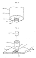
- Fig. 8 is a perspective view for showing an end portion of a rotary tool for friction stir welding as an embodiment, which is to be used for the friction stir welding.
- Fig. 9 is a diagram for showing the friction stir welding method.
- a rotary tool 100 for friction stir welding has a column shape having a shoulder portion 101 in the form of a column at an end.
- a prove pin 102 is protruded from an end surface 101a of the shoulder portion 101.
- a screw part 102a is prepared around the outer periphery at the end of the prove pin 102.
- the prove pin 102 which is protruded from the end surface 101a of the shoulder portion 101, is pressed into an interface Wa between workpieces to be welded (welding workpieces) W which are adjacent to each other, with the rotary drive apparatus 105 being driven.
- the end surface 101a of the shoulder portion 101 is brought into contact with the surface of the workpieces.
- the rotary tool 100 for friction stir welding is moved along the interface Wa between the welding workpieces W.
- the workpieces are connected with each other along the interface Wa.
- the welding workpieces W are subjected to plastic fluidization by the heat generated by friction between the shoulder portion 101/ the prove pin 102 which rotate at a high speed and the welding workpieces W.
- the welding workpieces W in the fluidized state are stirred at the interface Wa by the screw part 102a provided around the outer periphery of the prove pin 102. Thereafter, the portion is cooled to connect the welding workpieces W to each other at the interface.
- the prove pin 102 When the welding workpieces W is fluidized by heat of friction obtained by the rotary tool 100 for friction stir welding being rotated at a high speed, the prove pin 102 being pressed into the interface Wa between the welding workpieces, and the end surface 101a of the shoulder portion 101 contacting the welding workpieces W, the fluidized workpieces may fused to the shoulder portion 101 and the prove pin 102. In such a case, the resistance to stirring becomes larger, which can be a reason for damaging the prove pin. Moreover, when the shoulder portion 101 and the prove pin 102 are exposed to a high temperature, prove pin 102 is largely abraded, and decreases the strength. There is a concern that the prove pin 102, under repetitions application of tension and compression load, is subjected to buckling or breakage, and that the interface Wa between the welded workpieces W is thermally deformed.
- the rotary tool for friction stir welding is designed to have a shaft with an increased diameter and a stress concentration part with an increased curvature, and a material with a high strength is chosen for the rotary tool for friction stir welding.
- the rotary tool with above-mentioned modification has shortcomings, which requires a large cost and time.
- the joint characteristics by the rotary tool may be affected by the modification.
- Patent Literature 1 proposes a rotary tool for friction stir welding wherein abrasion or breakage/damages on the shoulder portion and the prove pin is minimized and the thermal influence on the welding workpieces is restricted.
- the rotary tool for friction stir welding disclosed in Patent Literature 1 includes a prove pin or a shoulder portion prepared from WC-based ultrahard metal alloy comprising 5 to 18 parts by weight of Co, which is configured to contact the welding workpieces.
- This rotary tool for friction stir welding is rotated at a high speed, the prove pin is pressed into the interface between the welding workpieces, with the end surface of the shoulder portion being contacted with the welding workpieces W. Then, the welding workpieces are plastically fluidized by heat of friction, and hence the welding workpieces are connected to each other.
- the prove pin and the shoulder portion prepared from the WC-based ultrahard metal alloy have small toughness, even with an excellent abrasion resistance, which is concerned about being damaged by the repetitious application of tension and compression load during the use.
- the rotary tool for friction stir welding having the prove pin and the shoulder portion prepared from the WC-based ultrahard metal alloy can be costly manufactured, and hence the products which has been connected by using the rotary tool for friction stir welding can be also expensive.
- the prove pin or the shoulder portion especially the screw part formed around the outer periphery of the prove pin at the free end thereof is affected, and the surface profile accuracy is lowered. Due to the decrease in the surface profile accuracy, the friction stir resistance between the prove pin/the end surface of the shoulder portion and the welding workpieces can be increased and the joint characteristics can be decreased, when the workpieces are connected.
- the residual compression stress is extremely shallowly applied by the shot peening, and it is difficult to maintain the residual compression stress sufficient to improve fatigue characteristics. Further, since steel balls cannot be brown precisely to a small area by shot peening, it is difficult to treat a rotary tool with the shot peening, which is for friction stir welding having a small prove pin which requires a good surface profile accuracy.
- pulse laser peening was developed, as a method for imparting residual compression stress to a region nearby the surface of the metal substance, recently. It is possible to control a pulse laser beam irradiation spot at a high accuracy, compared to shot peening. Namely, the pulse laser peening is appropriately used for selectively imparting residual compression stress to a small area. Further, the pulse laser peening is applicable to mechanical parts which have a small surface profile change by the use and which requires a good surface profile accuracy. By the pulse laser peening, it is possible to impart a residual compression stress more deeply, or control the depth of the residual compression stress, by adjusting the condition for irradiating the pulse laser beam such as pulse energy, spot size, pulse irradiation number of the like.
- It is therefore an object of the present invention is to provide a rotary tool for friction stir welding having excellent abrasion resistance and durability, and excellent joint characteristics.
- the above-mentioned object is solved by the invention as claimed in Claim 1, that is a rotary tool for friction stir welding comprising a shoulder portion, and a prove pin protruded from an end surface of the shoulder portion, the prove pin having a screw part around the outer periphery at the side of the free end.
- the prove pin is rotated is pressed into an interface between workpieces to be welded to each other, moved along the interface, and the workpieces to be welded is subjected to friction stir welding at the interface.
- the rotary tool for friction stir welding is characterized in that the outer periphery of the prove pin has been treated by pulse laser peening.
- the prove pin can maintain the surface profile accuracy because the surface profile change is small.
- the pulse laser peening makes it possible to impart the residual compression stress and the increased rigidity deeply to the prove pin. Therefore, it is possible to restrict the crack generation applied to the prove pin, which repetitiously repeat tension and compression stress by the friction stir welding. Hence, the durability of the prove pin is largely improved with the buckling and damages being restricted.
- the invention as claimed in Claim 2 is characterized in that the outer periphery of the prove pin, which is in the rotary tool for friction welding as claimed in Claim 1, has a connection linked to the end surface of the shoulder portion, the pulse laser peening has been applied to a base side region extending from the connection to the screw part.
- the base side region of the prove pin to which tension and compression stress are repeatedly and intensively applied at the friction stir welding, is treated by the above-mentioned pulse laser peening. Therefore, particularly the base side region of the prove pin to which residual compression stress is intensively imparted maintains the toughness, and the damages due to the buckling or thermal deformation of the prove pin are restricted. As a result, the durability of the prove pin is greatly improved.
- the invention as claimed in Claim 3 is characterized in that the pulse laser peening imparts a residual compression stress to the base side region of the prove pin, which is greater than the tensile stress and is smaller than the compressive yield stress applied to the rotary tool for friction stir welding at a maximum temperature during the use, in the rotary tool for friction stir welding as claimed in Claim 1 or 2.
- the residual compression stress applied by the pulse laser peening is controlled to be greater than the tensile stress and smaller than the compressive yield stress applied to the rotary tool for friction stir welding at a maximum temperature during the use.
- pulse laser peeing is applied to the prove pin to which tension or compression stress is repeatedly imparted in the friction stir welding. Because of the treatment, the surface rigidity and the toughness of the prove pin are maintained, the damages from buckling or thermal deformation are restricted, and the durability of the prove pin is largely improved. Moreover, excellent joint characteristics can be obtained, without damaging the surface profile accuracy of the prove pin.
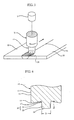
- Fig. 1 is a schematic side view of a rotary tool for friction stir welding as an embodiment of the present invention
- Fig. 2 is a perspective view of portion A in Fig. 1
- Fig. 3 is a cross-section viewed at I-I line in Fig. 2 .
- Fig. 1 shows that the rotary tool 10 for friction stir welding is driven by a rotary drive apparatus such as an induction motor (not shown) to rotate around an axis Z.
- the rotary tool 10 is in the form of a column made of a steel for a hot working tool.
- the rotary tool 10 has a shoulder portion 11 in the form of a column at the end thereof.
- a shoulder pin 20 is formed on an end surface 13 of the shoulder portion 11, which protrudes from the center of the end surface 13 and extends along the axis Z.
- Figs. 2 and 3 show that the end surface 13 of the shoulder portion 11 is in the form of a reversed corn having a center concaved in the direction of the base part. From the most deeply concaved center part, a prove pin 20 extends to its end along the axis Z. A round corner 14 smoothly extending from an outer periphery 12 of the shoulder portion 11 to the end surface 13 is in the form of an arc. In other words, a so-called corner R is formed. Moreover, a connection 15 through which the end surface 13 extend to the base part of the prove pin 20 is also in the form of arc. Namely, a so-called corner R is formed.
- the prove pin 20 is in the form of a column.
- the prove pin 20 has a base side region 22 extending from the outer periphery which has a cross section in the form of a perfect circle, and a free end region 23 having a spiral-shaped screw part 23 a.
- the shoulder portion 11 and the prove pin 20 to which tension and compression stress are repeatedly applied under use, particular the surface of the base side region 22 extending from the connection 15 to the screw part 23a are treated with pulse laser peening, in the present embodiment.
- the connection 15 is a part integral with the end surface 13 of the shoulder portion 11 which receives intensive stress application.
- the pulse laser peening is applied to a surface of the base side region 22 (shown by hatching in Fig. 2 ) in the prove pin 20 including the connection 15 linked to the end surface 13 of the shoulder portion 11 of the rotating rotary tool 10 of friction stir welding, for instance, by rotatingly driving the rotary tool 10 for friction stir welding around the axis Z.
- Fig. 4 is a magnification of an essential part, which shows that the pulse laser beam is converged and irradiated to the above-mentioned surface.
- the pulse laser peening is carried out with beam sports S being shifted in the direction X, i.e., from a base of the prove pin 20 to an end 24 thereof.
- the beam sports S are created so as to be superimposed one on another by applying a pulse laser beam to the prove pin with the scanning in the direction Y.
- the adjacent beam sports S are arranged to be superimposed with each other also in the direction X.
- the irradiation of the pulse laser beam is superimposed on the surface of the end side range 22 of the prove pin 20 including the connection 15 linked to the free end 13 of the shoulder portion 11. Consequently, residual compression stress is imparted to the surface of the base side region 22 of the prove pin 20 to increase the fatigue strength of the surface.
- the prove pin 20 including the connection 15 maintains an excellent surface profile accuracy.
- a desired depth of the residual compression stress can be securely maintained.
- the depth H of the residual compression stress 25% of the diameter D of the prove pin 20 H ⁇ D/4
- the surface rigidity of the prove pin 20 including the connection 15 extending from the end surface 13 of the shoulder portion 11 is sufficiently obtained, and the toughness thereof can be maintained.
- the residual compression stress imparted by the pulse laser beam irradiation with taking into account the decrease of the strength of the rotary tool 10 for friction stir welding.
- the strength of the rotary tool 10 decreases when the temperature thereof increases due to the friction stir welding.
- the prove pin 20 of the rotary tool 10 for friction stir welding arrives at the interface Wa, the welding workpieces W are heated and softened by the heat of friction between the rotating prove pin 20 and the workpieces W. Thus, the prove pin 20 is inserted to the workpieces.
- the prove pin 20 is inserted to the workpieces W by the level where the corner 14 of the shoulder portion 11 in the prove pin contacts the surface of the welding workpieces W.
- the rotating prove pin 20 makes the interface Wa of the welding workpieces W plastically fluidized.
- the screw part 23a provided on the prove pin 20 stirs the thus fluidized welding workpieces W.
- a plastically fluidized area is formed in the interface Wa of the welding workpieces W.
- the rotary tool 10 for friction stir welding is moved along the interface Wa of the welding workpieces W in the longitudinal direction of the interface, thereby sequentially connecting the welding workpieces W at the interface Wa.
- the fluidized welding workpieces W are stirred by the screw part 23a formed around the outer periphery of the prove pin 20 at the free end.
- the screw part 23a is formed to have a reversed screw flight, with respect to the rotational direction of the rotary tool 10 for friction stir welding. Therefore, the fluidized workpieces W are further pressed by the function of the screw part 23a.
- the end surface 13 of the shoulder portion 11 is configured to be concaved from the outer periphery side to the center where the prove pin 20 is provided. Accordingly, the fluidized welding workpieces W are restricted to overflow the interface Wa to outer areas. Accordingly, the welding workpieces W are connected with each other uniformly at the interface Wa without void formation.
- the pulse laser peening is carried out with respect to the base side region 22 of the prove pin 20 including the connection 15 linked to the end surface 13 of the shoulder portion 11 by using the rotary tool 10 for friction stir welding,
- the rotary tool 10 for friction stir welding By the operation, residual compression stress is applied to the base side region without damaging the surface profile of the end surface 13 of the shoulder portion 11 and that of the prove pin 20 including the connection 15 linked to the end surface 13. Therefore, when the welding workpieces W is subjected to friction stir welding along the interface Wa, the welding workpieces W is protected from being adhered to the prove pin 20 or end surface 13 of the shoulder portion 11. Further, the abrasion of the prove pin 20 or the shoulder portion 11 is decreased.
- the base side range 22 of the prove pin 20 including the part 15 linked to the end surface 13 of the shoulder portion 11 maintains the surface rigidity and the toughness. Further, the damages from the buckling and the thermal deformation of the shoulder portion 11 are restricted, to largely increase the durability of the prove pin 20.
- pulse laser peening was applied only to the base part region 22 of the prove pin including the connection 15 linked to the end surface 13 of the shoulder portion 11, to impart the residual stress to the base side region 22.
- an extremely small surface profile change takes place at the screw part 23a. Namely, it is possible to maintain the surface profile accuracy of the entire prove pin 20 including the screw part 23 a.
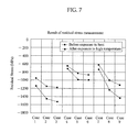
- pulse laser peening treatment was applied to the base side region of the prove pin including a part extending from the end surface of the shoulder potion of the rotary tool for friction stir welding.
- the residual compression stress of the rotary tool was measured before exposure to a high temperature and under exposure to the high temperature.
- Shape of the rotary tool for friction stir welding is a diagram for showing an essential part of the rotary tool which includes parts corresponding to those in Fig. 3 having common reference numerals with the figure.
- the diameter D of the prove pin 20 extending from the center of the end surface 13 of the shoulder portion 11 is 2 mm, and the length L from the end surface 13 to an end 24 is 5 mm.
- Region subjected to pulse laser peening treatment Pulse laser peening was applied to the base side region 22 of the prove pin 20 including the connection 15 linked to the end surface 13 of the shoulder portion 11, with the rotary tool 10 for friction stir welding being rotary driven.
- Materials The materials for the rotary tool 20 for friction stir welding are shown in Table 1.
- the rotary tool 10 for friction stir welding is made of a steel for hot working tool having mechanical characteristics shown in Table 1, i.e., a steel for hot working tool having Young's modulus: 210,000 N/mm 2 , tensile strength: 2,650 N/mm 2 , 0.2% proof stress: 1,960 N/mm 2 , elongation: 4%, reduction: 13%.
Landscapes
- Engineering & Computer Science (AREA)
- Chemical & Material Sciences (AREA)
- Mechanical Engineering (AREA)
- Physics & Mathematics (AREA)
- Optics & Photonics (AREA)
- Thermal Sciences (AREA)
- Crystallography & Structural Chemistry (AREA)
- Materials Engineering (AREA)
- Metallurgy (AREA)
- Organic Chemistry (AREA)
- Plasma & Fusion (AREA)
- Pressure Welding/Diffusion-Bonding (AREA)
Applications Claiming Priority (2)
| Application Number | Priority Date | Filing Date | Title |
|---|---|---|---|
| JP2009165228A JP5654219B2 (ja) | 2009-07-14 | 2009-07-14 | 摩擦攪拌接合用回転ツール |
| PCT/JP2010/061827 WO2011007774A1 (ja) | 2009-07-14 | 2010-07-13 | 摩擦攪拌接合用回転ツール |
Publications (2)
| Publication Number | Publication Date |
|---|---|
| EP2455178A1 true EP2455178A1 (de) | 2012-05-23 |
| EP2455178A4 EP2455178A4 (de) | 2017-08-02 |
Family
ID=43449381
Family Applications (1)
| Application Number | Title | Priority Date | Filing Date |
|---|---|---|---|
| EP10799832.0A Withdrawn EP2455178A4 (de) | 2009-07-14 | 2010-07-13 | Drehwerkzeug für reibschweissungsoperationen |
Country Status (6)
| Country | Link |
|---|---|
| US (1) | US20120318848A1 (de) |
| EP (1) | EP2455178A4 (de) |
| JP (1) | JP5654219B2 (de) |
| KR (1) | KR20120054005A (de) |
| CN (1) | CN102470480A (de) |
| WO (1) | WO2011007774A1 (de) |
Cited By (1)
| Publication number | Priority date | Publication date | Assignee | Title |
|---|---|---|---|---|
| EP2801433A3 (de) * | 2013-05-10 | 2015-06-24 | Kanefusa Kabushiki Kaisha | Verfahren zur Herstellung von Schneidwerkzeugen |
Families Citing this family (16)
| Publication number | Priority date | Publication date | Assignee | Title |
|---|---|---|---|---|
| US9095927B2 (en) * | 2011-08-19 | 2015-08-04 | Nippon Light Metal Company, Ltd. | Friction stir welding method |
| JP5949071B2 (ja) * | 2012-04-03 | 2016-07-06 | 新日鐵住金株式会社 | 摩擦攪拌接合工具及び異質部材の摩擦攪拌接合方法 |
| JP2014094409A (ja) | 2012-10-10 | 2014-05-22 | Nippon Light Metal Co Ltd | 伝熱板の製造方法及び摩擦攪拌接合方法 |
| JP6048079B2 (ja) * | 2012-11-08 | 2016-12-21 | 三菱マテリアル株式会社 | 高抗折力で耐折損性にすぐれた切削工具用wc基超硬合金製線材 |
| WO2015053258A1 (ja) * | 2013-10-07 | 2015-04-16 | 新日鉄住金エンジニアリング株式会社 | 摩擦撹拌接合工具、及び積層材の接合方法 |
| JP6344690B2 (ja) * | 2014-08-28 | 2018-06-20 | 三菱重工エンジニアリング株式会社 | 摩擦撹拌接合用ツール、及び摩擦撹拌接合装置 |
| NL2018981B1 (en) * | 2017-05-26 | 2018-12-07 | Univ Johannesburg Witwatersrand | Method and system for improving the surface fracture toughness of brittle materials, and a cutting tool produced by such method |
| JP2019107665A (ja) * | 2017-12-18 | 2019-07-04 | 日本軽金属株式会社 | 液冷ジャケットの製造方法 |
| FR3075675B1 (fr) * | 2017-12-22 | 2020-01-03 | Constellium Issoire | Outil pour realiser une soudure par friction malaxage |
| JP7024573B2 (ja) * | 2018-04-20 | 2022-02-24 | 日本軽金属株式会社 | 伝熱板の製造方法及び摩擦攪拌接合方法 |
| WO2019235295A1 (ja) * | 2018-06-06 | 2019-12-12 | 国立大学法人大阪大学 | 摩擦攪拌接合用ツール及び摩擦攪拌接合方法 |
| JP7323135B2 (ja) * | 2018-10-15 | 2023-08-08 | 国立大学法人大阪大学 | 摩擦攪拌接合用ツール部材およびそれを用いた摩擦攪拌接合方法 |
| GB201918891D0 (en) | 2019-12-19 | 2020-02-05 | Element Six Uk Ltd | Friction stir welding using a PCBN-based tool |
| JP2021133385A (ja) * | 2020-02-26 | 2021-09-13 | 株式会社東芝 | レーザピーニング施工方法およびレーザピーニング施工システム |
| KR102628488B1 (ko) * | 2020-09-25 | 2024-01-24 | 단국대학교 산학협력단 | 초음파 프로브 및 이의 제조방법 |
| CN112719817A (zh) * | 2021-02-02 | 2021-04-30 | 铜陵学院 | 一种激光熔覆螺旋形耐磨条纹涂层的分体式搅拌摩擦焊搅拌头及其加工方法 |
Family Cites Families (14)
| Publication number | Priority date | Publication date | Assignee | Title |
|---|---|---|---|---|
| WO2001005549A2 (en) * | 1999-07-19 | 2001-01-25 | The Regents Of The University Of California | Contour forming of metals by laser peening |
| US6075593A (en) * | 1999-08-03 | 2000-06-13 | General Electric Company | Method for monitoring and controlling laser shock peening using temporal light spectrum analysis |
| US6238187B1 (en) * | 1999-10-14 | 2001-05-29 | Lsp Technologies, Inc. | Method using laser shock peening to process airfoil weld repairs pertaining to blade cut and weld techniques |
| US6548782B2 (en) * | 2001-01-23 | 2003-04-15 | Lsp Technologies, Inc. | Overlay control for laser peening |
| US6676004B1 (en) * | 2001-02-13 | 2004-01-13 | Edison Welding Institute, Inc. | Tool for friction stir welding |
| JP2003048084A (ja) * | 2001-08-01 | 2003-02-18 | Mazda Motor Corp | 回転工具及びその製造方法、並びに当該回転工具を用いた処理方法 |
| US7159425B2 (en) * | 2003-03-14 | 2007-01-09 | Prevey Paul S | Method and apparatus for providing a layer of compressive residual stress in the surface of a part |
| JP4375665B2 (ja) | 2004-01-13 | 2009-12-02 | ダイジ▲ェ▼ット工業株式会社 | 摩擦攪拌接合用ツール |
| JP4690895B2 (ja) * | 2005-01-11 | 2011-06-01 | 新日本製鐵株式会社 | 金属物体のレーザピーニング処理方法およびレーザピーニング処理方法で製造した金属物体 |
| GB0502067D0 (en) * | 2005-02-01 | 2005-03-09 | Airbus Uk Ltd | Friction stir welding tool |
| JP4869817B2 (ja) * | 2006-07-28 | 2012-02-08 | 川崎重工業株式会社 | 摩擦撹拌接合装置 |
| GB0616571D0 (en) * | 2006-08-21 | 2006-09-27 | H C Stark Ltd | Refractory metal tooling for friction stir welding |
| JP4325875B2 (ja) * | 2006-11-06 | 2009-09-02 | 株式会社日立製作所 | 摩擦攪拌接合用ツール及び摩擦攪拌接合装置 |
| JP5172191B2 (ja) * | 2007-03-29 | 2013-03-27 | 株式会社東芝 | レーザ衝撃硬化処理方法およびレーザ衝撃硬化処理装置 |
-
2009
- 2009-07-14 JP JP2009165228A patent/JP5654219B2/ja not_active Expired - Fee Related
-
2010
- 2010-07-13 CN CN2010800316856A patent/CN102470480A/zh active Pending
- 2010-07-13 KR KR1020127000412A patent/KR20120054005A/ko not_active Ceased
- 2010-07-13 EP EP10799832.0A patent/EP2455178A4/de not_active Withdrawn
- 2010-07-13 US US13/383,403 patent/US20120318848A1/en not_active Abandoned
- 2010-07-13 WO PCT/JP2010/061827 patent/WO2011007774A1/ja not_active Ceased
Non-Patent Citations (1)
| Title |
|---|
| See references of WO2011007774A1 * |
Cited By (1)
| Publication number | Priority date | Publication date | Assignee | Title |
|---|---|---|---|---|
| EP2801433A3 (de) * | 2013-05-10 | 2015-06-24 | Kanefusa Kabushiki Kaisha | Verfahren zur Herstellung von Schneidwerkzeugen |
Also Published As
| Publication number | Publication date |
|---|---|
| JP5654219B2 (ja) | 2015-01-14 |
| US20120318848A1 (en) | 2012-12-20 |
| KR20120054005A (ko) | 2012-05-29 |
| EP2455178A4 (de) | 2017-08-02 |
| WO2011007774A1 (ja) | 2011-01-20 |
| JP2011020125A (ja) | 2011-02-03 |
| CN102470480A (zh) | 2012-05-23 |
Similar Documents
| Publication | Publication Date | Title |
|---|---|---|
| US20120318848A1 (en) | Rotary tool for friction stir welding | |
| CN102282381B (zh) | 等速万向接头的外侧构件 | |
| EP3330034B1 (de) | Reibschweissverfahren und geschweisste struktur | |
| EP3196493B1 (de) | Vorrichtung zur inspektion eines verbindenden aussengelenkelements eines gleichlaufkreuzgelenks | |
| US10365249B2 (en) | Method for manufacturing outer joint member of constant velocity universal joint and ultrasonic flaw detection-inspection method for a welded portion | |
| KR20190039985A (ko) | 마찰 교반 접합 방법 및 장치 | |
| US10478914B2 (en) | Method for butt welding, butt welded joint, and outside joint member for constant velocity universal joint | |
| US10280984B2 (en) | Constant velocity universal joint outer joint member and manufacturing method for same | |
| EP3124813B1 (de) | Verfahren zur herstellung eines aussenverbindungsstücks eines gleichlaufgelenks | |
| JP2000282145A (ja) | 歯車部材の焼入れ焼戻し方法及びその装置 | |
| US10365253B2 (en) | Method for manufacturing outer joint member for constant velocity universal joint and ultrasonic flaw detection method for welded section | |
| EP3159565B1 (de) | Herstellungsverfahren für äusseres verbindungsglied für gleichlaufgelenk | |
| JP2011148403A (ja) | ラックアンドピニオン式ステアリング装置の製造方法 | |
| US20040108306A1 (en) | Laser heat treatment of crankshaft fillets | |
| JP7545095B2 (ja) | クランクシャフト及びその製造方法 | |
| JPH06264147A (ja) | ステアリングラック軸の製造方法 | |
| JP7548523B2 (ja) | キー溝を備えた機械部品の製造方法 | |
| JP4416861B2 (ja) | 歯車の表面硬化方法 | |
| JP6958472B2 (ja) | 環状歯車の製造方法 | |
| KR20210131651A (ko) | 캠 샤프트의 고정 가공 방법 | |
| JPH01240615A (ja) | ショットピーニング方法 | |
| JP2006002809A (ja) | 中空状動力伝達シャフト | |
| JP2011045901A (ja) | 溶接装置、溶接方法 | |
| JP2023174510A (ja) | クランクシャフト及びクランクシャフトの製造方法 | |
| JP2009068552A (ja) | 固定型等速自在継手 |
Legal Events
| Date | Code | Title | Description |
|---|---|---|---|
| PUAI | Public reference made under article 153(3) epc to a published international application that has entered the european phase |
Free format text: ORIGINAL CODE: 0009012 |
|
| 17P | Request for examination filed |
Effective date: 20120119 |
|
| AK | Designated contracting states |
Kind code of ref document: A1 Designated state(s): AL AT BE BG CH CY CZ DE DK EE ES FI FR GB GR HR HU IE IS IT LI LT LU LV MC MK MT NL NO PL PT RO SE SI SK SM TR |
|
| DAX | Request for extension of the european patent (deleted) | ||
| RAP1 | Party data changed (applicant data changed or rights of an application transferred) |
Owner name: FUJI JUKOGYO KABUSHIKI KAISHA |
|
| RA4 | Supplementary search report drawn up and despatched (corrected) |
Effective date: 20170705 |
|
| RAP1 | Party data changed (applicant data changed or rights of an application transferred) |
Owner name: SUBARU CORPORATION |
|
| RIC1 | Information provided on ipc code assigned before grant |
Ipc: B23K 26/00 20140101ALI20170629BHEP Ipc: C21D 10/00 20060101ALI20170629BHEP Ipc: B23K 20/12 20060101AFI20170629BHEP Ipc: B23K 101/20 20060101ALN20170629BHEP Ipc: C21D 1/09 20060101ALI20170629BHEP |
|
| 17Q | First examination report despatched |
Effective date: 20180824 |
|
| GRAP | Despatch of communication of intention to grant a patent |
Free format text: ORIGINAL CODE: EPIDOSNIGR1 |
|
| RIC1 | Information provided on ipc code assigned before grant |
Ipc: C21D 1/09 20060101ALI20190524BHEP Ipc: B23K 101/20 20060101ALN20190524BHEP Ipc: B23K 26/00 20140101ALI20190524BHEP Ipc: B23K 20/12 20060101AFI20190524BHEP Ipc: C21D 10/00 20060101ALI20190524BHEP |
|
| INTG | Intention to grant announced |
Effective date: 20190621 |
|
| STAA | Information on the status of an ep patent application or granted ep patent |
Free format text: STATUS: THE APPLICATION IS DEEMED TO BE WITHDRAWN |
|
| 18D | Application deemed to be withdrawn |
Effective date: 20191105 |