EP2455264A2 - Dispositif de contrôle pour un dispositif d'entraînement d'un dispositif d'essuie-glace - Google Patents
Dispositif de contrôle pour un dispositif d'entraînement d'un dispositif d'essuie-glace Download PDFInfo
- Publication number
- EP2455264A2 EP2455264A2 EP11182604A EP11182604A EP2455264A2 EP 2455264 A2 EP2455264 A2 EP 2455264A2 EP 11182604 A EP11182604 A EP 11182604A EP 11182604 A EP11182604 A EP 11182604A EP 2455264 A2 EP2455264 A2 EP 2455264A2
- Authority
- EP
- European Patent Office
- Prior art keywords
- output shaft
- adapter part
- connecting portion
- knurling
- test device
- Prior art date
- Legal status (The legal status is an assumption and is not a legal conclusion. Google has not performed a legal analysis and makes no representation as to the accuracy of the status listed.)
- Withdrawn
Links
- 238000012360 testing method Methods 0.000 title claims abstract description 27
- 239000000463 material Substances 0.000 claims abstract description 15
- 230000005540 biological transmission Effects 0.000 claims description 13
- 230000033001 locomotion Effects 0.000 claims description 4
- 230000008878 coupling Effects 0.000 claims 1
- 238000010168 coupling process Methods 0.000 claims 1
- 238000005859 coupling reaction Methods 0.000 claims 1
- 238000007789 sealing Methods 0.000 description 5
- 238000010998 test method Methods 0.000 description 5
- 238000011056 performance test Methods 0.000 description 3
- 230000000284 resting effect Effects 0.000 description 2
- 238000004140 cleaning Methods 0.000 description 1
- 230000001419 dependent effect Effects 0.000 description 1
- 238000013461 design Methods 0.000 description 1
- 238000011161 development Methods 0.000 description 1
- 230000018109 developmental process Effects 0.000 description 1
- 229910003460 diamond Inorganic materials 0.000 description 1
- 239000010432 diamond Substances 0.000 description 1
- 238000007373 indentation Methods 0.000 description 1
- 238000009434 installation Methods 0.000 description 1
- 238000000034 method Methods 0.000 description 1
Images

Classifications
-
- B—PERFORMING OPERATIONS; TRANSPORTING
- B60—VEHICLES IN GENERAL
- B60S—SERVICING, CLEANING, REPAIRING, SUPPORTING, LIFTING, OR MANOEUVRING OF VEHICLES, NOT OTHERWISE PROVIDED FOR
- B60S1/00—Cleaning of vehicles
- B60S1/02—Cleaning windscreens, windows or optical devices
- B60S1/04—Wipers or the like, e.g. scrapers
- B60S1/32—Wipers or the like, e.g. scrapers characterised by constructional features of wiper blade arms or blades
- B60S1/34—Wiper arms; Mountings therefor
- B60S1/3425—Constructional aspects of the arm
- B60S1/3443—Wiper shafts
-
- B—PERFORMING OPERATIONS; TRANSPORTING
- B60—VEHICLES IN GENERAL
- B60S—SERVICING, CLEANING, REPAIRING, SUPPORTING, LIFTING, OR MANOEUVRING OF VEHICLES, NOT OTHERWISE PROVIDED FOR
- B60S1/00—Cleaning of vehicles
- B60S1/02—Cleaning windscreens, windows or optical devices
- B60S1/04—Wipers or the like, e.g. scrapers
- B60S1/32—Wipers or the like, e.g. scrapers characterised by constructional features of wiper blade arms or blades
- B60S1/34—Wiper arms; Mountings therefor
- B60S1/3488—Means for mounting wiper arms onto the vehicle
- B60S1/3495—Means for mounting the drive mechanism to the wiper shaft
-
- B—PERFORMING OPERATIONS; TRANSPORTING
- B60—VEHICLES IN GENERAL
- B60S—SERVICING, CLEANING, REPAIRING, SUPPORTING, LIFTING, OR MANOEUVRING OF VEHICLES, NOT OTHERWISE PROVIDED FOR
- B60S1/00—Cleaning of vehicles
- B60S1/02—Cleaning windscreens, windows or optical devices
- B60S1/04—Wipers or the like, e.g. scrapers
- B60S1/32—Wipers or the like, e.g. scrapers characterised by constructional features of wiper blade arms or blades
- B60S1/34—Wiper arms; Mountings therefor
- B60S1/3488—Means for mounting wiper arms onto the vehicle
- B60S1/3493—Means for mounting the wiper shaft in the wiper bearing
Definitions
- the invention relates to a test device for a drive device of a windshield wiper device.
- Windscreen wiper devices which are used in motor vehicles for wiping the front or rear window, have a drive device for driving a wiper arm, which is a carrier of a wiper blade resting on the windscreen to be cleaned.
- the drive device comprises an electric drive motor and a downstream transmission, which sets an output shaft in a rotary pendulum motion, wherein the output shaft is connected to the wiper arm.
- Such drive means are subjected to a performance test during assembly, in that, instead of a wiper arm, a test device is connected to the output shaft in order to measure the producible torque. It is important to ensure that the output shaft is not damaged by the connection to the test equipment.
- the invention has for its object to check the functionality of a drive device for a windshield wiper device after installation without damaging the output shaft.
- the functionality of a drive device of a windshield wiper device is checked after completion of the assembly of the drive device.
- the test procedure is performed before connecting an output shaft, which is part of the drive device, with a wiper arm of the windshield wiper device.
- the test device is mechanically connected to the output shaft by a driver component of the test device is placed on the output shaft and rotatably coupled thereto.
- the output shaft has a knurled connection portion which is connected to the wiper arm when the windshield wiper device is fully assembled, wherein a higher and permanently secure rotary connection and concomitant torque transmission is provided due to the knurling of the connection portion.
- On this knurled connecting portion and the driver component of the test device is placed in order to establish the mechanical connection between the tester and the drive device.
- an adapter part is inserted between the knurled connecting portion on the output shaft and the driver component. There is thus no direct contact between the driver component of the test device and the output shaft. Rather, the force and torque transmission via the intermediate adapter part, which is formed in terms of its geometry and / or choice of material so that at the forces and moments occurring during the test process damage to the knurling on the output shaft is at least largely excluded. This ensures that the test procedure does not lead to damage to the knurling and the knurling is available for the connection with the wiper arm without any functional restriction.
- the adapter part at least in the region of its resting on the knurling of the output shaft inner shell a softer material than the knurling itself.
- the entire adapter part consists of such a softer material than the knurling.
- the entire adapter part is also an embodiment of an adapter part, in which only the inner shell is provided with softer material.
- the adapter part is expediently smooth-walled on its inner side in the initial state.
- the adapter part also on its outer side or its outer jacket on a softer material than the patch driver component, which in particular also has a knurling.
- the adapter component In principle, various materials can be used for the adapter component. According to an expedient embodiment, this consists of a plastic material.
- an adapter part made of softer material it may also be advantageous, via an adapted structural design in the region of the inner jacket and / or outer jacket of the adapter part, to at least increase the risk of damage to the knurling on both the output shaft and the driver component sides reduce.
- the knurling having connecting portion on the output shaft is advantageously formed cone-shaped. This allows easy placement and removal of both the adapter part and the driver component and at the same time a non-rotatable connection for carrying out the test procedure.
- the knurling is located on the outside of the cone-shaped connecting portion.
- a windscreen wiper device 1 for cleaning a vehicle window 2 is shown.
- the windshield wiper device 1 comprises a drive device 3 with an electric drive motor and a transmission for driving an output shaft to which a wiper arm 4 is fastened with a wiper blade 5, which rests on the vehicle window 2.
- a wiper arm 4 is fastened with a wiper blade 5, which rests on the vehicle window 2.
- wiper arm 4 leads to the output shaft arranged wiper arm 4 a rotary pendulum movement, which is exerted by the drive means on the output shaft. Accordingly, the output shaft performs a reversing rotary motion.
- Fig. 2 shows a section of the drive device 3 with the output shaft 6, which is rotatably mounted in a bearing dome 7 of a housing of the drive device.
- a bearing bush 8 for example, a sintered bushing used in a rotationally fixed, in which the output shaft 6 rotates.
- a clamping disc 9 speed groove
- a sealing cap 10 is placed on the end face on the bearing bush 8, wherein the sealing cap 10 is intended to prevent undesired ingress of moisture into the bearing area.
- the sealing cap 10 has a first sealing portion on the lateral surface of the output shaft 6 and a second sealing portion on the outer circumference of the bearing bush 8.
- a transmission member 11 is connected, which is, for example, an engine crank, which may be part of the transmission in the transmission path between the electric drive motor and the output shaft.
- the transmission component 11 can also be the wiper arm.
- the transmission component 11 is connected to the output shaft 6 in the region of a connecting portion 12, wherein the connecting portion 12 forms part of the lateral surface of the output shaft 6.
- the connecting portion 12 is cone-shaped and has a knurling in the form of longitudinal grooves, which extend in the axial direction.
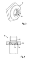
- Fig. 3 shows a driving nut 13, which is part of a test device for the drive device 3.
- a performance test is carried out after the assembly of the drive device.
- the test device by means of the driving nut 13 rotatably coupled to the output shaft 6.
- the driving nut 13 is cone-shaped on the inside and provided with a knurling, which corresponds to the knurling on the connecting portion 12 on the output shaft 6.
- the cone angle of the inner side 14 of the driving nut 13 is adapted to the cone angle of the connecting portion 12 on the output shaft 6.
- a test device 15 is partially shown, by means of which the performance test for the drive device is performed. Before the transmission member 11 ( Fig. 2 ) is placed on the output shaft 6 and connected to this, the test device 15 is first connected to the output shaft 6 by the driving nut 13 is placed on the cone-shaped connecting portion 12. Upon actuation of the drive motor, the output via the output shaft 6 torque can be determined by means of the test device 15.
- an adapter part 16 is used, which has the shape of a conical sleeve, wherein the cone angle of the adapter part 16 is adapted to the cone angle of the connecting portion 12.
- the adapter part 16 is intended to prevent the knurling on both components from being damaged by direct contact between connecting section 12 and driving nut 13.
- the adapter part 16 is made of a softer material than the output shaft 6 and the driving nut 13;
- the adapter part 16 is made in particular of plastic and is designed for example as a disposable part.
- the outer circumferential surface, which faces the inner side 14 of the driving nut 13 in the inserted state and the inner circumferential surface of the adapter part, which faces the connecting portion 12 on the output shaft 6 in the inserted state, are each made smooth-walled.
- the adapter part 16 and the driving nut 13 are pressed axially on the conical seat, whereby at the same time a radial force is exerted, which causes the knurling on the driving nut 13 in the outside of the adapter part and from the inside the knurling of the connecting portion 12 in the inside of the adapter part is pressed. Since the adapter part is made of a softer material, the risk of damage to the knurled surfaces is significantly reduced.
- the driving nut 13 can be axially removed from the output shaft 6, as well as the adapter part 16. Subsequently, the transmission member 11 can be rotatably connected via the connecting portion 12 with the output shaft 6.
Landscapes
- Engineering & Computer Science (AREA)
- Mechanical Engineering (AREA)
- Testing Of Devices, Machine Parts, Or Other Structures Thereof (AREA)
- Connection Of Motors, Electrical Generators, Mechanical Devices, And The Like (AREA)
Applications Claiming Priority (1)
| Application Number | Priority Date | Filing Date | Title |
|---|---|---|---|
| DE201010044096 DE102010044096A1 (de) | 2010-11-18 | 2010-11-18 | Prüfeinrichtung für eine Antriebseinrichtung einer Scheibenwischvorrichtung |
Publications (1)
| Publication Number | Publication Date |
|---|---|
| EP2455264A2 true EP2455264A2 (fr) | 2012-05-23 |
Family
ID=44883094
Family Applications (1)
| Application Number | Title | Priority Date | Filing Date |
|---|---|---|---|
| EP11182604A Withdrawn EP2455264A2 (fr) | 2010-11-18 | 2011-09-23 | Dispositif de contrôle pour un dispositif d'entraînement d'un dispositif d'essuie-glace |
Country Status (2)
| Country | Link |
|---|---|
| EP (1) | EP2455264A2 (fr) |
| DE (1) | DE102010044096A1 (fr) |
Cited By (2)
| Publication number | Priority date | Publication date | Assignee | Title |
|---|---|---|---|---|
| FR3063315A1 (fr) * | 2017-02-27 | 2018-08-31 | Valeo Systemes D'essuyage | Carter d'un groupe motoreducteur associe a un arbre de sortie apte a mouvoir un systeme d'essuyage pour une surface vitree d'un vehicule automobile |
| EP3798069A1 (fr) * | 2019-09-24 | 2021-03-31 | Robert Bosch GmbH | Dispositif essuie-glace ainsi que procédé de fabrication d'un dispositif essuie-glace |
-
2010
- 2010-11-18 DE DE201010044096 patent/DE102010044096A1/de not_active Withdrawn
-
2011
- 2011-09-23 EP EP11182604A patent/EP2455264A2/fr not_active Withdrawn
Non-Patent Citations (1)
| Title |
|---|
| None |
Cited By (2)
| Publication number | Priority date | Publication date | Assignee | Title |
|---|---|---|---|---|
| FR3063315A1 (fr) * | 2017-02-27 | 2018-08-31 | Valeo Systemes D'essuyage | Carter d'un groupe motoreducteur associe a un arbre de sortie apte a mouvoir un systeme d'essuyage pour une surface vitree d'un vehicule automobile |
| EP3798069A1 (fr) * | 2019-09-24 | 2021-03-31 | Robert Bosch GmbH | Dispositif essuie-glace ainsi que procédé de fabrication d'un dispositif essuie-glace |
Also Published As
| Publication number | Publication date |
|---|---|
| DE102010044096A1 (de) | 2012-05-24 |
Similar Documents
| Publication | Publication Date | Title |
|---|---|---|
| EP2496852B1 (fr) | Douille pour une unité d'entraînement et unité d'entraînement | |
| DE102004016810A1 (de) | Scheibenwischvorrichtung, insbesondere für ein Kraftfahrzeug | |
| EP1875090B9 (fr) | Procede pour loger un arbre et disposition de palier | |
| DE102008028768A1 (de) | Zahnstange für eine Zahnstangenlenkung | |
| DE102007046527A1 (de) | Lagereinheit | |
| DE102018110485A1 (de) | Antriebseinheit mit einer Elektromaschine und einem Getriebe | |
| EP2455264A2 (fr) | Dispositif de contrôle pour un dispositif d'entraînement d'un dispositif d'essuie-glace | |
| EP1444118B1 (fr) | Systeme d'essuie-glace, destine en particulier a un vehicule automobile | |
| DE102009027285A1 (de) | Antriebseinheit einer Scheibenwischvorrichtung in einem Fahrzeug | |
| DE10324277B4 (de) | Scheibenwischeranlage | |
| EP1395467B1 (fr) | Dispositif d'essuie-glace, en particulier pour un vehicule automobile | |
| EP3798069B1 (fr) | Dispositif essuie-glace ainsi que procédé de fabrication d'un dispositif essuie-glace | |
| DE102014208800A1 (de) | Kunststoffplanetenrad mit eingespritztem Lager sowie Planetengetriebe | |
| DE102012209023A1 (de) | Gelenkstange in einem Wischergestänge für eine Scheibenwischvorrichtung | |
| DE102010044100B4 (de) | Antriebseinrichtung für eine Scheibenwischvorrichtung in einem Fahrzeug | |
| DE102009055106B4 (de) | Scheibenwischvorrichtung, insbesondere für ein Kraftfahrzeug | |
| DE102008001685A1 (de) | Scheibenwischervorrichtung | |
| WO2008000338A1 (fr) | Commande d'essuie-glace par moteur électrique | |
| DE102015215956A1 (de) | Antriebseinrichtung für eine Scheibenwischvorrichtung | |
| DE102006027773A1 (de) | Fahrzeugbremsanlagen-Kolbenpumpe | |
| DE102009054721B4 (de) | Welle in einem Wellenlager, insbesondere Antriebswelle für eine Scheibenwischvorrichtung | |
| DE102009046793A1 (de) | Scheibenwischvorrichtung für ein Kraftfahrzeug | |
| WO2015124364A1 (fr) | Dispositif d'entraînement pour un ensemble essuie-glace | |
| DE102013203595A1 (de) | Scheibenwischervorrichtung mit verbesserter Lebensdauer | |
| DE102008042950A1 (de) | Scheibenwischerantrieb |
Legal Events
| Date | Code | Title | Description |
|---|---|---|---|
| PUAI | Public reference made under article 153(3) epc to a published international application that has entered the european phase |
Free format text: ORIGINAL CODE: 0009012 |
|
| AK | Designated contracting states |
Kind code of ref document: A2 Designated state(s): AL AT BE BG CH CY CZ DE DK EE ES FI FR GB GR HR HU IE IS IT LI LT LU LV MC MK MT NL NO PL PT RO RS SE SI SK SM TR |
|
| AX | Request for extension of the european patent |
Extension state: BA ME |
|
| STAA | Information on the status of an ep patent application or granted ep patent |
Free format text: STATUS: THE APPLICATION IS DEEMED TO BE WITHDRAWN |
|
| 18D | Application deemed to be withdrawn |
Effective date: 20160401 |