EP2455559A2 - Dichtung - Google Patents
Dichtung Download PDFInfo
- Publication number
- EP2455559A2 EP2455559A2 EP20110009076 EP11009076A EP2455559A2 EP 2455559 A2 EP2455559 A2 EP 2455559A2 EP 20110009076 EP20110009076 EP 20110009076 EP 11009076 A EP11009076 A EP 11009076A EP 2455559 A2 EP2455559 A2 EP 2455559A2
- Authority
- EP
- European Patent Office
- Prior art keywords
- seal
- sealing profile
- sealing
- profile section
- slot
- Prior art date
- Legal status (The legal status is an assumption and is not a legal conclusion. Google has not performed a legal analysis and makes no representation as to the accuracy of the status listed.)
- Granted
Links
- 238000007789 sealing Methods 0.000 claims abstract description 76
- 230000006378 damage Effects 0.000 claims abstract 2
- 238000010276 construction Methods 0.000 claims description 4
- 230000005540 biological transmission Effects 0.000 description 3
- 230000000694 effects Effects 0.000 description 3
- 238000009434 installation Methods 0.000 description 3
- 239000002131 composite material Substances 0.000 description 1
- 230000006866 deterioration Effects 0.000 description 1
- 230000037431 insertion Effects 0.000 description 1
- 238000003780 insertion Methods 0.000 description 1
- 239000002184 metal Substances 0.000 description 1
- 238000003825 pressing Methods 0.000 description 1
- 239000003566 sealing material Substances 0.000 description 1
- 238000000926 separation method Methods 0.000 description 1
Images



Classifications
-
- E—FIXED CONSTRUCTIONS
- E04—BUILDING
- E04B—GENERAL BUILDING CONSTRUCTIONS; WALLS, e.g. PARTITIONS; ROOFS; FLOORS; CEILINGS; INSULATION OR OTHER PROTECTION OF BUILDINGS
- E04B2/00—Walls, e.g. partitions, for buildings; Wall construction with regard to insulation; Connections specially adapted to walls
- E04B2/88—Curtain walls
- E04B2/96—Curtain walls comprising panels attached to the structure through mullions or transoms
- E04B2/967—Details of the cross-section of the mullions or transoms
-
- E—FIXED CONSTRUCTIONS
- E06—DOORS, WINDOWS, SHUTTERS, OR ROLLER BLINDS IN GENERAL; LADDERS
- E06B—FIXED OR MOVABLE CLOSURES FOR OPENINGS IN BUILDINGS, VEHICLES, FENCES OR LIKE ENCLOSURES IN GENERAL, e.g. DOORS, WINDOWS, BLINDS, GATES
- E06B3/00—Window sashes, door leaves, or like elements for closing wall or like openings; Layout of fixed or moving closures, e.g. windows in wall or like openings; Features of rigidly-mounted outer frames relating to the mounting of wing frames
- E06B3/54—Fixing of glass panes or like plates
- E06B3/58—Fixing of glass panes or like plates by means of borders, cleats, or the like
- E06B3/62—Fixing of glass panes or like plates by means of borders, cleats, or the like of rubber-like elastic cleats
-
- E—FIXED CONSTRUCTIONS
- E04—BUILDING
- E04D—ROOF COVERINGS; SKY-LIGHTS; GUTTERS; ROOF-WORKING TOOLS
- E04D3/00—Roof covering by making use of flat or curved slabs or stiff sheets
- E04D3/02—Roof covering by making use of flat or curved slabs or stiff sheets of plane slabs, slates, or sheets, or in which the cross-section is unimportant
- E04D3/06—Roof covering by making use of flat or curved slabs or stiff sheets of plane slabs, slates, or sheets, or in which the cross-section is unimportant of glass or other translucent material; Fixing means therefor
- E04D3/08—Roof covering by making use of flat or curved slabs or stiff sheets of plane slabs, slates, or sheets, or in which the cross-section is unimportant of glass or other translucent material; Fixing means therefor with metal glazing bars
- E04D2003/0818—Roof covering by making use of flat or curved slabs or stiff sheets of plane slabs, slates, or sheets, or in which the cross-section is unimportant of glass or other translucent material; Fixing means therefor with metal glazing bars the supporting section of the glazing bar consisting of several parts, e.g. compound sections
- E04D2003/0825—Roof covering by making use of flat or curved slabs or stiff sheets of plane slabs, slates, or sheets, or in which the cross-section is unimportant of glass or other translucent material; Fixing means therefor with metal glazing bars the supporting section of the glazing bar consisting of several parts, e.g. compound sections the metal section covered by parts of other material
- E04D2003/0831—Glazing gaskets of particular shape
-
- E—FIXED CONSTRUCTIONS
- E04—BUILDING
- E04D—ROOF COVERINGS; SKY-LIGHTS; GUTTERS; ROOF-WORKING TOOLS
- E04D3/00—Roof covering by making use of flat or curved slabs or stiff sheets
- E04D3/02—Roof covering by making use of flat or curved slabs or stiff sheets of plane slabs, slates, or sheets, or in which the cross-section is unimportant
- E04D3/06—Roof covering by making use of flat or curved slabs or stiff sheets of plane slabs, slates, or sheets, or in which the cross-section is unimportant of glass or other translucent material; Fixing means therefor
- E04D3/08—Roof covering by making use of flat or curved slabs or stiff sheets of plane slabs, slates, or sheets, or in which the cross-section is unimportant of glass or other translucent material; Fixing means therefor with metal glazing bars
- E04D2003/0843—Clamping of the sheets or glass panes to the glazing bars by means of covering strips
- E04D2003/0856—Clamping of the sheets or glass panes to the glazing bars by means of covering strips locked by screws, bolts or pins
-
- E—FIXED CONSTRUCTIONS
- E04—BUILDING
- E04D—ROOF COVERINGS; SKY-LIGHTS; GUTTERS; ROOF-WORKING TOOLS
- E04D3/00—Roof covering by making use of flat or curved slabs or stiff sheets
- E04D3/02—Roof covering by making use of flat or curved slabs or stiff sheets of plane slabs, slates, or sheets, or in which the cross-section is unimportant
- E04D3/06—Roof covering by making use of flat or curved slabs or stiff sheets of plane slabs, slates, or sheets, or in which the cross-section is unimportant of glass or other translucent material; Fixing means therefor
- E04D3/08—Roof covering by making use of flat or curved slabs or stiff sheets of plane slabs, slates, or sheets, or in which the cross-section is unimportant of glass or other translucent material; Fixing means therefor with metal glazing bars
- E04D2003/0868—Mutual connections and details of glazing bars
-
- E—FIXED CONSTRUCTIONS
- E06—DOORS, WINDOWS, SHUTTERS, OR ROLLER BLINDS IN GENERAL; LADDERS
- E06B—FIXED OR MOVABLE CLOSURES FOR OPENINGS IN BUILDINGS, VEHICLES, FENCES OR LIKE ENCLOSURES IN GENERAL, e.g. DOORS, WINDOWS, BLINDS, GATES
- E06B3/00—Window sashes, door leaves, or like elements for closing wall or like openings; Layout of fixed or moving closures, e.g. windows in wall or like openings; Features of rigidly-mounted outer frames relating to the mounting of wing frames
- E06B3/54—Fixing of glass panes or like plates
- E06B3/58—Fixing of glass panes or like plates by means of borders, cleats, or the like
- E06B3/62—Fixing of glass panes or like plates by means of borders, cleats, or the like of rubber-like elastic cleats
- E06B2003/6208—Fixing of glass panes or like plates by means of borders, cleats, or the like of rubber-like elastic cleats with adjustable dimensions
- E06B2003/6211—Fixing of glass panes or like plates by means of borders, cleats, or the like of rubber-like elastic cleats with adjustable dimensions with tear away strips
-
- E—FIXED CONSTRUCTIONS
- E06—DOORS, WINDOWS, SHUTTERS, OR ROLLER BLINDS IN GENERAL; LADDERS
- E06B—FIXED OR MOVABLE CLOSURES FOR OPENINGS IN BUILDINGS, VEHICLES, FENCES OR LIKE ENCLOSURES IN GENERAL, e.g. DOORS, WINDOWS, BLINDS, GATES
- E06B3/00—Window sashes, door leaves, or like elements for closing wall or like openings; Layout of fixed or moving closures, e.g. windows in wall or like openings; Features of rigidly-mounted outer frames relating to the mounting of wing frames
- E06B3/54—Fixing of glass panes or like plates
- E06B3/58—Fixing of glass panes or like plates by means of borders, cleats, or the like
- E06B3/62—Fixing of glass panes or like plates by means of borders, cleats, or the like of rubber-like elastic cleats
- E06B2003/6217—Fixing of glass panes or like plates by means of borders, cleats, or the like of rubber-like elastic cleats with specific fixing means
- E06B2003/6223—Fixing of glass panes or like plates by means of borders, cleats, or the like of rubber-like elastic cleats with specific fixing means with protruding parts anchored in grooves
-
- E—FIXED CONSTRUCTIONS
- E06—DOORS, WINDOWS, SHUTTERS, OR ROLLER BLINDS IN GENERAL; LADDERS
- E06B—FIXED OR MOVABLE CLOSURES FOR OPENINGS IN BUILDINGS, VEHICLES, FENCES OR LIKE ENCLOSURES IN GENERAL, e.g. DOORS, WINDOWS, BLINDS, GATES
- E06B3/00—Window sashes, door leaves, or like elements for closing wall or like openings; Layout of fixed or moving closures, e.g. windows in wall or like openings; Features of rigidly-mounted outer frames relating to the mounting of wing frames
- E06B3/54—Fixing of glass panes or like plates
- E06B3/58—Fixing of glass panes or like plates by means of borders, cleats, or the like
- E06B3/62—Fixing of glass panes or like plates by means of borders, cleats, or the like of rubber-like elastic cleats
- E06B2003/6238—Fixing of glass panes or like plates by means of borders, cleats, or the like of rubber-like elastic cleats having extra functions
- E06B2003/6244—Fixing of glass panes or like plates by means of borders, cleats, or the like of rubber-like elastic cleats having extra functions with extra parts sealing against the bottom of the glazing rebate or against the edge of the pane
-
- E—FIXED CONSTRUCTIONS
- E06—DOORS, WINDOWS, SHUTTERS, OR ROLLER BLINDS IN GENERAL; LADDERS
- E06B—FIXED OR MOVABLE CLOSURES FOR OPENINGS IN BUILDINGS, VEHICLES, FENCES OR LIKE ENCLOSURES IN GENERAL, e.g. DOORS, WINDOWS, BLINDS, GATES
- E06B3/00—Window sashes, door leaves, or like elements for closing wall or like openings; Layout of fixed or moving closures, e.g. windows in wall or like openings; Features of rigidly-mounted outer frames relating to the mounting of wing frames
- E06B3/54—Fixing of glass panes or like plates
- E06B3/58—Fixing of glass panes or like plates by means of borders, cleats, or the like
- E06B3/62—Fixing of glass panes or like plates by means of borders, cleats, or the like of rubber-like elastic cleats
- E06B2003/6238—Fixing of glass panes or like plates by means of borders, cleats, or the like of rubber-like elastic cleats having extra functions
- E06B2003/6247—Fixing of glass panes or like plates by means of borders, cleats, or the like of rubber-like elastic cleats having extra functions with extra parts sealing against the fixed or another window frame
-
- E—FIXED CONSTRUCTIONS
- E06—DOORS, WINDOWS, SHUTTERS, OR ROLLER BLINDS IN GENERAL; LADDERS
- E06B—FIXED OR MOVABLE CLOSURES FOR OPENINGS IN BUILDINGS, VEHICLES, FENCES OR LIKE ENCLOSURES IN GENERAL, e.g. DOORS, WINDOWS, BLINDS, GATES
- E06B3/00—Window sashes, door leaves, or like elements for closing wall or like openings; Layout of fixed or moving closures, e.g. windows in wall or like openings; Features of rigidly-mounted outer frames relating to the mounting of wing frames
- E06B3/54—Fixing of glass panes or like plates
- E06B3/58—Fixing of glass panes or like plates by means of borders, cleats, or the like
- E06B3/62—Fixing of glass panes or like plates by means of borders, cleats, or the like of rubber-like elastic cleats
- E06B2003/625—Specific form characteristics
- E06B2003/6255—H-shaped
-
- E—FIXED CONSTRUCTIONS
- E06—DOORS, WINDOWS, SHUTTERS, OR ROLLER BLINDS IN GENERAL; LADDERS
- E06B—FIXED OR MOVABLE CLOSURES FOR OPENINGS IN BUILDINGS, VEHICLES, FENCES OR LIKE ENCLOSURES IN GENERAL, e.g. DOORS, WINDOWS, BLINDS, GATES
- E06B3/00—Window sashes, door leaves, or like elements for closing wall or like openings; Layout of fixed or moving closures, e.g. windows in wall or like openings; Features of rigidly-mounted outer frames relating to the mounting of wing frames
- E06B3/54—Fixing of glass panes or like plates
- E06B3/58—Fixing of glass panes or like plates by means of borders, cleats, or the like
- E06B3/62—Fixing of glass panes or like plates by means of borders, cleats, or the like of rubber-like elastic cleats
- E06B2003/625—Specific form characteristics
- E06B2003/6267—Specific form characteristics consisting of several separate parts
Definitions
- the present innovation relates to a seal, in particular inner seal according to the preamble of claim 1.
- the individual filling elements such as e.g. Glazing or facade panel elements fixed to profiles, wherein between the profile and the filling element, an inner seal is arranged.
- the filling elements are held with the interposition of outer sealing elements by a pressure profile, which is stretched against the profile.
- the object of the present innovation is to provide a generic inner seal for a profile frame construction with improved sealing effect.
- the above object is according to the invention achieved in that the first and second and sealing profile portion of the sealing profile of the seal is separated by at least one substantially line-like slot, wherein the slot preferably has a curved or an angular course.
- the width of the slot is dimensioned such that, when the sealing profile is loaded, the wall sections of the first and second sealing profile sections defining the slot abut each other substantially in a form-fitting manner.
- two slots may be provided which are separated from each other by a, preferably central tear bar d. H. communicate with each other about this. This results in advantages when extruding the seal.
- the slots can end either just before the contact surface of the sealing profile, so that a terminal tear-off area or bonding area remains. Alternatively, the two slots can also open outwardly into the contact surface.
- a single, continuous, in particular C-shaped slot is provided.
- a tear-off web is preferably provided at each end remote from the slot.
- the gasket is a one-piece gasket with two gaskets and a central part therebetween.
- the groove serves as a receiving groove for a supplementary seal to ensure a seal height adjustment.
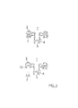
- the seal comprises sealing profile 3 with a first sealing profile section 6, a second sealing profile section 7 and a third sealing profile section 8.
- the third sealing profile section 8 can be connected to the first sealing profile section 6 via a tear-off web 10.
- a C-shaped slot 11c is provided, at the ends of which tear-off webs 9b and 9c are provided in the region of the contact surface of the sealing profile 3.
- the slit 11c causes the wall portion 12a of the first seal profile portion 6 and the wall portion 12b of the second seal profile portion 7 to face each other at a substantially equal distance.
- two obliquely arranged lugs 18, 19 can be provided, which serve to show the fitter the correct installation situation (contact pressure, etc.) by applying pressure optically controllably to the first sealing profile section 6 under contact pressure.
- a further Abreisssteg may be provided or extend the slot to the contact surface. Alternatively, a portion of a light bond may be provided.
- Fig. 2A-G show a sequence of possible variations of the seal according to the invention by means of a one-piece inner seal.
- This comprises a central part 4 with a frontal recess 5, which is intended to receive, for example, a (not shown) sealing part.
- On both sides of the Middle part 4 is the sealing profiles 3 of the type as in Fig. 1B explained.
- a drainage channel 27 is formed between the respective sealing profile 3 and the middle part 4, a drainage channel 27 is formed.
- Fig. 2E can, if necessary, and the second sealing profile portion 7 of the opposite sealing profile 3 are removed, whereby the second receiving groove 13 on the inner seal 1 is free.
- Fig. 2F a second replacement seal 15 are used with the foot 17 in the receiving groove 13 so that again, as in Fig. 2G shown, an increased height of the sealing profile relative to the sealing profile with the first replacement seal 14 can be achieved.
- Fig. 3 is a one-piece inner seal with a sealing profile 3 of the type according to Fig. 1A given again.
- the second sealing profile section 7 can in a corresponding manner by on the separation of the two slot 11 c (see. Fig. 1A ) limiting tear-off webs 9b and 9c are removed and a corresponding replacement seal can be used.
- the variability of in Fig. 3 illustrated seal corresponds to the variability of in Fig. 2A - 2E illustrated seal.
- the Fig. 4A - 4C show various installation situations to illustrate the sealing height adjustment.
- two glazing elements 25 of identical thickness are integrated in a frame composite.
- the respective glazing element 25 between an inner profile 20 and an outer profile 21 by means of a fastening screw 23 which engages in a screw 22 on the inner profile 20, clamped.
- Between the inner profile 20 and the respective glazing element 25 is the one-piece inner seal 1.
- Between the respective glazing element 25 and the outer profile 21, an outer seal 26 is provided in each case.
- On the outside of a cover profile 24 is clipped. Due to the identical height, the inner seal 1 can remain in its basic form, ie on both sides in each case have the second sealing profile section 7. In the clamped state, the second sealing profile section 7 presses on the first sealing profile section 6, as a result of which the slots are reduced in width or completely disappear. Only for graphic reasons, the respective slot in Fig. 4A shown a little wider.
- the resulting offset by the first replacement seal 14 can be compensated in an advantageous manner.
- a further offset as in Fig. 4C is shown. Again, a compensation can be made by a second replacement seal.
- the innovation creates a novel seal, which releases a generous receiving groove 13 after removal of the second sealing profile section 7, leaving essentially only two L-shaped webs, so that space for a sealing foot is created, which minus the two narrow webs over the entire Width of the sealing profile 3 may extend.
- the seal according to the invention therefore allows a very high variability, without sacrificing the sealing function of the base seal.
- the user can stock up on a basic requirement for sealing material.
- Replacement seals can also be used flexibly and at short notice on site as needed to compensate for differences in filling thickness or even tolerances.
- Conventional standard seals can be used in the receiving groove of the inventive seal.
Landscapes
- Engineering & Computer Science (AREA)
- Civil Engineering (AREA)
- Structural Engineering (AREA)
- Architecture (AREA)
- Physics & Mathematics (AREA)
- Electromagnetism (AREA)
- Specific Sealing Or Ventilating Devices For Doors And Windows (AREA)
- Building Environments (AREA)
- Gasket Seals (AREA)
- Processing Of Solid Wastes (AREA)
Abstract
Description
- Die vorliegende Neuerung betrifft eine Dichtung, insbesondere Innendichtung gemäß dem Oberbegriff des Anspruchs 1.
- Bei Profilrahmenkonstruktionen werden die einzelnen Füllelemente wie z.B. Verglasungselemente oder Fassadenplattenelemente an Profilen fixiert, wobei zwischen dem Profil und dem Füllelement eine Innendichtung angeordnet ist. Auf der Außenseite der Profilrahmenkonstruktion werden die Füllelemente unter Zwischenschaltung von Außendichtungselementen durch ein Andruckprofil gehalten, welches gegen das Profil gespannt wird.
- Für den Fall, dass unterschiedlich dicke Füllelemente verwendet werden, muss ein Füllungsdickenausgleich vorgenommen werden. Hierzu werden üblicherweise Innendichtungen verwendet, die im Bereich des Dichtungsprofils eine Ausnehmung für das Einsetzen zusätzlicher Dichtungselemente aufweisen.
- Aus der
DE20 2005 000 604 U1 ist eine Dichtungsanordnung für Fassaden oder Lichtdächer bekannt, bei der eine Nut im Dichtungsprofil der Dichtungsanordnung mittels eines, waagrecht verlaufenden, entfernbaren Steges verschlossen ist. Der Steg wird entfernt, sofern eine Zusatzdichtung zur Erzielung des Fülldickenausgleichs eingesetzt werden soll. Es handelt sich hierbei lediglich um eine Abdeckung der Nut. Hieraus resultiert der Nachteil, dass im Bereich der Abdeckung nur eine reduzierte Dichtwirkung gewährleistet ist. - Die Aufgabe der vorliegenden Neuerung besteht darin eine gattungsgemäße Innendichtung für eine Profilrahmenkonstruktion mit verbesserter Dichtwirkung zur Verfügung zu stellen.
- Die vorstehende Aufgabe wird neuerungsgemäß dadurch gelöst, dass der erste und zweite und Dichtungsprofilabschnitt des Dichtungsprofils der Dichtung durch mindestens einen im Wesentlichen linienartigen Schlitz voneinander getrennt ist, wobei der Schlitz vorzugsweise einen gekrümmten oder einen eckigen Verlauf aufweist. Hierdurch wird, wenn der zweite Dichtungprofilabschnitt am Dichtungsprofil verbleibt, bei Belastung der Dichtung über den gesamten Bereich des Dichtungsprofils also auch im Bereich der Abdeckung der Nut für die Aufnahme einer Zusatzdichtung eine optimale Kraftübertragung und damit eine optimale Dichtwirkung erzielt. Die Randbereiche des Schlitzes bewirken eine großflächige Kraftübertragung. Gleichzeitig kann bei Entfernung des zweiten Dichtungsprofilabschnitts eine großzügige d. h. geräumige Aufnahmekammer für eine Ergänzungsdichtung geschaffen werden, die der Größe einer in einem Metallprofil vorgesehen Dichtungsaufnahmekammer entsprechen kann.
- Zweckmäßige Ausgestaltungen der Neuerung werden in den Unteransprüchen beansprucht und finden sich auch in der Beschreibung des Ausführungsbeispiels. Insbesondere ist die Breite des Schlitzes derart bemessen, dass bei Belastung des Dichtungsprofils sich die den Schlitz festlegenden Wandabschnitte von erstem und zweitem Dichtungsprofilabschnitt im Wesentlichen formgerecht aneinander anliegen.
- Zweckmäßigerweise können zwei Schlitze vorgesehen sein, die von einem, vorzugsweise mittigen Abreisssteg voneinander getrennt sind d. h. über diesen mit einander in Verbindung stehen. Hierduch ergeben sich Vorteile beim Extrudieren der Dichtung.
- Die Schlitze können entweder kurz vor der Kontaktfläche des Dichtungsprofils enden, so dass ein endständiger Absreissbereich oder Verklebungsbereich verbleibt. Alternativ können die beiden Schlitze auch nach außen hin offen in die Kontaktfläche münden.
- Alternativ kann auch ein einziger, durchgängiger insbesondere C-förmiger Schlitz vorgesehen ist. Hierbei ist vorzugsweise je ein Abreisssteg an jedem abgewandten Ende des Schlitzes vorgesehen ist.
- Vorzugsweise handelt es sich bei der Dichtung um eine einteilige Dichtung mit zwei Dichtungsprofilen und einem dazwischen befindlichen Mittelteil.
- Die Nut dient als Aufnahmenut für eine Ergänzungsdichtung zur Gewährleistung einer Dichtungshöhenanpassung.
- Zweckmäßige Ausgestaltungen der vorliegenden Neuerung werden nachstehend anhand von Zeichnungen näher erläutert. Es zeigen:
- Fig. 1
- eine Schnittdarstellung einer ersten (
Fig. 1A ) sowie zweiten Ausgestaltung (Fig. 1B ) der vorliegenden Neuerung, - Fig. 2
- eine Schnittdarstellung einer weiteren Ausgestaltung der Neuerung sowie der Verbindungsmöglichkeiten mit einer oder mehreren Ergänzungsdichtung(en),
- Fig. 3
- eine Schnittdarstellung einer weiteren Ausgestaltung der Neuerung sowie der Verbindungsmöglichkeiten mit einer oder mehreren Ergänzungsdichtung(en) sowie
- Fig.4
- Schnittdarstellungen verschiedener Einbausituationen einer neuerungsgemäßen Dichtung.
- Die Dichtung umfasst Dichtungsprofil 3 mit einem ersten Dichtungsprofilabschnitt 6, einem zweiten Dichtungsprofilabschnitt 7 sowie einem dritten Dichtungsprofilabschnitt 8. Der dritte Dichtungsprofilabschnitt 8 kann mit dem ersten Dichtungsprofilabschnitt 6 über einen Abreisssteg 10 verbunden sein. Zwischen dem ersten Dichtungsprofilabschnitt 6 und dem zweiten Dichtungsprofilabschnitt 7 ist ein C-förmiger Schlitz 11c vorgesehen, an dessen Enden Abreissstege 9b sowie 9c im Bereich der Kontaktfläche des Dichtungsprofils 3 vorgesehen sind. Der Schlitz 11c bewirkt, dass sich der Wandabschnitt 12a des ersten Dichtungsprofilabschnitts 6 und der Wandabschnitt 12b des zweiten Dichtungsprofilabschnitt 7 in einem im Wesentlichen gleichen Abstand gegenüberliegen.
- Wird die Dichtung 1 zusammengedrückt, reduziert sich dieser Abstand und die Wandabschnitte 12a sowie 12b liegen dann im Wesentlichen unmittelbar aneinander. Hierdurch wird eine optimale Kraftübertragung erreicht, so dass die Dichtung trotz der Variabilität durch die Entnahmemöglichkeit des zweiten Dichtungsprofilabschnitts 7 keine Funktionsverschlechterung erleidet
- Im Bereich des zweiten Dichtungsprofilabschnitts 7 können zwei schräg angeordnete Fahnen 18, 19 vorgesehen sein, die dazu dienen, dem Monteur die korrekte Einbausituation (Anpressdruck etc.) anzuzeigen, indem sie sich unter Anpressdruck optisch kontrollierbar an dem ersten Dichtungsprofilabschnitt 6 anlegen.
- Bei der Ausgestaltung nach
Fig. 1B sind anstelle eines Schlitzes zwei getrennte, gekrümmte Schlitze 11a, 11b vorgesehen. Im Mittelbereich befindet sich ein Abreisssteg 9a, der die Enden der beiden Schlitze 11a, 11b mit einander verbindet. Am äußeren Ende des jeweiligen Schlitzes 11a bzw. 11b kann ein weiterer Abreisssteg vorgesehen sein oder aber der Schlitz bis zur Kontaktfläche sich erstrecken. Alternativ kann ein Abschnitt einer leichten Verklebung vorgesehen sein. -
Fig. 2A-G zeigen eine Abfolge der Variationsmöglichkeiten der erfindungsgemäßen Dichtung anhand einer einteiligen Innendichtung. Diese umfasst einen Mittelteil 4 mit einer stirnseitigen Ausnehmung 5, die dazu vorgesehen ist, beispielsweise ein (nicht dargestelltes) Dichtteil aufzunehmen. Beidseitig zu dem Mittelteil 4 befindet sich die Dichtungsprofile 3 der Art wie inFig. 1B erläutert. Zwischen dem jeweiligen Dichtungsprofil 3 und dem Mittelteil 4 wird eine Entwässerungsrinne 27 gebildet. - In der in
Fig. 2A wieder gegebenen Darstellung befinden sich auf beiden Seiten des Mittelteils 4 Dichtungsprofile 3 gleicher Höhe, wobei in jedem Dichtungsprofil 3 der zweite Dichtungsprofilabschnitt 7 vorhanden ist. - In den Darstellungen gemäß
Fig. 2B und C wird einer der beiden zweiten Dichtungsprofilabschnitte 7 entfernt, so dass dort die Aufnahmenut 13 freigegeben wird und eine erste Ersatzdichtung 14 in die Aufnahmenut 13 mit deren Fuß 15 eingesetzt wird, so dass die Höhe des dortigen Dichtungsprofils 3 vergrößert wird, wie dies ausFig. 2D ersichtlich ist. - Gemäß
Fig. 2E kann, bei Bedarf, auch der zweite Dichtungsprofilabschnitt 7 des gegenüberliegenden Dichtungsprofils 3 entfernt werden, wodurch der zweiten Aufnahmenut 13 an der Innendichtung 1 frei wird. In diese Aufnahmenut kann, wie ausFig. 2F ersichtlich, eine zweite Ersatzdichtung 15 mit deren Fuß 17 in die Aufnahmenut 13 eingesetzt werden, so dass wieder, wie inFig. 2G dargestellt, eine vergrößerte Höhe des Dichtungsprofils gegenüber dem Dichtungsprofil mit der ersten Ersatzdichtung 14 erzielt werden kann. - Die Darstellung gemäß
Fig. 2A - 2G zeigen die Variationsbreite der neuerungsgemäßen Dichtung. - In
Fig. 3 ist eine einteilige Innendichtung mit einem Dichtungsprofil 3 der Art gemäßFig. 1A wieder gegeben. - Der zweite Dichtungsprofilabschnitt 7 kann in entsprechender Weise durch Auf trennen der beiden den Schlitz 11c (vergl.
Fig. 1A ) begrenzenden Abreißstege 9b sowie 9c entfernt werden und eine entsprechende Ersatzdichtung eingesetzt werden. Die Variabilität der inFig. 3 dargestellten Dichtung entspricht der Variabilität der inFig. 2A - 2E dargestellten Dichtung. - Die
Fig. 4A - 4C zeigen verschiedene Einbausituationen zur Verdeutlichung der Dichtungshöhenanpassung. - In der Ausgestaltung nach
Fig. 4A sind zwei Verglasungselemente 25 von identischer Stärke in einem Rahmenverbund eingebunden. Hierbei wird das jeweilige Verglasungselement 25 zwischen einem Innenprofil 20 und einem Außenprofil 21 mittels einer Befestigungsschraube 23, die in einen Schraubkanal 22 am Innenprofil 20 eingreift, verspannt. Zwischen dem Innenprofil 20 und dem jeweiligen Verglasungselement 25 befindet sich die einteilige Innendichtung 1. Zwischen dem jeweiligen Verglasungselement 25 und dem Außenprofil 21 ist jeweils eine Außendichtung 26 vorgesehen. An der Außenseite wird eine Deckprofil 24 aufgeklipst. Aufgrund der identischen Höhe kann die Innendichtung 1 in ihrer Grundform verbleiben, d.h. beidseitig jeweils den zweiten Dichtungsprofilabschnitt 7 aufweisen. In dem verspannten Zustand drückt der zweite Dichtungsprofilabschnitt 7 auf den ersten Dichtungsprofilabschnitt 6, wodurch sich die Schlitze in ihrer Breite reduzieren oder vollständig verschwinden. Lediglich aus zeichnerischen Gründen ist der jeweilige Schlitz inFig. 4A etwas breiter dargestellt. - Sofern, wie in
Fig. 4B gezeigt Verglasungselemente 25, 25a unterschiedliche Stärke verwendet werden, kann der hierdurch entstehende Versatz durch die erste Ersatzdichtung 14 in vorteilhafter Weise ausgeglichen werden. Gleiches gilt für einen weiteren Versatz, wie er inFig. 4C dargestellt ist. Auch hier kann ein Ausgleich durch eine zweite Ersatzdichtung vorgenommen werden. - Die Neuerung schafft eine neuartige Dichtung, die nach Entfernen des zweiten Dichtungsprofilabschnitts 7 eine großzügige Aufnahmenut 13 freigibt, wobei im wesentlichen nur zwei L-förmige Stege verbleiben, so dass Platz für einen Dichtungsfuß geschaffen wird, der sich abzüglich der beiden schmalen Stege über die gesamte Breite des Dichtungsprofils 3 erstrecken kann.
- Die neuerungsgemäße Dichtung ermöglicht daher eine sehr hohe Variabilität, ohne Einbußen der Dichtfunktion der Grunddichtung. Der Anwender kann sich mit einem Grundbedarf an Dichtungsmaterial eindecken. Ersatzdichtungen können flexibel und kurzfristig nach Bedarf auch an der Baustelle eingesetzt werden, um Füllungsdickenunterschiede oder auch Toleranzen auszugleichen. Herkömmliche Standarddichtungen können in die Aufnahmenut der neuerungsgemäßen Dichtung eingesetzt werden.
-
- 1
- Innendichtung
- 2
- Dichtungsfuß
- 3
- Dichtungsprofil
- 4
- Mittelteil
- 5
- Ausnehmung
- 6
- erster Dichtungsprofilabschnitt
- 7
- zweiter Dichtungsprofilabschnitt
- 8
- dritter Dichtungsprofilabschnitt
- 9
- Abreisssteg
- 10
- Abreisssteg
- 11
- Schlitz
- 12
- Wandabschnitt
- 13
- Aufnahmenut
- 14
- erste Ersatzdichtung
- 15
- Fuß erste Ersatzdichtung
- 16
- zweite Ersatzdichtung
- 17
- Fuß zweite Ersatzdichtung
- 18
- Fahne
- 19
- Fahne
- 20
- Innenprofil
- 21
- Außenprofil
- 22
- Schraubkanal
- 23
- Befestigungsschraube
- 24
- Deckprofil
- 25
- Verglasungselement
- 26
- Außendichtung
- 27
- Entwässerungsrinne
Claims (8)
- Dichtung, insbesondere Innendichtung für eine Profilrahmenkonstruktion, miteinem Dichtungsfuß (2),einem Dichtungsprofil (3) umfassendeinen erster Dichtungsprofilabschnitt (6),einen zweiten Dichtungsprofilabschnitt (7) sowiemindestens einem Abreisssteg (9) zwischen erstem und zweitem Dichtungsprofilabschnitt (6 bzw. 7), wobeidurch Zerstörung des Abreisssteges (9) der zweite Dichtungsprofilabschnitt (7) entfernbar ist und hierdurch eine durch den ersten Dichtungsprofilabschnitt (6) festgelegte Nut (13) von außen zugänglich ist,dadurch gekennzeichnet, dass
erster und zweiter Dichtungsprofilabschnitt (6 bzw. 7) durch mindestens eckigen oder gekrümmten Schlitz (11) voneinander getrennt sind - Dichtung nach Anspruch 1,
dadurch gekennzeichnet, dass
die Breite des Schlitzes (11) derart bemessen ist, dass bei Belastung des Dichtungsprofils (3) sich die den Schlitz (11) festlegenden Wandabschnitte (12a, 12b) von erstem und zweitem Dichtungsprofilabschnitt (6, bzw. 7) im wesentlichen formgerecht aneinander anliegen. - Dichtung nach Anspruch 1 oder 2,
dadurch gekennzeichnet, dass
zwei Schlitze (11a, 11b) vorgesehen sind, die von einem Abreisssteg (9a) voneinander getrennt sind. - Dichtung nach Anspruch 1 oder 2,
dadurch gekennzeichnet, dass
ein einziger, durchgängiger insbesondere C-förmiger Schlitz (11c) vorgesehen ist. - Dichtung nach mindestens einem der vorhergehenden Ansprüche,
dadurch gekennzeichnet, dass
zwei Abreissstege (9b, 9c) gegenüberliegend am zweiten Dichtungsprofilabschnitt (7) vorgesehen sind. - Dichtung nach mindestens einem der vorhergehenden Ansprüche,
dadurch gekennzeichnet, dass
es sich um eine einteilige Dichtung mit zwei Dichtungsprofilen (3) und einem dazwischen befindlichen Mittelteil (4) handelt. - Dichtung nach mindestens einem der vorhergehenden Ansprüche,
dadurch gekennzeichnet, dass
die Nut (13) als Aufnahmenut für eine Ergänzungsdichtung (14, 16) für eine Dichtungshöhenanpassung dient. - Dichtung nach mindestens einem der Ansprüche 5 bis 7,
dadurch gekennzeichnet, dass
der jeweilige Abreisssteg (9b, 9c) einen Vorsprung für den Halt eines Fußes der Ergänzungsdichtung (14, 16) bildet.
Applications Claiming Priority (1)
| Application Number | Priority Date | Filing Date | Title |
|---|---|---|---|
| DE202010015534U DE202010015534U1 (de) | 2010-11-18 | 2010-11-18 | Dichtung |
Publications (3)
| Publication Number | Publication Date |
|---|---|
| EP2455559A2 true EP2455559A2 (de) | 2012-05-23 |
| EP2455559A3 EP2455559A3 (de) | 2014-06-25 |
| EP2455559B1 EP2455559B1 (de) | 2015-09-23 |
Family
ID=45092096
Family Applications (1)
| Application Number | Title | Priority Date | Filing Date |
|---|---|---|---|
| EP11009076.8A Active EP2455559B1 (de) | 2010-11-18 | 2011-11-15 | Dichtung |
Country Status (2)
| Country | Link |
|---|---|
| EP (1) | EP2455559B1 (de) |
| DE (1) | DE202010015534U1 (de) |
Families Citing this family (2)
| Publication number | Priority date | Publication date | Assignee | Title |
|---|---|---|---|---|
| FR3072984B1 (fr) * | 2017-11-02 | 2021-10-22 | Sapa As | Joint d’etancheite pour facade rideau, facade rideau comportant de tels joints d’etancheite |
| DE102022101202A1 (de) | 2022-01-19 | 2023-07-20 | Heroal - Johann Henkenjohann Gmbh & Co. Kg | Dichtleiste für einen aus einzelnen Rahmenprofilen zusammengesetzten Rahmen eines Fensters, einer Tür oder einer Fassade |
Citations (1)
| Publication number | Priority date | Publication date | Assignee | Title |
|---|---|---|---|---|
| DE202005000604U1 (de) | 2005-01-14 | 2006-05-24 | SCHÜCO International KG | Dichtungsanordnung für Fassaden oder Lichtdächer |
Family Cites Families (3)
| Publication number | Priority date | Publication date | Assignee | Title |
|---|---|---|---|---|
| DE20021279U1 (de) * | 2000-12-15 | 2001-03-22 | Schüco International KG, 33609 Bielefeld | Fassade und/oder Dach und Glasauflagedichtung |
| DE20219276U1 (de) * | 2002-12-12 | 2003-03-13 | Evg Bauprofil System Entwicklungs- Und Vermarktungsgesellschaft Mbh, Eugendorf | Innendichtung mit Füllungsdickenausgleich |
| DE202006011255U1 (de) * | 2006-07-19 | 2006-11-23 | Raico Bautechnik Gmbh | Auflagedichtung |
-
2010
- 2010-11-18 DE DE202010015534U patent/DE202010015534U1/de not_active Expired - Lifetime
-
2011
- 2011-11-15 EP EP11009076.8A patent/EP2455559B1/de active Active
Patent Citations (1)
| Publication number | Priority date | Publication date | Assignee | Title |
|---|---|---|---|---|
| DE202005000604U1 (de) | 2005-01-14 | 2006-05-24 | SCHÜCO International KG | Dichtungsanordnung für Fassaden oder Lichtdächer |
Also Published As
| Publication number | Publication date |
|---|---|
| EP2455559A3 (de) | 2014-06-25 |
| DE202010015534U1 (de) | 2012-03-01 |
| EP2455559B1 (de) | 2015-09-23 |
Similar Documents
| Publication | Publication Date | Title |
|---|---|---|
| EP2813783A1 (de) | Ständer zum Abstützen von Solarpaneelen auf einem Flachdach | |
| DE102017212009A1 (de) | Zugentlastungstülle | |
| DE20100747U1 (de) | Riegel/Pfosten-Konstruktion | |
| DE202012104033U1 (de) | Haltevorrichtung für eine Brüstungs- oder Geländerplatte sowie Geländer oder Brüstung mit Scheibe | |
| EP2792834B1 (de) | Anordnung umfassend ein Halteprofil für ein Rahmenprofil sowie rahmenintegrierte Absturzsicherung | |
| EP1881147B1 (de) | Auflagedichtung zwischen einem Füllelement und einem Rahmenprofil | |
| EP2455559B1 (de) | Dichtung | |
| EP3667009A1 (de) | Fenster und verfahren zur montage eines fensters | |
| EP1643049B1 (de) | Tragprofilkonstruktion | |
| EP2754803B1 (de) | Riegelstangenbeschlag für ein Fenster oder eine Tür und Riegelstange für einen solchen Riegelstangenbeschlag | |
| EP1840314B1 (de) | Bauelement in Brandschutzausführung | |
| AT516721B1 (de) | Geländer und Verfahren zur Herstellung eines Geländers | |
| EP1327035B1 (de) | Trägereinheit im Glasfalz einer Fassade oder eines Lichtdaches | |
| EP3719243B1 (de) | T-verbinder, insbesondere sprossenverbinder, für geklebte verglasungen | |
| DE102011008765A1 (de) | Profilanordnung, Rahmen und Rahmenanordnung | |
| DE102005001263B4 (de) | Lasche zur Verbindung von Fenster- oder Türrahmen an einem Stockrahmen oder an einer Wandbegrenzung | |
| EP0623730B1 (de) | Elastische Strangdichtung für Fenster, Türen oder dgl. | |
| DE10034889B4 (de) | Spreizglashalter | |
| EP2372038B1 (de) | Fassadenkonstruktion | |
| EP2607554B1 (de) | Wandelement für eine Lärmschutzwand | |
| DE102008012551B4 (de) | Fensteranordnung für ein Schienenfahrzeug | |
| EP1857605B1 (de) | Bodenabdeckung für ein Gebäudeteil | |
| DE3744223C1 (en) | Bulletproof frame leg | |
| EP4174242A1 (de) | Dichtungsanordnung zur abdichtung des übergangs zwischen fassadenelementen einer elementfassade | |
| DE102013003718B4 (de) | Leichtmetall-Gehäuse aus Eckprofilen und Wandelementen |
Legal Events
| Date | Code | Title | Description |
|---|---|---|---|
| PUAI | Public reference made under article 153(3) epc to a published international application that has entered the european phase |
Free format text: ORIGINAL CODE: 0009012 |
|
| AK | Designated contracting states |
Kind code of ref document: A2 Designated state(s): AL AT BE BG CH CY CZ DE DK EE ES FI FR GB GR HR HU IE IS IT LI LT LU LV MC MK MT NL NO PL PT RO RS SE SI SK SM TR |
|
| AX | Request for extension of the european patent |
Extension state: BA ME |
|
| PUAL | Search report despatched |
Free format text: ORIGINAL CODE: 0009013 |
|
| AK | Designated contracting states |
Kind code of ref document: A3 Designated state(s): AL AT BE BG CH CY CZ DE DK EE ES FI FR GB GR HR HU IE IS IT LI LT LU LV MC MK MT NL NO PL PT RO RS SE SI SK SM TR |
|
| AX | Request for extension of the european patent |
Extension state: BA ME |
|
| RIC1 | Information provided on ipc code assigned before grant |
Ipc: E04D 3/08 20060101ALI20140522BHEP Ipc: E06B 3/62 20060101ALI20140522BHEP Ipc: E04B 2/96 20060101AFI20140522BHEP |
|
| 17P | Request for examination filed |
Effective date: 20141029 |
|
| RBV | Designated contracting states (corrected) |
Designated state(s): AL AT BE BG CH CY CZ DE DK EE ES FI FR GB GR HR HU IE IS IT LI LT LU LV MC MK MT NL NO PL PT RO RS SE SI SK SM TR |
|
| GRAP | Despatch of communication of intention to grant a patent |
Free format text: ORIGINAL CODE: EPIDOSNIGR1 |
|
| INTG | Intention to grant announced |
Effective date: 20150417 |
|
| GRAS | Grant fee paid |
Free format text: ORIGINAL CODE: EPIDOSNIGR3 |
|
| GRAA | (expected) grant |
Free format text: ORIGINAL CODE: 0009210 |
|
| AK | Designated contracting states |
Kind code of ref document: B1 Designated state(s): AL AT BE BG CH CY CZ DE DK EE ES FI FR GB GR HR HU IE IS IT LI LT LU LV MC MK MT NL NO PL PT RO RS SE SI SK SM TR |
|
| REG | Reference to a national code |
Ref country code: GB Ref legal event code: FG4D Free format text: NOT ENGLISH |
|
| REG | Reference to a national code |
Ref country code: CH Ref legal event code: EP |
|
| REG | Reference to a national code |
Ref country code: AT Ref legal event code: REF Ref document number: 751343 Country of ref document: AT Kind code of ref document: T Effective date: 20151015 |
|
| REG | Reference to a national code |
Ref country code: IE Ref legal event code: FG4D Free format text: LANGUAGE OF EP DOCUMENT: GERMAN |
|
| REG | Reference to a national code |
Ref country code: DE Ref legal event code: R096 Ref document number: 502011007913 Country of ref document: DE |
|
| REG | Reference to a national code |
Ref country code: CH Ref legal event code: NV Representative=s name: PATENTANWAELTE SCHAAD, BALASS, MENZL AND PARTN, CH |
|
| REG | Reference to a national code |
Ref country code: NL Ref legal event code: MP Effective date: 20150923 |
|
| PG25 | Lapsed in a contracting state [announced via postgrant information from national office to epo] |
Ref country code: FI Free format text: LAPSE BECAUSE OF FAILURE TO SUBMIT A TRANSLATION OF THE DESCRIPTION OR TO PAY THE FEE WITHIN THE PRESCRIBED TIME-LIMIT Effective date: 20150923 Ref country code: LT Free format text: LAPSE BECAUSE OF FAILURE TO SUBMIT A TRANSLATION OF THE DESCRIPTION OR TO PAY THE FEE WITHIN THE PRESCRIBED TIME-LIMIT Effective date: 20150923 Ref country code: LV Free format text: LAPSE BECAUSE OF FAILURE TO SUBMIT A TRANSLATION OF THE DESCRIPTION OR TO PAY THE FEE WITHIN THE PRESCRIBED TIME-LIMIT Effective date: 20150923 Ref country code: NO Free format text: LAPSE BECAUSE OF FAILURE TO SUBMIT A TRANSLATION OF THE DESCRIPTION OR TO PAY THE FEE WITHIN THE PRESCRIBED TIME-LIMIT Effective date: 20151223 Ref country code: GR Free format text: LAPSE BECAUSE OF FAILURE TO SUBMIT A TRANSLATION OF THE DESCRIPTION OR TO PAY THE FEE WITHIN THE PRESCRIBED TIME-LIMIT Effective date: 20151224 |
|
| REG | Reference to a national code |
Ref country code: LT Ref legal event code: MG4D |
|
| PG25 | Lapsed in a contracting state [announced via postgrant information from national office to epo] |
Ref country code: RS Free format text: LAPSE BECAUSE OF FAILURE TO SUBMIT A TRANSLATION OF THE DESCRIPTION OR TO PAY THE FEE WITHIN THE PRESCRIBED TIME-LIMIT Effective date: 20150923 Ref country code: SE Free format text: LAPSE BECAUSE OF FAILURE TO SUBMIT A TRANSLATION OF THE DESCRIPTION OR TO PAY THE FEE WITHIN THE PRESCRIBED TIME-LIMIT Effective date: 20150923 Ref country code: HR Free format text: LAPSE BECAUSE OF FAILURE TO SUBMIT A TRANSLATION OF THE DESCRIPTION OR TO PAY THE FEE WITHIN THE PRESCRIBED TIME-LIMIT Effective date: 20150923 |
|
| PG25 | Lapsed in a contracting state [announced via postgrant information from national office to epo] |
Ref country code: NL Free format text: LAPSE BECAUSE OF FAILURE TO SUBMIT A TRANSLATION OF THE DESCRIPTION OR TO PAY THE FEE WITHIN THE PRESCRIBED TIME-LIMIT Effective date: 20150923 |
|
| PG25 | Lapsed in a contracting state [announced via postgrant information from national office to epo] |
Ref country code: IS Free format text: LAPSE BECAUSE OF FAILURE TO SUBMIT A TRANSLATION OF THE DESCRIPTION OR TO PAY THE FEE WITHIN THE PRESCRIBED TIME-LIMIT Effective date: 20160123 Ref country code: ES Free format text: LAPSE BECAUSE OF FAILURE TO SUBMIT A TRANSLATION OF THE DESCRIPTION OR TO PAY THE FEE WITHIN THE PRESCRIBED TIME-LIMIT Effective date: 20150923 Ref country code: CZ Free format text: LAPSE BECAUSE OF FAILURE TO SUBMIT A TRANSLATION OF THE DESCRIPTION OR TO PAY THE FEE WITHIN THE PRESCRIBED TIME-LIMIT Effective date: 20150923 Ref country code: EE Free format text: LAPSE BECAUSE OF FAILURE TO SUBMIT A TRANSLATION OF THE DESCRIPTION OR TO PAY THE FEE WITHIN THE PRESCRIBED TIME-LIMIT Effective date: 20150923 Ref country code: IT Free format text: LAPSE BECAUSE OF FAILURE TO SUBMIT A TRANSLATION OF THE DESCRIPTION OR TO PAY THE FEE WITHIN THE PRESCRIBED TIME-LIMIT Effective date: 20150923 Ref country code: SK Free format text: LAPSE BECAUSE OF FAILURE TO SUBMIT A TRANSLATION OF THE DESCRIPTION OR TO PAY THE FEE WITHIN THE PRESCRIBED TIME-LIMIT Effective date: 20150923 |
|
| PG25 | Lapsed in a contracting state [announced via postgrant information from national office to epo] |
Ref country code: RO Free format text: LAPSE BECAUSE OF FAILURE TO SUBMIT A TRANSLATION OF THE DESCRIPTION OR TO PAY THE FEE WITHIN THE PRESCRIBED TIME-LIMIT Effective date: 20150923 Ref country code: PL Free format text: LAPSE BECAUSE OF FAILURE TO SUBMIT A TRANSLATION OF THE DESCRIPTION OR TO PAY THE FEE WITHIN THE PRESCRIBED TIME-LIMIT Effective date: 20150923 Ref country code: PT Free format text: LAPSE BECAUSE OF FAILURE TO SUBMIT A TRANSLATION OF THE DESCRIPTION OR TO PAY THE FEE WITHIN THE PRESCRIBED TIME-LIMIT Effective date: 20160125 |
|
| REG | Reference to a national code |
Ref country code: DE Ref legal event code: R097 Ref document number: 502011007913 Country of ref document: DE |
|
| PG25 | Lapsed in a contracting state [announced via postgrant information from national office to epo] |
Ref country code: MC Free format text: LAPSE BECAUSE OF FAILURE TO SUBMIT A TRANSLATION OF THE DESCRIPTION OR TO PAY THE FEE WITHIN THE PRESCRIBED TIME-LIMIT Effective date: 20150923 Ref country code: LU Free format text: LAPSE BECAUSE OF FAILURE TO SUBMIT A TRANSLATION OF THE DESCRIPTION OR TO PAY THE FEE WITHIN THE PRESCRIBED TIME-LIMIT Effective date: 20151115 |
|
| PLBE | No opposition filed within time limit |
Free format text: ORIGINAL CODE: 0009261 |
|
| STAA | Information on the status of an ep patent application or granted ep patent |
Free format text: STATUS: NO OPPOSITION FILED WITHIN TIME LIMIT |
|
| GBPC | Gb: european patent ceased through non-payment of renewal fee |
Effective date: 20151223 |
|
| REG | Reference to a national code |
Ref country code: IE Ref legal event code: MM4A |
|
| REG | Reference to a national code |
Ref country code: FR Ref legal event code: ST Effective date: 20160729 |
|
| 26N | No opposition filed |
Effective date: 20160624 |
|
| PG25 | Lapsed in a contracting state [announced via postgrant information from national office to epo] |
Ref country code: DK Free format text: LAPSE BECAUSE OF FAILURE TO SUBMIT A TRANSLATION OF THE DESCRIPTION OR TO PAY THE FEE WITHIN THE PRESCRIBED TIME-LIMIT Effective date: 20150923 |
|
| PG25 | Lapsed in a contracting state [announced via postgrant information from national office to epo] |
Ref country code: IE Free format text: LAPSE BECAUSE OF NON-PAYMENT OF DUE FEES Effective date: 20151115 Ref country code: GB Free format text: LAPSE BECAUSE OF NON-PAYMENT OF DUE FEES Effective date: 20151223 |
|
| PG25 | Lapsed in a contracting state [announced via postgrant information from national office to epo] |
Ref country code: FR Free format text: LAPSE BECAUSE OF NON-PAYMENT OF DUE FEES Effective date: 20151130 Ref country code: SI Free format text: LAPSE BECAUSE OF FAILURE TO SUBMIT A TRANSLATION OF THE DESCRIPTION OR TO PAY THE FEE WITHIN THE PRESCRIBED TIME-LIMIT Effective date: 20150923 |
|
| PG25 | Lapsed in a contracting state [announced via postgrant information from national office to epo] |
Ref country code: SM Free format text: LAPSE BECAUSE OF FAILURE TO SUBMIT A TRANSLATION OF THE DESCRIPTION OR TO PAY THE FEE WITHIN THE PRESCRIBED TIME-LIMIT Effective date: 20150923 Ref country code: HU Free format text: LAPSE BECAUSE OF FAILURE TO SUBMIT A TRANSLATION OF THE DESCRIPTION OR TO PAY THE FEE WITHIN THE PRESCRIBED TIME-LIMIT; INVALID AB INITIO Effective date: 20111115 Ref country code: BG Free format text: LAPSE BECAUSE OF FAILURE TO SUBMIT A TRANSLATION OF THE DESCRIPTION OR TO PAY THE FEE WITHIN THE PRESCRIBED TIME-LIMIT Effective date: 20150923 |
|
| PG25 | Lapsed in a contracting state [announced via postgrant information from national office to epo] |
Ref country code: CY Free format text: LAPSE BECAUSE OF FAILURE TO SUBMIT A TRANSLATION OF THE DESCRIPTION OR TO PAY THE FEE WITHIN THE PRESCRIBED TIME-LIMIT Effective date: 20150923 |
|
| PG25 | Lapsed in a contracting state [announced via postgrant information from national office to epo] |
Ref country code: BE Free format text: LAPSE BECAUSE OF NON-PAYMENT OF DUE FEES Effective date: 20151130 |
|
| PG25 | Lapsed in a contracting state [announced via postgrant information from national office to epo] |
Ref country code: MT Free format text: LAPSE BECAUSE OF FAILURE TO SUBMIT A TRANSLATION OF THE DESCRIPTION OR TO PAY THE FEE WITHIN THE PRESCRIBED TIME-LIMIT Effective date: 20150923 Ref country code: TR Free format text: LAPSE BECAUSE OF FAILURE TO SUBMIT A TRANSLATION OF THE DESCRIPTION OR TO PAY THE FEE WITHIN THE PRESCRIBED TIME-LIMIT Effective date: 20150923 |
|
| PG25 | Lapsed in a contracting state [announced via postgrant information from national office to epo] |
Ref country code: MK Free format text: LAPSE BECAUSE OF FAILURE TO SUBMIT A TRANSLATION OF THE DESCRIPTION OR TO PAY THE FEE WITHIN THE PRESCRIBED TIME-LIMIT Effective date: 20150923 |
|
| PG25 | Lapsed in a contracting state [announced via postgrant information from national office to epo] |
Ref country code: AL Free format text: LAPSE BECAUSE OF FAILURE TO SUBMIT A TRANSLATION OF THE DESCRIPTION OR TO PAY THE FEE WITHIN THE PRESCRIBED TIME-LIMIT Effective date: 20150923 |
|
| P01 | Opt-out of the competence of the unified patent court (upc) registered |
Effective date: 20230530 |
|
| PGFP | Annual fee paid to national office [announced via postgrant information from national office to epo] |
Ref country code: DE Payment date: 20240805 Year of fee payment: 14 |
|
| PGFP | Annual fee paid to national office [announced via postgrant information from national office to epo] |
Ref country code: AT Payment date: 20241118 Year of fee payment: 14 |
|
| REG | Reference to a national code |
Ref country code: DE Ref legal event code: R082 Ref document number: 502011007913 Country of ref document: DE Representative=s name: 4IP GLEIMPETRI PATENT- UND RECHTSANWALTSPARTNE, DE |
|
| PGFP | Annual fee paid to national office [announced via postgrant information from national office to epo] |
Ref country code: CH Payment date: 20241201 Year of fee payment: 14 |