EP2455578A1 - Seilsystem mit Parallelführung - Google Patents
Seilsystem mit Parallelführung Download PDFInfo
- Publication number
- EP2455578A1 EP2455578A1 EP12155308A EP12155308A EP2455578A1 EP 2455578 A1 EP2455578 A1 EP 2455578A1 EP 12155308 A EP12155308 A EP 12155308A EP 12155308 A EP12155308 A EP 12155308A EP 2455578 A1 EP2455578 A1 EP 2455578A1
- Authority
- EP
- European Patent Office
- Prior art keywords
- cord
- screening arrangement
- cartridge
- screening
- retainer
- Prior art date
- Legal status (The legal status is an assumption and is not a legal conclusion. Google has not performed a legal analysis and makes no representation as to the accuracy of the status listed.)
- Granted
Links
Images



Classifications
-
- E—FIXED CONSTRUCTIONS
- E06—DOORS, WINDOWS, SHUTTERS, OR ROLLER BLINDS IN GENERAL; LADDERS
- E06B—FIXED OR MOVABLE CLOSURES FOR OPENINGS IN BUILDINGS, VEHICLES, FENCES OR LIKE ENCLOSURES IN GENERAL, e.g. DOORS, WINDOWS, BLINDS, GATES
- E06B9/00—Screening or protective devices for wall or similar openings, with or without operating or securing mechanisms; Closures of similar construction
- E06B9/56—Operating, guiding or securing devices or arrangements for roll-type closures; Spring drums; Tape drums; Counterweighting arrangements therefor
- E06B9/58—Guiding devices
-
- E—FIXED CONSTRUCTIONS
- E06—DOORS, WINDOWS, SHUTTERS, OR ROLLER BLINDS IN GENERAL; LADDERS
- E06B—FIXED OR MOVABLE CLOSURES FOR OPENINGS IN BUILDINGS, VEHICLES, FENCES OR LIKE ENCLOSURES IN GENERAL, e.g. DOORS, WINDOWS, BLINDS, GATES
- E06B9/00—Screening or protective devices for wall or similar openings, with or without operating or securing mechanisms; Closures of similar construction
- E06B9/24—Screens or other constructions affording protection against light, especially against sunshine; Similar screens for privacy or appearance; Slat blinds
- E06B9/26—Lamellar or like blinds, e.g. venetian blinds
- E06B9/28—Lamellar or like blinds, e.g. venetian blinds with horizontal lamellae, e.g. non-liftable
- E06B9/30—Lamellar or like blinds, e.g. venetian blinds with horizontal lamellae, e.g. non-liftable liftable
- E06B9/32—Operating, guiding, or securing devices therefor
- E06B9/322—Details of operating devices, e.g. pulleys, brakes, spring drums, drives
-
- E—FIXED CONSTRUCTIONS
- E06—DOORS, WINDOWS, SHUTTERS, OR ROLLER BLINDS IN GENERAL; LADDERS
- E06B—FIXED OR MOVABLE CLOSURES FOR OPENINGS IN BUILDINGS, VEHICLES, FENCES OR LIKE ENCLOSURES IN GENERAL, e.g. DOORS, WINDOWS, BLINDS, GATES
- E06B9/00—Screening or protective devices for wall or similar openings, with or without operating or securing mechanisms; Closures of similar construction
- E06B9/56—Operating, guiding or securing devices or arrangements for roll-type closures; Spring drums; Tape drums; Counterweighting arrangements therefor
- E06B9/58—Guiding devices
- E06B2009/583—Cords or cables
Definitions
- the present invention relates to a parallel guidance cord system comprising a set of cords, each cord having two ends, said screening arrangement having a supply condition and a condition of use.
- the purpose of the cord system is to ensure parallelism between the top element and the bottom element when the screening element is placed in different positions in the frame to be screened. To the extent possible the system also ensures parallel guidance during operation.
- the assembly of the screening arrangement to obtain a supply condition and the subsequent mounting to obtain the condition of use may demand considerable resources. This is, i.a., due to the fact that the cords during the assembly step have to be guided along, threaded through and fastened to different parts of the screening arrangement, all of these operations being relatively cumbersome and labour-intensive. Furthermore, during the mounting step, the cords have to be connected at diametrically opposite corners of the frame opening. This may be performed by connecting the cords to the top element during assembly of the screening arrangement, the opposite ends of the cords being then connected to the opposite frame corner by means of brackets during mounting to attain the condition of use. Alternatively, the cords are provided separately or connected to the bottom element only, in which case also the cord ends near the top element are connected to the frame pieces as well, for instance by means of brackets, or to the top element itself during the mounting procedure.
- a screening arrangement of the kind mentioned in the introduction which is furthermore characterized in that the screening arrangement is provided with a set of cartridges, each cartridge comprising means for engagement with one end of a respective cord, and that each cartridge of said set of cartridges is adapted for sliding engagement with a track inside the top element, said set of cartridges being accommodated inside the top element in the supply condition.
- the assembly is facilitated to a considerable extent, as the cord may very easily be connected to the cartridge outside the top element during assembly of the screening arrangement, following which the cartridge and the cord engaged therewith is slid into the track inside the top element. In this manner, the cord end is safely retained within the top element in the supply condition, without any risk of a consumer interfering with the cord ends, or of the cords being misplaced or not correctly mounted.
- the cartridges may be accommodated in the top element in a permanent manner.
- the sliding engagement between each cartridge and said track is releasable. This makes it possible to withdraw the cartridges from the top element, for instance for maintenance or exchange purposes.
- each cartridge is formed with a shoulder portion for abutment against a corresponding portion or part of the top element.
- the screening arrangement comprises a set of separate springs, and each cartridge is provided with means for holding a spring.
- the provision of the separate springs provides for an easy and flexible assembly of the screening arrangement.
- the parallel guidance system may be made to custom, in accordance with the particularities and the intended field of use of the screening arrangement. For instance, some kinds of screening arrangements may necessitate the use of stiffer springs.
- each spring is a tension spring having a first end and a second end, said means for engagement with one end of said cord being provided by the first end of the spring.
- the holding means for holding the spring on the cartridge preferably comprise a stub portion for holding the second end of said spring and at least one guidance portion for guiding the spring between the first and second ends.
- the cartridge may, in principle, have any suitable dimensions, as long as it may be slid into the track inside the top element.
- the length of the cartridge exceeds the length of the spring in its extended condition.
- the cartridge preferably has an opening for the passage of the cord, said opening having a mouth of smaller dimensions than those of the cord.
- a parallel guidance cord system comprising a set of cords, each cord having two ends.
- the parallel guidance cord system is characterized in that each cord is provided with a first cord end retainer adapted to engage with engagement means of a cartridge of a set of cartridges.
- the first cord end retainer may be formed integrally with said cord, preferably by moulding. This provides for a simple fastening requiring no assembly between the cord and the retainer following the initial step of integrally forming the retainer on the cord.
- the first cord end retainer is connected mechanically to the cord.
- the engagement means may in principle be formed in any suitable manner, as long as a quick and reliable connection between the cord and the cartridge is established.
- the first cord end retainer comprises a hook portion for engagement with the first end of a spring of each cartridge.
- the assembly is particularly simple in an embodiment, in which the first cord end retainer comprises an introduction portion protruding beyond said hook portion.
- the first cord end retainer may comprise a grip portion, which facilitates the assembly even further.
- the grip portion further includes a plurality of flanges interlinked by squeeze portions, said squeeze portions having preferably smaller thickness than the dimension of the cord.
- the second cord end retainer may have any suitable design but is preferably substantially T-shaped.
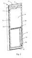
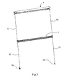
- Figs 1 and 2 show an embodiment of a screening arrangement generally designated 1.
- the screening arrangement is adapted to be mounted on a frame constituted by a sash 2 representing a window.
- the sash 2 is adapted to be connected with a stationary frame (not shown), which in a mounted position of the window lines an opening in a building.
- frame is to be understood as incorporating any substantially rectangular structure positioned in any opening in a building, whether in a wall or the roof, and surrounding an aperture to be screened.
- a screening arrangement according to the invention may just as well be mounted on the stationary frame instead of the sash and may also be utilized in connection with e.g. windows having a frame only, or in doors.
- the screening arrangement 1 comprises a top element 4 adapted to be positioned at the sash top piece 21, a screening body 6 and a bottom element 7. At its upper end edge, the screening body 6 is accommodated in the top element 4 and its opposed, lower end edge is fastened to the bottom element 7.
- the bottom element 7 is adapted to act as a handle during operation of the screening arrangement 1, i.e. when moving the bottom element 7 and hence the screening body 6 between the non-screening position and a screening position, in which the screening body 6 covers the sash aperture partly or fully.
- the screening arrangement may be operated by other means, e.g. by electrical operating means.
- the top element 4 has a left-hand end piece 410 and a right-hand end piece (not shown).
- the terms “left-hand” and “right-hand” refer to the orientation shown in for instance Figs 1 and 2 and are utilized for reasons of convenience only.
- the terms “front” and “back” are utilized to denote the sides of the screening arrangement, "front” being the side intended to face inwards into the room of the building, and “back” the outwards facing side.
- a number of further functions may be built into the end pieces, however, they will not be described in further detail in the present application.
- One of the most important of these functions is that the end piece 410 comprises portions constituting coupling means for cooperation with bracket members positioned on the side piece 23 of the window sash 2.
- the top element 4 comprises a cover 430 extending almost throughout the entire length of the top element 4 from the left-hand end piece 410 to the right-hand end piece, the end pieces thus constituting the end faces of the top element 4.
- the cover 430 is connected to a top rail 440.
- the connection between the top rail 440 and the remaining portion of the top element, i.e. the cover 430 is made integral, e.g. by extruding the top element as a profile including the cover 430 as well as the top rail 440.
- the end piece 410 is fastened to the cover 430 by means of e.g. a screw.
- the top rail 440 has a slightly longer extension in the longitudinal direction than the cover portion 430.
- the top element 4 accommodates a guide bar and a roller bar (not visible).
- the screening body 6 is fastened to the roller bar along its upper end edge in any suitable manner known per se.
- the guide bar guides the screening body 6 onto the roller bar, which serves to collect and store the screening body 6 in the non-screening and partially screened positions of the screening arrangement, or even in the fully screened position, in case the screening body contains surplus material.
- the screening body is wound in mutually opposite directions on the roller bar and the guide bar.
- the side of the screening body 6 facing inwards in the screening positions i.e. the front side facing towards the room in the position of use of the screening arrangement, faces inwards when stored on the roller bar and, hence, the back side faces outwards on the roller bar.
- the bottom element 7 has a general U-shape, the legs of the U extending integrally into the top and bottom edges 71 and 72, respectively, a finger grip 73 being provided by said U-shape.
- a non-screening position in which the U-shape is situated immediately below the guide bar and immediately in front of the front portion of the screening body 6 stored on the roller bar.
- a slight overlap between the lower edge of the top rail 440 and the top edge 71 occurs, for instance in the interval 1-10 mm.
- the ends of the bottom element 7 are advantageously guided in the side rails as well, preferably by means of side guidance elements 700 to be described in further detail below.
- the top rail 440 is joined to side rails 8, 9 in mitre joints by means of angular brackets 85.
- the top rail 440 has two mitred ends, of which one mitred end 445 is indicated in Fig. 1 to be joined to a respective mitred end of the side rails.
- the screening arrangement comprises a roller blind having as its screening body 6 a cloth or fabric, and of which the top element 4 includes a spring-biased roller bar.
- the side edges of the screening body 6 are guided in the side rails 8, 9 in a manner known per se, for instance by means of a number of guide beads mounted at a distance from each other along each side edge.
- the side rails 8, 9 serve the purpose of improving the light-proofing properties of the screening arrangement, as they overlap the side edges of the screening body in the mounted position of the screening arrangement.
- the side rails may contribute to holding the screening body in position.
- the bottom edge of the screening body 6 is connected with the bottom element 7 in any suitable manner.
- the screening arrangement comprises a parallel guidance cord system comprising two cords 91 and 92.
- one cord 91 is adapted to extend from the right-hand lower corner of the sash, up through or along the bottom element 7 and further up to the top element 4.
- the other cord 92 is routed in a mirror-inverted manner.
- each cord is connected with a respective pre-tensioning device adapted to be connected with the top element 4 in a manner to be described in further detail below.
- the pre-tensioning devices entail that the cords are held at a suitable tension all of the time, thereby ensuring that the bottom element 7 is at all times kept substantially in parallel with the top and bottom pieces 21, 22 of the sash 2 during operation of the screening arrangement. In the mounted position, the cords are hidden behind the side rails 8, 9.
- the cords 91, 92 are connected to a respective bracket at the lower end of the sash 2 as will now be described with particular reference to Figs 4 to 7 .
- the cord 91 has at its one end, viz. its second end, a cord end retainer 95.
- the cord end retainer 95 is substantially T-shaped and is accommodated in a fitting 10 to be described further on during sale and transportation, i.e. in the supply condition of the screening arrangement.
- the retainer 95 is placed in an opening 93a in the bracket 93.
- the bracket 93 has a leg 93b securing correct positioning with respect to the sash 2.
- cords 91, 92 are guided through the side guidance element 700 connected to the bottom element 7, namely cord 91 through opening 702 near the upper edge 701, and cord 92 through opening 703. At the opposite end of the bottom element 7 the cords are guided reversely.
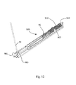
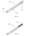
- Figs 9 to 16 the pre-tensioning devices of the cords will be described in detail.
- the screening arrangement 1 is provided with a set of cartridges 900, of which the left-hand one will be described in the following. Corresponding considerations apply to the other cartridge for accommodation in the opposite end of the top element 4. It is noted that in Figs 9 and 10 , some details normally positioned in the top element 4 have been removed for the sake of clarity.
- each cartridge 900 is accommodated inside the top element 4 in the supply condition and mounted condition, namely in a track 448 in the cover 430 of the top element 4.
- the accommodation is releasable, i.e. the cartridge 900 may be removed from the top element 4 without destruction of either part.
- the cartridge 900 may be slidingly engageable with the track 448 positioned inside the top element 4.
- each cartridge 900 comprises, in the embodiment shown, a shoulder portion 901 for abutment against the left-hand end piece 410.
- the cartridge 900 comprises means for engagement with one end of cord 91. Furthermore, as the screening arrangement comprises a set of separate springs, each cartridge 900 is provided with means for holding a spring 910 of the set.
- each spring 910 is a tension spring having a first end 910a and a second end 910b.
- the means for engagement with one end of the cord 91 is provided by the first end 910a of the spring 910 being shaped as an eye.
- the means for holding the spring 910 comprise a stub portion 902, over which the eye of the second end 910b of said spring 910 is placed. Eventually, there is a guidance portion 903 for guiding the spring 910 between the first and second ends 910a, 910b.
- the guidance portion 903 secures the spring 910 during assembly, before the cord 91 has been connected to the spring 910, and during the movement of the spring 910 when the screening arrangement is operated.
- the length of the cartridge 900 exceeds the length of the spring 910 in its extended condition.
- the cartridge 900 has an opening 904 for the passage of the cord 91, the opening having a mouth of smaller dimensions than those of the cord 91. in this manner, it is obtained that the cord 91 is held safely in the opening 904 during normal use but may still be withdrawn from the cartridge 900.
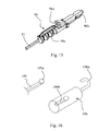
- cord 91 is provided with a first cord end retainer 96 adapted to engage with the engagement means of the cartridge 900.
- these engagement means are, as mentioned, constituted by the eye-shaped first end 910a of the spring 910.
- the retainer 96 comprises an introduction portion 96b and a portion comprising a number of flanges 96c.
- the first cord end retainer 96 may be connected with the cord 91 in any suitable manner but is preferably formed integrally with the cord 91, for instance by moulding.
- the flanges 96c have the additional function of securing retention of the cord inside the retainer 96.
- the material of the retainer shrinks as the temperature of the material is reduced during the cooling off phase. This entails that the material of the retainer is tightened around the cord 91 in a squeezing motion and a secure connection between these two parts is obtained.
- the retainer 96 in the configuration shown in the drawings, i.e.
- the cord 91 is squeezed slightly in the area of the flanges. This, in turn, increases the security against unintended release of the cord from the retainer even further.
- the effect of the squeezing is increased by the number of flanges 96c.
- connection between the cord 191 and the cord end retainer 196 is carried out as a mechanical connection.
- the cord 191 has at its end an enlargement 191a, for instance formed as a local thickening or simply a knot.
- the retainer 196 has a key hole-shaped track 196b, the enlargement 191a fitting into the larger section of the key hole-shaped track.
- the cartridge comprises further openings 906 and 907.
- Opening 907 is made primarily with due regard to the manufacturing conditions, but is also of help during assembly as it may be ascertained that the spring 910 is positioned correctly.
- Opening 906 serves to guide the cord 91 from upstanding portion 905 near the end of the cartridge 900 to the spring 910, the retainer 96 being threadable through for instance the opening 906.
- Fig. 1 the screening arrangement 1 is shown in a supply condition attained at the manufacturer and indicating the condition or state, in which the screening arrangement is supplied and delivered.
- a set of angular brackets 85 is connected to the top rail 440 of the top element 4. This operation is advantageously carried out by a suitable tool to secure that the angular brackets assume correct positions.
- the bottom element 7 is fixed in a predetermined distance from the top element 4 by means of two fittings 10.
- the fittings are identical to each other, and reference will only be made to the left-hand fitting 10 in Fig. 1 .
- the parallel guidance cord system including cords 91, 92 are connected to the other parts of the screening arrangement.
- the cords 91, 92 are guided through the side guidance element 700 connected to the bottom element 7, namely cord 91 through opening 702 near the upper edge 701, and cord 92 through opening 703.
- the first cord end retainer 96 acts as a needle, which is threaded through the openings in the side guidance element 700.
- the other cord end retainer 95 is kept in place and ensures that the cords are not withdrawn from the side guidance element 700 once they have been threaded.
- the cords 91, 92 are connected to the respective cartridge 900, which is subsequently slid into engagement with the track 448 inside the top element 4.
- the cords 91, 92 of the parallel guidance cord system are tightened and secured in the fittings 10 as will be described further below.
- each side rail is brought from a position, in which the side rail is out of alignment with the second longitudinal direction, to a position, in which the side rails is in alignment with the second longitudinal direction, during the step of connecting the side rails to the top rail.
- the bottom element 7 and consequently the side guidance element 700 are kept substantially stationary by means of the fittings 10.
- the side guidance element 700 thus abuts slightly on the back side of the angular bracket 85. All through the above operations the fittings 10 hold the bottom element 7 at its predetermined distance from the top rail 440 of the top element 4.
- the cords 91, 92 of the cord system are also kept tight on the fittings 10, in the embodiment shown by means of T-shaped cord retainers 95.
- each cord 91, 92 i.e. for instance the cord 91 carrying at one end the lower end cord retainer 95, is connected to the respective bracket 93, 94 near the sash bottom piece.
- the engagement between the fitting 10 and the bottom element 7 is released.
- the engagement between the fitting 10 and the top element 4 is released.
- the screening arrangement is in its condition of use. Slight deviations of the above described mounting procedure may, of course, occur.
- Embodiment 2 A screening arrangement according to embodiment 1, wherein the sliding engagement between each cartridge (900) and said track (448) is releasable.
- Embodiment 3 A screening arrangement according to embodiment 2, wherein each cartridge (900) comprises a shoulder portion (901) for abutment against a corresponding portion or part of the top element (4).
- Embodiment 4 A screening arrangement according to any one of the preceding embodiments, wherein the screening arrangement comprises a set of separate springs (910), and wherein each cartridge (900) is provided with means for holding a spring (910).
- each spring (910) is a tension spring having a first end (910a) and a second end (910b), said means for engagement with one end of said cord (91) being provided by the first end (910a) of the spring (910).
- Embodiment 6 A screening arrangement according to embodiment 5, wherein said holding means comprise a stub portion (902) for holding the second end (910b) of said spring (910) and at least one guidance portion (903) for guiding the spring (910) between the first and second ends (910a, 910b).
- said holding means comprise a stub portion (902) for holding the second end (910b) of said spring (910) and at least one guidance portion (903) for guiding the spring (910) between the first and second ends (910a, 910b).
- Embodiment 7 A screening arrangement according to any one of embodiments 4 to 6, wherein the length of the cartridge (900) exceeds the length of the spring (910) in its extended condition.
- Embodiment 8 A screening arrangement according to any one of the preceding embodiments, wherein the cartridge (900) has an opening (904) for the passage of the cord (91), said opening having a mouth of smaller dimensions than those of the cord (91).
Landscapes
- Engineering & Computer Science (AREA)
- Structural Engineering (AREA)
- Architecture (AREA)
- Civil Engineering (AREA)
- Closing And Opening Devices For Wings, And Checks For Wings (AREA)
- Automatic Tape Cassette Changers (AREA)
- Details Or Accessories Of Spraying Plant Or Apparatus (AREA)
- Lift-Guide Devices, And Elevator Ropes And Cables (AREA)
- Conductive Materials (AREA)
- Control Of Indicators Other Than Cathode Ray Tubes (AREA)
- Financial Or Insurance-Related Operations Such As Payment And Settlement (AREA)
- Refuge Islands, Traffic Blockers, Or Guard Fence (AREA)
- Toys (AREA)
- Adornments (AREA)
- Automatic Analysis And Handling Materials Therefor (AREA)
Priority Applications (1)
| Application Number | Priority Date | Filing Date | Title |
|---|---|---|---|
| EP12155308.5A EP2455578B1 (de) | 2007-10-26 | 2007-10-26 | Seilsystem mit Parallelführung |
Applications Claiming Priority (3)
| Application Number | Priority Date | Filing Date | Title |
|---|---|---|---|
| EP07817956A EP2220326B1 (de) | 2007-10-26 | 2007-10-26 | Abschirmanordnung mit einer kassette und parallelführungsschnursystem |
| PCT/DK2007/050158 WO2009052823A1 (en) | 2007-10-26 | 2007-10-26 | A screening arrangement comprising a cartridge and a parallel guidance cord system |
| EP12155308.5A EP2455578B1 (de) | 2007-10-26 | 2007-10-26 | Seilsystem mit Parallelführung |
Related Parent Applications (2)
| Application Number | Title | Priority Date | Filing Date |
|---|---|---|---|
| EP07817956.1 Division | 2007-10-26 | ||
| EP07817956A Division EP2220326B1 (de) | 2007-10-26 | 2007-10-26 | Abschirmanordnung mit einer kassette und parallelführungsschnursystem |
Publications (2)
| Publication Number | Publication Date |
|---|---|
| EP2455578A1 true EP2455578A1 (de) | 2012-05-23 |
| EP2455578B1 EP2455578B1 (de) | 2017-04-19 |
Family
ID=39608210
Family Applications (2)
| Application Number | Title | Priority Date | Filing Date |
|---|---|---|---|
| EP12155308.5A Active EP2455578B1 (de) | 2007-10-26 | 2007-10-26 | Seilsystem mit Parallelführung |
| EP07817956A Active EP2220326B1 (de) | 2007-10-26 | 2007-10-26 | Abschirmanordnung mit einer kassette und parallelführungsschnursystem |
Family Applications After (1)
| Application Number | Title | Priority Date | Filing Date |
|---|---|---|---|
| EP07817956A Active EP2220326B1 (de) | 2007-10-26 | 2007-10-26 | Abschirmanordnung mit einer kassette und parallelführungsschnursystem |
Country Status (6)
| Country | Link |
|---|---|
| EP (2) | EP2455578B1 (de) |
| CN (1) | CN101874143B (de) |
| AT (1) | ATE545758T1 (de) |
| DK (1) | DK2220326T3 (de) |
| PL (2) | PL2220326T3 (de) |
| WO (1) | WO2009052823A1 (de) |
Citations (4)
| Publication number | Priority date | Publication date | Assignee | Title |
|---|---|---|---|---|
| FR2686372A1 (fr) * | 1992-01-21 | 1993-07-23 | Mariton | Mecanisme de compensation pour stores de toiture. |
| WO1998032944A1 (en) | 1997-01-24 | 1998-07-30 | Velux Industri A/S | A universal mounting and parallel guidance arrangement for a window screening device |
| US20020056530A1 (en) * | 2000-11-10 | 2002-05-16 | Butler Edward Maurice Pierce | Display unit |
| EP1447516A2 (de) * | 2003-02-14 | 2004-08-18 | Hunter Douglas Industries B.V. | Seilspanner |
Family Cites Families (1)
| Publication number | Priority date | Publication date | Assignee | Title |
|---|---|---|---|---|
| NL1025225C2 (nl) * | 2004-01-13 | 2005-07-14 | C T R Trading B V | Inrichting voor het ophalen en het laten zakken van een raambekleding. |
-
2007
- 2007-10-26 PL PL07817956T patent/PL2220326T3/pl unknown
- 2007-10-26 WO PCT/DK2007/050158 patent/WO2009052823A1/en not_active Ceased
- 2007-10-26 EP EP12155308.5A patent/EP2455578B1/de active Active
- 2007-10-26 DK DK07817956.1T patent/DK2220326T3/da active
- 2007-10-26 AT AT07817956T patent/ATE545758T1/de active
- 2007-10-26 CN CN2007801016965A patent/CN101874143B/zh not_active Expired - Fee Related
- 2007-10-26 PL PL12155308T patent/PL2455578T3/pl unknown
- 2007-10-26 EP EP07817956A patent/EP2220326B1/de active Active
Patent Citations (4)
| Publication number | Priority date | Publication date | Assignee | Title |
|---|---|---|---|---|
| FR2686372A1 (fr) * | 1992-01-21 | 1993-07-23 | Mariton | Mecanisme de compensation pour stores de toiture. |
| WO1998032944A1 (en) | 1997-01-24 | 1998-07-30 | Velux Industri A/S | A universal mounting and parallel guidance arrangement for a window screening device |
| US20020056530A1 (en) * | 2000-11-10 | 2002-05-16 | Butler Edward Maurice Pierce | Display unit |
| EP1447516A2 (de) * | 2003-02-14 | 2004-08-18 | Hunter Douglas Industries B.V. | Seilspanner |
Also Published As
| Publication number | Publication date |
|---|---|
| EP2220326B1 (de) | 2012-02-15 |
| DK2220326T3 (da) | 2012-05-21 |
| CN101874143B (zh) | 2012-07-04 |
| EP2220326A1 (de) | 2010-08-25 |
| WO2009052823A1 (en) | 2009-04-30 |
| ATE545758T1 (de) | 2012-03-15 |
| EP2455578B1 (de) | 2017-04-19 |
| PL2455578T3 (pl) | 2017-09-29 |
| PL2220326T3 (pl) | 2012-07-31 |
| CN101874143A (zh) | 2010-10-27 |
Similar Documents
| Publication | Publication Date | Title |
|---|---|---|
| US8991468B2 (en) | Window shade | |
| EP2031176B1 (de) | Verankerungsvorrichtung | |
| US20070261801A1 (en) | Assembly to lock a storm curtain adjacent to an opening in a building | |
| KR101385877B1 (ko) | 권취식 방충망 | |
| JP7489596B2 (ja) | スクリーン装置用のサイドガイド | |
| US9004138B2 (en) | Screen device | |
| EP2220328B1 (de) | Abschirmungsanordnung mit einer halterung zur befestigung und verfahren zur befestigung solch einer abschirmungsanordnung | |
| EP2220326B1 (de) | Abschirmanordnung mit einer kassette und parallelführungsschnursystem | |
| EP2982827B1 (de) | Aufrollbare markise | |
| JP3685674B2 (ja) | シャッター | |
| EP2215322B1 (de) | Abschirmanordnung mit frei beweglichem abschirmkörper | |
| CN101099023A (zh) | 遮蔽装置及其安装方法 | |
| CN101874144B (zh) | 包括便于遮蔽体的展示的配件的遮蔽装置和遮蔽装置与改善遮蔽装置的展示的包装的组合体 | |
| EP2476858B1 (de) | Abschirmungsanordnung mit Seitenführungselementen | |
| KR101570982B1 (ko) | 배전반용 안전장치 | |
| EP2963228A1 (de) | Abschirmungsanordnung mit verbesserten mitteln zur montage | |
| JP2007056447A (ja) | ロール網戸 | |
| JP6885723B2 (ja) | シャッター | |
| EP2966253B1 (de) | Abschirmungsanordnung mit verbesserten verbindungsmitteln für querelemente an einer seitenleiste | |
| KR20110000875U (ko) | 아치형 커버를 가진 블라인드용 체결금구 | |
| JP2026034983A (ja) | 屋外用建具取付具及び屋外用建具の取付構造 | |
| WO2021121513A1 (en) | Method for mounting a roller screen, particularly an insect net, and such roller screen | |
| SI23701A (sl) | Zaščitna mreža za strešno okno | |
| HK1122605A (en) | Anchoring device |
Legal Events
| Date | Code | Title | Description |
|---|---|---|---|
| PUAI | Public reference made under article 153(3) epc to a published international application that has entered the european phase |
Free format text: ORIGINAL CODE: 0009012 |
|
| AC | Divisional application: reference to earlier application |
Ref document number: 2220326 Country of ref document: EP Kind code of ref document: P |
|
| AK | Designated contracting states |
Kind code of ref document: A1 Designated state(s): AT BE BG CH CY CZ DE DK EE ES FI FR GB GR HU IE IS IT LI LT LU LV MC MT NL PL PT RO SE SI SK TR |
|
| 17P | Request for examination filed |
Effective date: 20121112 |
|
| 17Q | First examination report despatched |
Effective date: 20160126 |
|
| GRAP | Despatch of communication of intention to grant a patent |
Free format text: ORIGINAL CODE: EPIDOSNIGR1 |
|
| INTG | Intention to grant announced |
Effective date: 20161006 |
|
| GRAJ | Information related to disapproval of communication of intention to grant by the applicant or resumption of examination proceedings by the epo deleted |
Free format text: ORIGINAL CODE: EPIDOSDIGR1 |
|
| GRAS | Grant fee paid |
Free format text: ORIGINAL CODE: EPIDOSNIGR3 |
|
| GRAP | Despatch of communication of intention to grant a patent |
Free format text: ORIGINAL CODE: EPIDOSNIGR1 |
|
| INTC | Intention to grant announced (deleted) | ||
| GRAA | (expected) grant |
Free format text: ORIGINAL CODE: 0009210 |
|
| INTG | Intention to grant announced |
Effective date: 20170227 |
|
| AC | Divisional application: reference to earlier application |
Ref document number: 2220326 Country of ref document: EP Kind code of ref document: P |
|
| AK | Designated contracting states |
Kind code of ref document: B1 Designated state(s): AT BE BG CH CY CZ DE DK EE ES FI FR GB GR HU IE IS IT LI LT LU LV MC MT NL PL PT RO SE SI SK TR |
|
| REG | Reference to a national code |
Ref country code: GB Ref legal event code: FG4D |
|
| REG | Reference to a national code |
Ref country code: CH Ref legal event code: EP |
|
| REG | Reference to a national code |
Ref country code: AT Ref legal event code: REF Ref document number: 886152 Country of ref document: AT Kind code of ref document: T Effective date: 20170515 |
|
| REG | Reference to a national code |
Ref country code: IE Ref legal event code: FG4D |
|
| REG | Reference to a national code |
Ref country code: DE Ref legal event code: R096 Ref document number: 602007050723 Country of ref document: DE |
|
| REG | Reference to a national code |
Ref country code: NL Ref legal event code: MP Effective date: 20170419 |
|
| REG | Reference to a national code |
Ref country code: LT Ref legal event code: MG4D |
|
| REG | Reference to a national code |
Ref country code: AT Ref legal event code: MK05 Ref document number: 886152 Country of ref document: AT Kind code of ref document: T Effective date: 20170419 |
|
| REG | Reference to a national code |
Ref country code: FR Ref legal event code: PLFP Year of fee payment: 11 |
|
| PG25 | Lapsed in a contracting state [announced via postgrant information from national office to epo] |
Ref country code: NL Free format text: LAPSE BECAUSE OF FAILURE TO SUBMIT A TRANSLATION OF THE DESCRIPTION OR TO PAY THE FEE WITHIN THE PRESCRIBED TIME-LIMIT Effective date: 20170419 |
|
| PG25 | Lapsed in a contracting state [announced via postgrant information from national office to epo] |
Ref country code: LT Free format text: LAPSE BECAUSE OF FAILURE TO SUBMIT A TRANSLATION OF THE DESCRIPTION OR TO PAY THE FEE WITHIN THE PRESCRIBED TIME-LIMIT Effective date: 20170419 Ref country code: FI Free format text: LAPSE BECAUSE OF FAILURE TO SUBMIT A TRANSLATION OF THE DESCRIPTION OR TO PAY THE FEE WITHIN THE PRESCRIBED TIME-LIMIT Effective date: 20170419 Ref country code: ES Free format text: LAPSE BECAUSE OF FAILURE TO SUBMIT A TRANSLATION OF THE DESCRIPTION OR TO PAY THE FEE WITHIN THE PRESCRIBED TIME-LIMIT Effective date: 20170419 Ref country code: GR Free format text: LAPSE BECAUSE OF FAILURE TO SUBMIT A TRANSLATION OF THE DESCRIPTION OR TO PAY THE FEE WITHIN THE PRESCRIBED TIME-LIMIT Effective date: 20170720 Ref country code: AT Free format text: LAPSE BECAUSE OF FAILURE TO SUBMIT A TRANSLATION OF THE DESCRIPTION OR TO PAY THE FEE WITHIN THE PRESCRIBED TIME-LIMIT Effective date: 20170419 |
|
| PG25 | Lapsed in a contracting state [announced via postgrant information from national office to epo] |
Ref country code: IS Free format text: LAPSE BECAUSE OF FAILURE TO SUBMIT A TRANSLATION OF THE DESCRIPTION OR TO PAY THE FEE WITHIN THE PRESCRIBED TIME-LIMIT Effective date: 20170819 Ref country code: BG Free format text: LAPSE BECAUSE OF FAILURE TO SUBMIT A TRANSLATION OF THE DESCRIPTION OR TO PAY THE FEE WITHIN THE PRESCRIBED TIME-LIMIT Effective date: 20170719 Ref country code: LV Free format text: LAPSE BECAUSE OF FAILURE TO SUBMIT A TRANSLATION OF THE DESCRIPTION OR TO PAY THE FEE WITHIN THE PRESCRIBED TIME-LIMIT Effective date: 20170419 Ref country code: SE Free format text: LAPSE BECAUSE OF FAILURE TO SUBMIT A TRANSLATION OF THE DESCRIPTION OR TO PAY THE FEE WITHIN THE PRESCRIBED TIME-LIMIT Effective date: 20170419 |
|
| REG | Reference to a national code |
Ref country code: DE Ref legal event code: R097 Ref document number: 602007050723 Country of ref document: DE |
|
| PG25 | Lapsed in a contracting state [announced via postgrant information from national office to epo] |
Ref country code: SK Free format text: LAPSE BECAUSE OF FAILURE TO SUBMIT A TRANSLATION OF THE DESCRIPTION OR TO PAY THE FEE WITHIN THE PRESCRIBED TIME-LIMIT Effective date: 20170419 Ref country code: EE Free format text: LAPSE BECAUSE OF FAILURE TO SUBMIT A TRANSLATION OF THE DESCRIPTION OR TO PAY THE FEE WITHIN THE PRESCRIBED TIME-LIMIT Effective date: 20170419 Ref country code: DK Free format text: LAPSE BECAUSE OF FAILURE TO SUBMIT A TRANSLATION OF THE DESCRIPTION OR TO PAY THE FEE WITHIN THE PRESCRIBED TIME-LIMIT Effective date: 20170419 Ref country code: CZ Free format text: LAPSE BECAUSE OF FAILURE TO SUBMIT A TRANSLATION OF THE DESCRIPTION OR TO PAY THE FEE WITHIN THE PRESCRIBED TIME-LIMIT Effective date: 20170419 Ref country code: RO Free format text: LAPSE BECAUSE OF FAILURE TO SUBMIT A TRANSLATION OF THE DESCRIPTION OR TO PAY THE FEE WITHIN THE PRESCRIBED TIME-LIMIT Effective date: 20170419 |
|
| PLBE | No opposition filed within time limit |
Free format text: ORIGINAL CODE: 0009261 |
|
| STAA | Information on the status of an ep patent application or granted ep patent |
Free format text: STATUS: NO OPPOSITION FILED WITHIN TIME LIMIT |
|
| PG25 | Lapsed in a contracting state [announced via postgrant information from national office to epo] |
Ref country code: IT Free format text: LAPSE BECAUSE OF FAILURE TO SUBMIT A TRANSLATION OF THE DESCRIPTION OR TO PAY THE FEE WITHIN THE PRESCRIBED TIME-LIMIT Effective date: 20170419 |
|
| 26N | No opposition filed |
Effective date: 20180122 |
|
| PG25 | Lapsed in a contracting state [announced via postgrant information from national office to epo] |
Ref country code: SI Free format text: LAPSE BECAUSE OF FAILURE TO SUBMIT A TRANSLATION OF THE DESCRIPTION OR TO PAY THE FEE WITHIN THE PRESCRIBED TIME-LIMIT Effective date: 20170419 Ref country code: MC Free format text: LAPSE BECAUSE OF FAILURE TO SUBMIT A TRANSLATION OF THE DESCRIPTION OR TO PAY THE FEE WITHIN THE PRESCRIBED TIME-LIMIT Effective date: 20170419 |
|
| REG | Reference to a national code |
Ref country code: CH Ref legal event code: PL |
|
| REG | Reference to a national code |
Ref country code: IE Ref legal event code: MM4A |
|
| PG25 | Lapsed in a contracting state [announced via postgrant information from national office to epo] |
Ref country code: LI Free format text: LAPSE BECAUSE OF NON-PAYMENT OF DUE FEES Effective date: 20171031 Ref country code: CH Free format text: LAPSE BECAUSE OF NON-PAYMENT OF DUE FEES Effective date: 20171031 Ref country code: LU Free format text: LAPSE BECAUSE OF NON-PAYMENT OF DUE FEES Effective date: 20171026 |
|
| REG | Reference to a national code |
Ref country code: BE Ref legal event code: MM Effective date: 20171031 |
|
| PG25 | Lapsed in a contracting state [announced via postgrant information from national office to epo] |
Ref country code: BE Free format text: LAPSE BECAUSE OF NON-PAYMENT OF DUE FEES Effective date: 20171031 |
|
| PG25 | Lapsed in a contracting state [announced via postgrant information from national office to epo] |
Ref country code: MT Free format text: LAPSE BECAUSE OF NON-PAYMENT OF DUE FEES Effective date: 20171026 |
|
| REG | Reference to a national code |
Ref country code: FR Ref legal event code: PLFP Year of fee payment: 12 |
|
| PG25 | Lapsed in a contracting state [announced via postgrant information from national office to epo] |
Ref country code: IE Free format text: LAPSE BECAUSE OF NON-PAYMENT OF DUE FEES Effective date: 20171026 |
|
| PG25 | Lapsed in a contracting state [announced via postgrant information from national office to epo] |
Ref country code: HU Free format text: LAPSE BECAUSE OF FAILURE TO SUBMIT A TRANSLATION OF THE DESCRIPTION OR TO PAY THE FEE WITHIN THE PRESCRIBED TIME-LIMIT; INVALID AB INITIO Effective date: 20071026 |
|
| PG25 | Lapsed in a contracting state [announced via postgrant information from national office to epo] |
Ref country code: CY Free format text: LAPSE BECAUSE OF NON-PAYMENT OF DUE FEES Effective date: 20170419 |
|
| PG25 | Lapsed in a contracting state [announced via postgrant information from national office to epo] |
Ref country code: TR Free format text: LAPSE BECAUSE OF FAILURE TO SUBMIT A TRANSLATION OF THE DESCRIPTION OR TO PAY THE FEE WITHIN THE PRESCRIBED TIME-LIMIT Effective date: 20170419 |
|
| PG25 | Lapsed in a contracting state [announced via postgrant information from national office to epo] |
Ref country code: PT Free format text: LAPSE BECAUSE OF FAILURE TO SUBMIT A TRANSLATION OF THE DESCRIPTION OR TO PAY THE FEE WITHIN THE PRESCRIBED TIME-LIMIT Effective date: 20170419 |
|
| PGFP | Annual fee paid to national office [announced via postgrant information from national office to epo] |
Ref country code: PL Payment date: 20210915 Year of fee payment: 15 |
|
| PGFP | Annual fee paid to national office [announced via postgrant information from national office to epo] |
Ref country code: GB Payment date: 20230907 Year of fee payment: 17 |
|
| PGFP | Annual fee paid to national office [announced via postgrant information from national office to epo] |
Ref country code: FR Payment date: 20230921 Year of fee payment: 17 |
|
| PG25 | Lapsed in a contracting state [announced via postgrant information from national office to epo] |
Ref country code: PL Free format text: LAPSE BECAUSE OF NON-PAYMENT OF DUE FEES Effective date: 20221026 |
|
| PGFP | Annual fee paid to national office [announced via postgrant information from national office to epo] |
Ref country code: DE Payment date: 20240904 Year of fee payment: 18 |
|
| GBPC | Gb: european patent ceased through non-payment of renewal fee |
Effective date: 20241026 |
|
| PG25 | Lapsed in a contracting state [announced via postgrant information from national office to epo] |
Ref country code: GB Free format text: LAPSE BECAUSE OF NON-PAYMENT OF DUE FEES Effective date: 20241026 |
|
| PG25 | Lapsed in a contracting state [announced via postgrant information from national office to epo] |
Ref country code: FR Free format text: LAPSE BECAUSE OF NON-PAYMENT OF DUE FEES Effective date: 20241031 |