EP2455665A2 - Chambre de combustion de turbine à gaz dotée d'un dispositif d'amenée d'air de refroidissement - Google Patents
Chambre de combustion de turbine à gaz dotée d'un dispositif d'amenée d'air de refroidissement Download PDFInfo
- Publication number
- EP2455665A2 EP2455665A2 EP11007235A EP11007235A EP2455665A2 EP 2455665 A2 EP2455665 A2 EP 2455665A2 EP 11007235 A EP11007235 A EP 11007235A EP 11007235 A EP11007235 A EP 11007235A EP 2455665 A2 EP2455665 A2 EP 2455665A2
- Authority
- EP
- European Patent Office
- Prior art keywords
- cooling
- combustion chamber
- channel
- gas turbine
- air
- Prior art date
- Legal status (The legal status is an assumption and is not a legal conclusion. Google has not performed a legal analysis and makes no representation as to the accuracy of the status listed.)
- Withdrawn
Links
- 238000001816 cooling Methods 0.000 title claims abstract description 88
- 238000002485 combustion reaction Methods 0.000 title claims abstract description 42
- 239000007789 gas Substances 0.000 claims description 39
- 230000001154 acute effect Effects 0.000 claims description 11
- 230000000694 effects Effects 0.000 description 7
- 238000011144 upstream manufacturing Methods 0.000 description 5
- 238000004140 cleaning Methods 0.000 description 3
- 238000010276 construction Methods 0.000 description 3
- 230000002349 favourable effect Effects 0.000 description 3
- 230000003993 interaction Effects 0.000 description 3
- 239000004576 sand Substances 0.000 description 3
- 230000015572 biosynthetic process Effects 0.000 description 2
- 230000007423 decrease Effects 0.000 description 2
- 230000003247 decreasing effect Effects 0.000 description 2
- 239000000428 dust Substances 0.000 description 2
- 238000005304 joining Methods 0.000 description 2
- 239000002245 particle Substances 0.000 description 2
- 239000000843 powder Substances 0.000 description 2
- 206010013710 Drug interaction Diseases 0.000 description 1
- 238000000149 argon plasma sintering Methods 0.000 description 1
- 230000000903 blocking effect Effects 0.000 description 1
- 238000005219 brazing Methods 0.000 description 1
- 239000000919 ceramic Substances 0.000 description 1
- 230000001419 dependent effect Effects 0.000 description 1
- 238000005553 drilling Methods 0.000 description 1
- 238000009760 electrical discharge machining Methods 0.000 description 1
- 238000011010 flushing procedure Methods 0.000 description 1
- 239000000463 material Substances 0.000 description 1
- 238000005058 metal casting Methods 0.000 description 1
- 238000004021 metal welding Methods 0.000 description 1
- 238000002156 mixing Methods 0.000 description 1
- XLYOFNOQVPJJNP-UHFFFAOYSA-N water Substances O XLYOFNOQVPJJNP-UHFFFAOYSA-N 0.000 description 1
- 238000003466 welding Methods 0.000 description 1
Images

Classifications
-
- F—MECHANICAL ENGINEERING; LIGHTING; HEATING; WEAPONS; BLASTING
- F23—COMBUSTION APPARATUS; COMBUSTION PROCESSES
- F23R—GENERATING COMBUSTION PRODUCTS OF HIGH PRESSURE OR HIGH VELOCITY, e.g. GAS-TURBINE COMBUSTION CHAMBERS
- F23R3/00—Continuous combustion chambers using liquid or gaseous fuel
- F23R3/02—Continuous combustion chambers using liquid or gaseous fuel characterised by the air-flow or gas-flow configuration
- F23R3/04—Air inlet arrangements
- F23R3/06—Arrangement of apertures along the flame tube
-
- F—MECHANICAL ENGINEERING; LIGHTING; HEATING; WEAPONS; BLASTING
- F23—COMBUSTION APPARATUS; COMBUSTION PROCESSES
- F23R—GENERATING COMBUSTION PRODUCTS OF HIGH PRESSURE OR HIGH VELOCITY, e.g. GAS-TURBINE COMBUSTION CHAMBERS
- F23R2900/00—Special features of, or arrangements for continuous combustion chambers; Combustion processes therefor
- F23R2900/03041—Effusion cooled combustion chamber walls or domes
-
- F—MECHANICAL ENGINEERING; LIGHTING; HEATING; WEAPONS; BLASTING
- F23—COMBUSTION APPARATUS; COMBUSTION PROCESSES
- F23R—GENERATING COMBUSTION PRODUCTS OF HIGH PRESSURE OR HIGH VELOCITY, e.g. GAS-TURBINE COMBUSTION CHAMBERS
- F23R2900/00—Special features of, or arrangements for continuous combustion chambers; Combustion processes therefor
- F23R2900/03042—Film cooled combustion chamber walls or domes
-
- Y—GENERAL TAGGING OF NEW TECHNOLOGICAL DEVELOPMENTS; GENERAL TAGGING OF CROSS-SECTIONAL TECHNOLOGIES SPANNING OVER SEVERAL SECTIONS OF THE IPC; TECHNICAL SUBJECTS COVERED BY FORMER USPC CROSS-REFERENCE ART COLLECTIONS [XRACs] AND DIGESTS
- Y02—TECHNOLOGIES OR APPLICATIONS FOR MITIGATION OR ADAPTATION AGAINST CLIMATE CHANGE
- Y02T—CLIMATE CHANGE MITIGATION TECHNOLOGIES RELATED TO TRANSPORTATION
- Y02T50/00—Aeronautics or air transport
- Y02T50/60—Efficient propulsion technologies, e.g. for aircraft
Definitions
- the invention relates to a gas turbine combustion chamber with ade Kunststoffzu Technologyvoriques to be cooled wall of the combustion chamber.
- the invention has for its object to provide ade povertyzu Georgianamiconductor for a gas turbine combustor, which in particular avoids the risk of clogging by foreign particles with a simple structure and reliable operation.
- thede povertyzu classroomvoriques comprises at least one air supply channel, which is arranged with respect to its central axis or flow axis perpendicular to the wall of the combustion chamber or to a tangent surface in the region of the outlet opening of the air supply channel through the wall of the combustion chamber.
- flow axis means either the center axis of a straight, tubular channel, or the three-dimensional center line of the flow channel.
- the air supply channel is flow-connected to at least one cooling channel and thus opens into it.
- the air supply channel has a smaller diameter than the at least one subsequent cooling channel.
- the air supply channel thus forms a throttle or throttle point.
- the invention provides that the cooling channel at a shallow angle, based on its flow axis to the surface of the wall in a Recess of the wall opens. The flow is thus guided at a shallow angle to the wall of the combustion chamber. Furthermore, the invention provides that the cooling channel is designed to form a swirl of the air flowing through.
- the swirl is formed either by an axial offset of the flow axes of the air supply channel and the cooling channel or by a helical shape or helical configuration of the cooling channel itself.
- each other two cooling channels are arranged, which are arranged at an acute angle to each other, based on their flow axes.
- the flows supplied by the two cooling channels thus converge through two mutually adjacent recesses of the combustion chamber wall, as will be described below.
- the two adjacent cooling channels are preferably designed to form an opposite twist of the air flowing through them. It is particularly advantageous if the swirl directions of the two air flows are formed so that the out of the recesses of the supplied through the cooling channels, outflowing air flows to the wall of the combustion chamber.
- the flat angle of the mouth of the cooling channel is preferably between 5 ° and 45 °, preferably between 10 ° and 30 °. An angle of 20 ° is particularly favored. The acute angle between the adjacent cooling channels is inventively cheaper smaller 45 °.
- the distance of the edges of the recesses of the wall, through which the cooling channels open smaller than four diameters of the openings or 2 * (diameter of the first opening + diameter of the second opening).
- the bisector at an acute angle between the two cooling channels in Is arranged substantially in the flow direction of a flow of gases along the wall to be cooled of the combustion chamber.
- the air is thus introduced through a narrowest cross-section, which enters the wall substantially perpendicular to the surface in a slightly larger cooling channel, that a twisted flow is formed, wherein the swirl caused by an offset of the axes of narrowest cross section and welabm channel , the further channel opens at a flat angle on the side facing the hot gas through the surface of the component, always two openings of secondary channels open close to each other and thereby include by their axes at the outlet an acute angle, and the opposite spin of two, close together lying outlet openings, so behaves to each other that the air flows in the area between the two outlet openings in the direction of the wall to be cooled.
- a flat angle to the surface according to the invention is preferably an angle between 5 ° to 45 ° degrees, more preferably 10 ° to 30 °, ideally 20 °.
- Two openings are close together when the spacing of the edges of the openings is less than four diameters of the openings or 2 * (diameter of the first opening + diameter of the second opening).
- An acute angle between the axes is an angle less than 45 °.
- the bisecting line at an acute angle between the two cooling channels opening close to one another is essentially aligned with the direction of flow of the hot gas.
- the closely spaced openings can be supplied with air from the same narrowest cross-section or from two adjacent narrowest sections.
- the further channel may have one or two outlets on the side facing the hot gas.
- the direction of rotation of the heli must be opposite to the two channels opening close to each other on the side facing the hot gas, and so on directed that the air flowing out of the channels between the channels flows in the direction of the wall to be cooled.
- the air can flow through the transverse secondary channel in two directions, and push through the curved shape of the secondary channel in two closely spaced openings on the side facing the hot gas side of the component through the surface, wherein the swirl of the two air streams then behaves in relation to each other such that the air flows between the two openings in the direction of the component to be cooled.
- the axis of the narrowest cross-section must be shifted relative to the axis of the transverse channel so that the narrowest cross-section is displaced in the direction of the opening on the hot gas side.
- the first part of the flow channel which forms the narrowest cross section, stands with its axis substantially locally perpendicular to the surface of the wall, which is penetrated by the flow channel.
- the first part of the flow channel which forms the narrowest cross-section, lies in a plane at an angle to the plane of the second part of the flow channel.
- the cooling openings according to the invention are not subsequently introduced into the wall material, be it a combustion chamber or another component of a gas turbine, but are generated together with the wall which penetrates the opening. This can be done for example by the layer-wise construction of the component by means of laser welding of metal powder or by casting of metal in a mold produced by means of laser sintering of ceramic powder. Alternatively, several sheets can be processed accordingly and then laminated on each other.
- the Fig. 1 shows a schematic representation of a cross section of a gas turbine combustor according to the prior art.
- compressor discharge blades 1 and a combustion chamber outer housing 2 and a combustion chamber inner housing 3 are shown schematically.
- the reference numeral 4 denotes a burner with arm and head
- the reference numeral 5 denotes a combustion chamber head, which is followed by a combustion chamber wall 6, through which the flow is directed to turbine inlet blades 7.
- the supplied cooling air initially flows through an air supply channel 8, which is arranged perpendicular to the combustion chamber wall 6, as this results from the flow arrow shown in the figures respectively.
- the respective air supply channel 8 is provided with a smaller cross-section than a subsequent cooling channel.
- the air supply channel 8 forms a throttle point for the further flowing air in the at least one cooling channel.
- the cooling channels 9 and the air supply channel 8 are each formed so that a swirl of the air flow results, as shown by the arrows in the figures.
- the figures also show the combustion chamber wall 6 of the combustion chamber and the hot gas air flow running along the wall. It follows that the cooling channels 9 are each arranged at a shallow angle to the combustion chamber wall 6. Furthermore, adjacent cooling channels 9 are arranged at an acute angle to each other, so that the exiting thrown air flows meet each convergent. The twist direction is chosen so that, as shown for example in Fig. 9, the air flow against the combustion chamber wall 6 applies.
- the Fig. 2 shows an embodiment with opposite spin from two adjacent narrowest cross sections (air supply channels 8) with downstream shifted axis of the narrowest cross section with respect to the transverse channel (cooling channel 9) in the combustion chamber wall 6. It follows that the illustrations of Fig. 2 to 6 each are schematic perspective views. Shown is thus the inner surface of the air supply channel 8 and the cooling channel 9 and the air in the cooling channel 9. The exterior of the combustion chamber wall 6 was removed on the side facing away from the hot gas. It thus results that two substantially U-shaped cooling channels 9 are provided.
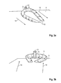
- the Fig. 3B shows the opposite twist from both ends of the cooling channel 9, supplied by the same narrowest cross-section of the cooling channel 8 with upstream axis of the air supply channel 8 narrowest cross-section with respect to the transverse region channel of the cooling channels 9 in the wall (view from upstream).
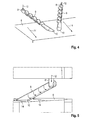
- the Fig. 4 shows a further embodiment with opposite spin from two opposing heli, which form the cooling channels 9.
- the twist need not be generated by a skewed inlet opening, but is determined by the direction of rotation of the helix.
- a skewed entry opening can support the formation of a twisted flow in the cooling channel 9.
- Both outlet openings 10 are aligned at a small angle to the hot gas flow (view from downstream).
- the Fig. 5 shows an embodiment with a twist in a cylindrical Effusionsö réelle 10 (recess of the combustion chamber wall 6) with windshaft inlet opening as the narrowest cross-section (air supply channel 8).
- two ports of opposite spin are aligned at a small angle to the hot gas flow, so that the flow between the ports flows in the direction of the combustion chamber wall 6 to be cooled. This is achieved when the feed opening in each case on the outside (not between) the two continuing cooling channels 9 are arranged.
- the Figure 5 shows a view from upstream.
- Fig. 6 shows a further embodiment with a variant with running parallel in the wall continuing cooling channel 9, this windshield slit as the narrowest cross-section and employed Auslassdiffuser.
- two cooling channels 9 with opposite twist aligned with a small angle to the hot gas flow combined so that the flow between the openings in the direction of the wall 6 to be cooled flows. This is achieved when the feed opening 10 are each arranged on the outside (ie not between) the two continuing cooling channels 9.
- the cooling channel 9 does not necessarily have to be round.
- Fig. 6 a geometry variant is shown, which allows joining the wall of two sheets.
- the first continuing Cooling channel 9 made in the one surface of a sheet and after joining by eg brazing or welding, the skewed inlet opening (air supply channel 8) is introduced by, for example, drilling or spark erosion through the second sheet.
- the Auslassdiffuser 11 in the other side of the first sheet can be introduced at a suitable time in the single sheet or in the already joined laminate of two sheets.
- the Fig. 6 shows a view from upstream.
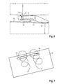
- Fig. 7 shows the principle of the interaction of two adjacent openings 10 with advantageous formation of the swirls: between the two openings 10, the air flows through the swirl in the direction of the wall to be cooled 6 and thereby creates even at steeper exit angle or higher Ausblaseraten to the wall to be cooled ,
Landscapes
- Engineering & Computer Science (AREA)
- Chemical & Material Sciences (AREA)
- Combustion & Propulsion (AREA)
- Mechanical Engineering (AREA)
- General Engineering & Computer Science (AREA)
- Turbine Rotor Nozzle Sealing (AREA)
Applications Claiming Priority (1)
| Application Number | Priority Date | Filing Date | Title |
|---|---|---|---|
| DE102010051638A DE102010051638A1 (de) | 2010-11-17 | 2010-11-17 | Gasturbinenbrennkammer mit einer Kühlluftzuführvorrichtung |
Publications (2)
| Publication Number | Publication Date |
|---|---|
| EP2455665A2 true EP2455665A2 (fr) | 2012-05-23 |
| EP2455665A3 EP2455665A3 (fr) | 2017-11-22 |
Family
ID=44675402
Family Applications (1)
| Application Number | Title | Priority Date | Filing Date |
|---|---|---|---|
| EP11007235.2A Withdrawn EP2455665A3 (fr) | 2010-11-17 | 2011-09-06 | Chambre de combustion de turbine à gaz dotée d'un dispositif d'amenée d'air de refroidissement |
Country Status (3)
| Country | Link |
|---|---|
| US (1) | US9016067B2 (fr) |
| EP (1) | EP2455665A3 (fr) |
| DE (1) | DE102010051638A1 (fr) |
Cited By (1)
| Publication number | Priority date | Publication date | Assignee | Title |
|---|---|---|---|---|
| EP2759772A1 (fr) * | 2013-01-23 | 2014-07-30 | Honeywell International Inc. | Chambres de combustion avec trous d'effusion de forme complexe |
Families Citing this family (11)
| Publication number | Priority date | Publication date | Assignee | Title |
|---|---|---|---|---|
| EP3066391B1 (fr) * | 2013-11-05 | 2019-01-16 | United Technologies Corporation | Panneau de paroi flottante de chambre de combustion refroidie |
| EP2949871B1 (fr) * | 2014-05-07 | 2017-03-01 | United Technologies Corporation | Segment d'aube variable |
| PL3550133T3 (pl) | 2014-12-17 | 2022-08-01 | Pratt & Whitney Canada Corp. | Przewód wydechowy do silnika turbogazowego |
| FR3037107B1 (fr) * | 2015-06-03 | 2019-11-15 | Safran Aircraft Engines | Paroi annulaire de chambre de combustion a refroidissement optimise |
| US10871075B2 (en) | 2015-10-27 | 2020-12-22 | Pratt & Whitney Canada Corp. | Cooling passages in a turbine component |
| US10533749B2 (en) * | 2015-10-27 | 2020-01-14 | Pratt & Whitney Cananda Corp. | Effusion cooling holes |
| DE102016116222A1 (de) * | 2016-08-31 | 2018-03-01 | Rolls-Royce Deutschland Ltd & Co Kg | Gasturbine |
| DE102017202177A1 (de) | 2017-02-10 | 2018-08-16 | Rolls-Royce Deutschland Ltd & Co Kg | Wandbauteil einer Gasturbine mit verbesserter Kühlung |
| CN108194203A (zh) * | 2017-12-19 | 2018-06-22 | 中国船舶重工集团公司第七0三研究所 | 一种用于工业燃气轮机箱装体的分支冷却结构 |
| US20220325891A1 (en) | 2021-04-12 | 2022-10-13 | General Electric Company | Dilution horn pair for a gas turbine engine combustor |
| KR20230101582A (ko) * | 2021-12-29 | 2023-07-06 | 한화에어로스페이스 주식회사 | 연소기 |
Citations (2)
| Publication number | Priority date | Publication date | Assignee | Title |
|---|---|---|---|---|
| GB2412411A (en) | 2004-03-25 | 2005-09-28 | Rolls Royce Plc | A cooling arrangement |
| EP1803897A2 (fr) | 2005-10-26 | 2007-07-04 | Rolls-Royce plc | Refroidissement pour la paroi d'une aube de turbine à gaz |
Family Cites Families (15)
| Publication number | Priority date | Publication date | Assignee | Title |
|---|---|---|---|---|
| US4080095A (en) * | 1976-09-02 | 1978-03-21 | Westinghouse Electric Corporation | Cooled turbine vane |
| CH634128A5 (de) * | 1978-06-13 | 1983-01-14 | Bbc Brown Boveri & Cie | Kuehlvorrichtung an einer wand. |
| US4302940A (en) * | 1979-06-13 | 1981-12-01 | General Motors Corporation | Patterned porous laminated material |
| US5584651A (en) * | 1994-10-31 | 1996-12-17 | General Electric Company | Cooled shroud |
| US5738493A (en) * | 1997-01-03 | 1998-04-14 | General Electric Company | Turbulator configuration for cooling passages of an airfoil in a gas turbine engine |
| US6145319A (en) * | 1998-07-16 | 2000-11-14 | General Electric Company | Transitional multihole combustion liner |
| US6237344B1 (en) * | 1998-07-20 | 2001-05-29 | General Electric Company | Dimpled impingement baffle |
| CA2288557C (fr) * | 1998-11-12 | 2007-02-06 | Mitsubishi Heavy Industries, Ltd. | Montage de refroidissement de chambre de combustion a turbine a gaz |
| US6427446B1 (en) * | 2000-09-19 | 2002-08-06 | Power Systems Mfg., Llc | Low NOx emission combustion liner with circumferentially angled film cooling holes |
| EP1475567A1 (fr) * | 2003-05-08 | 2004-11-10 | Siemens Aktiengesellschaft | Structure stratifiée et procédé de fabrication de la structure stratifiée |
| US7658590B1 (en) * | 2005-09-30 | 2010-02-09 | Florida Turbine Technologies, Inc. | Turbine airfoil with micro-tubes embedded with a TBC |
| US8387396B2 (en) * | 2007-01-09 | 2013-03-05 | General Electric Company | Airfoil, sleeve, and method for assembling a combustor assembly |
| US20090169394A1 (en) * | 2007-12-28 | 2009-07-02 | General Electric Company | Method of forming cooling holes and turbine airfoil with hybrid-formed cooling holes |
| GB2465337B (en) * | 2008-11-12 | 2012-01-11 | Rolls Royce Plc | A cooling arrangement |
| JP5653705B2 (ja) * | 2010-09-30 | 2015-01-14 | 三菱重工業株式会社 | 回収式空気冷却ガスタービン燃焼器冷却構造 |
-
2010
- 2010-11-17 DE DE102010051638A patent/DE102010051638A1/de not_active Withdrawn
-
2011
- 2011-09-06 EP EP11007235.2A patent/EP2455665A3/fr not_active Withdrawn
- 2011-10-18 US US13/275,805 patent/US9016067B2/en not_active Expired - Fee Related
Patent Citations (2)
| Publication number | Priority date | Publication date | Assignee | Title |
|---|---|---|---|---|
| GB2412411A (en) | 2004-03-25 | 2005-09-28 | Rolls Royce Plc | A cooling arrangement |
| EP1803897A2 (fr) | 2005-10-26 | 2007-07-04 | Rolls-Royce plc | Refroidissement pour la paroi d'une aube de turbine à gaz |
Cited By (2)
| Publication number | Priority date | Publication date | Assignee | Title |
|---|---|---|---|---|
| EP2759772A1 (fr) * | 2013-01-23 | 2014-07-30 | Honeywell International Inc. | Chambres de combustion avec trous d'effusion de forme complexe |
| US9765968B2 (en) | 2013-01-23 | 2017-09-19 | Honeywell International Inc. | Combustors with complex shaped effusion holes |
Also Published As
| Publication number | Publication date |
|---|---|
| DE102010051638A1 (de) | 2012-05-24 |
| US20120117973A1 (en) | 2012-05-17 |
| US9016067B2 (en) | 2015-04-28 |
| EP2455665A3 (fr) | 2017-11-22 |
Similar Documents
| Publication | Publication Date | Title |
|---|---|---|
| EP2455665A2 (fr) | Chambre de combustion de turbine à gaz dotée d'un dispositif d'amenée d'air de refroidissement | |
| DE2656151C2 (de) | Vorrichtung zum Abtrennen von Festkörperverunreinigungen aus einem Gasstrom | |
| DE69917655T2 (de) | System zur dämpfung akustischer schwingungen in einer brennkammer | |
| DE112018002876T5 (de) | Systeme und Verfahren zum Mischen von Abgasen und Reduktionsmittel in einem Nachbehandlungssystem | |
| EP1488077B1 (fr) | Aube de turbine refroidie | |
| DE102010010128A1 (de) | Flugzeugtriebwerk mit optimiertem Ölwärmetauscher | |
| EP2233836A1 (fr) | Générateur de torsion, procédé destiné à empêcher des retours de flammes dans un brûleur, doté d'au moins un générateur de torsion et d'un brûleur | |
| DE102005037026A1 (de) | Kavitationsmischer | |
| DE102010002044A1 (de) | Brennstoffdüse mit aerodynamisch geformten, spiralförmigen Umlenkschaufeln | |
| EP2730771B1 (fr) | Buse pour moteur à turbine à gaz dotée de dispositifs de guidage | |
| EP1981622B2 (fr) | Procédé et dispositif pour mélanger un fluide gazeux à un flux gazeux important, notamment pour introduire un agent réducteur dans un gaz de combustion contenant des oxydes d'azote | |
| EP4313365B1 (fr) | Séparateur d'eau avec un élément d'étranglement, utilisation d'un séparateur d'eau et système de piles à combustible avec un séparateur d'eau | |
| EP3234337A1 (fr) | Conduite d'air pour une tubulure d'admission de moteur à combustion interne, en particulier d'un véhicule à moteur | |
| DE69603715T2 (de) | Venturi mischvorrichtung | |
| CH703225A2 (de) | Austrittsdiffusor eines Verdichters in einer Gasturbine. | |
| DE102004042295A1 (de) | Rotor für ein Triebwerk | |
| DE102016207212A1 (de) | Leitschaufelkranz für eine Strömungsmaschine | |
| EP1288435A2 (fr) | Aube de turbine avec au moins un orifice de refroidissement | |
| EP2225467B1 (fr) | Appareil de production de rotation et turbocompresseur équipé d'un tel appareil | |
| DE102017118583B4 (de) | Anordnung von Stützstreben in einem abstromseitigen Ringraum einer Gasturbine | |
| DE202014105403U1 (de) | Drallkörper und Brenner mit Drallkörper | |
| DE102008060943B4 (de) | Mehrflutiges Turbinengehäuse | |
| DE102010010790A1 (de) | Fluidischer Oszillator | |
| EP2889451B1 (fr) | Dispositif de refroidissement d'une paroi d'un composant | |
| EP4296489B1 (fr) | Entrée d'air |
Legal Events
| Date | Code | Title | Description |
|---|---|---|---|
| PUAI | Public reference made under article 153(3) epc to a published international application that has entered the european phase |
Free format text: ORIGINAL CODE: 0009012 |
|
| AK | Designated contracting states |
Kind code of ref document: A2 Designated state(s): AL AT BE BG CH CY CZ DE DK EE ES FI FR GB GR HR HU IE IS IT LI LT LU LV MC MK MT NL NO PL PT RO RS SE SI SK SM TR |
|
| AX | Request for extension of the european patent |
Extension state: BA ME |
|
| PUAL | Search report despatched |
Free format text: ORIGINAL CODE: 0009013 |
|
| AK | Designated contracting states |
Kind code of ref document: A3 Designated state(s): AL AT BE BG CH CY CZ DE DK EE ES FI FR GB GR HR HU IE IS IT LI LT LU LV MC MK MT NL NO PL PT RO RS SE SI SK SM TR |
|
| AX | Request for extension of the european patent |
Extension state: BA ME |
|
| RIC1 | Information provided on ipc code assigned before grant |
Ipc: F23R 3/06 20060101AFI20171013BHEP |
|
| STAA | Information on the status of an ep patent application or granted ep patent |
Free format text: STATUS: THE APPLICATION IS DEEMED TO BE WITHDRAWN |
|
| 18D | Application deemed to be withdrawn |
Effective date: 20180404 |