EP2455667A2 - Dispositif de commande pour un appareil ménager et appareil ménager, notamment pour la préparation d'aliments, doté d'un dispositif de commande - Google Patents
Dispositif de commande pour un appareil ménager et appareil ménager, notamment pour la préparation d'aliments, doté d'un dispositif de commande Download PDFInfo
- Publication number
- EP2455667A2 EP2455667A2 EP11187440A EP11187440A EP2455667A2 EP 2455667 A2 EP2455667 A2 EP 2455667A2 EP 11187440 A EP11187440 A EP 11187440A EP 11187440 A EP11187440 A EP 11187440A EP 2455667 A2 EP2455667 A2 EP 2455667A2
- Authority
- EP
- European Patent Office
- Prior art keywords
- operating device
- operating
- receptacle
- strip element
- plane
- Prior art date
- Legal status (The legal status is an assumption and is not a legal conclusion. Google has not performed a legal analysis and makes no representation as to the accuracy of the status listed.)
- Withdrawn
Links
- 238000010411 cooking Methods 0.000 description 7
- 230000006870 function Effects 0.000 description 4
- 230000001960 triggered effect Effects 0.000 description 2
- 206010003830 Automatism Diseases 0.000 description 1
- 230000000694 effects Effects 0.000 description 1
- 210000003746 feather Anatomy 0.000 description 1
- 238000005286 illumination Methods 0.000 description 1
- 230000008447 perception Effects 0.000 description 1
- 230000036316 preload Effects 0.000 description 1
Images


Classifications
-
- G—PHYSICS
- G05—CONTROLLING; REGULATING
- G05G—CONTROL DEVICES OR SYSTEMS INSOFAR AS CHARACTERISED BY MECHANICAL FEATURES ONLY
- G05G9/00—Manually-actuated control mechanisms provided with one single controlling member co-operating with two or more controlled members, e.g. selectively, simultaneously
- G05G9/02—Manually-actuated control mechanisms provided with one single controlling member co-operating with two or more controlled members, e.g. selectively, simultaneously the controlling member being movable in different independent ways, movement in each individual way actuating one controlled member only
- G05G9/04—Manually-actuated control mechanisms provided with one single controlling member co-operating with two or more controlled members, e.g. selectively, simultaneously the controlling member being movable in different independent ways, movement in each individual way actuating one controlled member only in which movement in two or more ways can occur simultaneously
- G05G9/047—Manually-actuated control mechanisms provided with one single controlling member co-operating with two or more controlled members, e.g. selectively, simultaneously the controlling member being movable in different independent ways, movement in each individual way actuating one controlled member only in which movement in two or more ways can occur simultaneously the controlling member being movable by hand about orthogonal axes, e.g. joysticks
-
- F—MECHANICAL ENGINEERING; LIGHTING; HEATING; WEAPONS; BLASTING
- F24—HEATING; RANGES; VENTILATING
- F24C—DOMESTIC STOVES OR RANGES ; DETAILS OF DOMESTIC STOVES OR RANGES, OF GENERAL APPLICATION
- F24C7/00—Stoves or ranges heated by electric energy
- F24C7/08—Arrangement or mounting of control or safety devices
- F24C7/082—Arrangement or mounting of control or safety devices on ranges, e.g. control panels, illumination
- F24C7/085—Arrangement or mounting of control or safety devices on ranges, e.g. control panels, illumination on baking ovens
-
- G—PHYSICS
- G01—MEASURING; TESTING
- G01G—WEIGHING
- G01G1/00—Weighing apparatus involving the use of a counterweight or other counterbalancing mass
- G01G1/02—Pendulum-weight apparatus
- G01G1/04—Pendulum-weight apparatus the pendulum having a fixed pivot axis
-
- H—ELECTRICITY
- H01—ELECTRIC ELEMENTS
- H01H—ELECTRIC SWITCHES; RELAYS; SELECTORS; EMERGENCY PROTECTIVE DEVICES
- H01H25/00—Switches with compound movement of handle or other operating part
- H01H25/002—Switches with compound movement of handle or other operating part having an operating member rectilinearly slidable in different directions
-
- A—HUMAN NECESSITIES
- A47—FURNITURE; DOMESTIC ARTICLES OR APPLIANCES; COFFEE MILLS; SPICE MILLS; SUCTION CLEANERS IN GENERAL
- A47L—DOMESTIC WASHING OR CLEANING; SUCTION CLEANERS IN GENERAL
- A47L15/00—Washing or rinsing machines for crockery or tableware
- A47L15/42—Details
- A47L15/4293—Arrangements for programme selection, e.g. control panels; Indication of the selected programme, programme progress or other parameters of the programme, e.g. by using display panels
-
- G—PHYSICS
- G05—CONTROLLING; REGULATING
- G05G—CONTROL DEVICES OR SYSTEMS INSOFAR AS CHARACTERISED BY MECHANICAL FEATURES ONLY
- G05G9/00—Manually-actuated control mechanisms provided with one single controlling member co-operating with two or more controlled members, e.g. selectively, simultaneously
- G05G9/02—Manually-actuated control mechanisms provided with one single controlling member co-operating with two or more controlled members, e.g. selectively, simultaneously the controlling member being movable in different independent ways, movement in each individual way actuating one controlled member only
- G05G9/04—Manually-actuated control mechanisms provided with one single controlling member co-operating with two or more controlled members, e.g. selectively, simultaneously the controlling member being movable in different independent ways, movement in each individual way actuating one controlled member only in which movement in two or more ways can occur simultaneously
- G05G9/047—Manually-actuated control mechanisms provided with one single controlling member co-operating with two or more controlled members, e.g. selectively, simultaneously the controlling member being movable in different independent ways, movement in each individual way actuating one controlled member only in which movement in two or more ways can occur simultaneously the controlling member being movable by hand about orthogonal axes, e.g. joysticks
- G05G2009/04703—Mounting of controlling member
- G05G2009/04733—Mounting of controlling member with a joint having a nutating disc, e.g. forced by a spring
-
- G—PHYSICS
- G05—CONTROLLING; REGULATING
- G05G—CONTROL DEVICES OR SYSTEMS INSOFAR AS CHARACTERISED BY MECHANICAL FEATURES ONLY
- G05G5/00—Means for preventing, limiting or returning the movements of parts of a control mechanism, e.g. locking controlling member
- G05G5/05—Means for returning or tending to return controlling members to an inoperative or neutral position, e.g. by providing return springs or resilient end-stops
-
- H—ELECTRICITY
- H01—ELECTRIC ELEMENTS
- H01H—ELECTRIC SWITCHES; RELAYS; SELECTORS; EMERGENCY PROTECTIVE DEVICES
- H01H21/00—Switches operated by an operating part in the form of a pivotable member acted upon directly by a solid body, e.g. by a hand
- H01H21/02—Details
- H01H21/025—Light-emitting indicators
-
- H—ELECTRICITY
- H01—ELECTRIC ELEMENTS
- H01H—ELECTRIC SWITCHES; RELAYS; SELECTORS; EMERGENCY PROTECTIVE DEVICES
- H01H21/00—Switches operated by an operating part in the form of a pivotable member acted upon directly by a solid body, e.g. by a hand
- H01H21/02—Details
- H01H21/18—Movable parts; Contacts mounted thereon
- H01H21/22—Operating parts, e.g. handle
- H01H21/24—Operating parts, e.g. handle biased to return to normal position upon removal of operating force
Definitions
- the invention relates to an operating device for a domestic appliance, which has an operating element that is movably arranged in a receptacle of the operating device and, depending on a defined movement of the operating element in the receptacle, an operating condition setting of the household appliance can be carried out.
- an operating device for a domestic appliance such as an oven
- a round disc which is thus formed as a flat cylinder
- This disc is partially recessed in a receptacle of the operating device and thus arranged in the housing and can be rotated by touching the front of a user, usually more than 360 °.
- these embodiments of operating devices are very space-consuming. Due to the size of the circular disk, this control element extends very far into the interior of the operating device. In addition to a very large footprint these controls are also limited in user friendliness.
- the operating element is a plate-shaped strip element which has an arcuate front side which extends outward beyond a front opening of the receptacle.
- the plate-shaped strip element is designed in the form of a ring section.
- This allows a particularly space-minimized design while still maintaining high functionality of the possibility of operating the control.
- Especially the possibility of the direction of movement and thus the ease of operation of the control element can be particularly favored by this very specific shape design of the control.
- the quasi-rotary movement can be maintained around a radius.
- this rotational movement sector within which the operating element is rotatable about the center with respect to the radius of the arcuate front side, corresponds to the area with which the arcuate front side extends out of the receptacle of the operating device in its basic position.
- the user must therefore over the entire operating distance, which can perform the maximum control, do not drop off several times and touch the control again on the front to continue to turn. Rather, he can go through or press the entire maximum movement distance of the control element with a single touch and rotation of the control.
- the operating element is movable in the receptacle in a first plane, which is formed by the plane in which the strip element extends.
- this plate-shaped strip element is therefore movable on a curved path in order to be able to carry out an operating condition setting.
- the possibility of movement in the first plane is a pivoting movement on an arcuate path.
- the operating element has at least one guide pin, which engages in a movement of the control element in the recording in a guide slot of the recording.
- the guide slot is formed on the back of the receptacle. This ensures a particularly reliable movement of the control element on the curved path and also ensures the reliable haptic perception of the attacks on the sheet web ends.
- the operating element is held by a spring in a basic position of the recording and biased at a deflection in the first plane from the basic position, the spring so that when you release the control element an automatic return of the control element in the starting position by the Spring is effected. It is thus almost created an automatism that defines the control element and repeatedly returns to the basic position. This also wrong settings can be avoided.
- the operating element is movable in the receptacle of a second plane, which is oriented perpendicular to the plane in which the strip element extends.
- a second possibility of movement in particular in the form of tilting upwards or downwards, can be ensured in particular as well.
- the plate-shaped strip element or in particular the ring section can thereby also be tilted upwards or tilted down to carry out operating condition settings.
- operating condition settings both the selection of functional subunits of the domestic appliance and the setting of operating parameters of such functional subunits are understood.
- the operating condition setting can be understood as switching the household appliance on or off as well as setting a timer function.
- the possibilities of movement in a second plane is a tilting movement.
- the tilting movement takes place within an angular interval of less than 30 °, in particular less than 15 °.
- tilting can therefore preferably take place by a maximum angle of 10 ° upwards and an angle of at most 10 ° downwards.
- the operating element has at least one guide pin which engages the movement guidance of the operating element in the receptacle into a further guide slot of the receptacle.
- the spring is biased, so that when you release the control element an automatic return of the control element in the basic position the spring is effected.
- a light emission region is formed on the front side of the operating element. In this regard, thus illuminating the Operating element at specific locations. In addition, information for a user can be displayed specifically.
- the light emission region can be activated as a function of an actuation type of the operating element and / or is designed to generate light signals of different light color and / or pulsed light signals depending on an actuation mode of the operating element in the activated state. This allows very specific information to be communicated to the user easily and quickly as well as intuitively perceptible.
- the light emission region is strip-shaped and / or extends over the entire width of the front side.
- the device changes caused by the movements of the operating element of an operating parameter of the domestic appliance are displayed in a further display unit.
- an operating element is thus formed as a ring section or circular arc element, which is movable in horizontal deflection in each direction, preferably by an angle ⁇ 10 ° to a defined end position.
- at least one mechanical or electromechanical component is located along the described circular arc and / or at its end position, which makes it possible to detect the switching signal triggered by the operating element and the associated operating condition setting, such as a value setting of an operating parameter, such as a baking oven temperature, or to allow the selection of an operating function or a functional subunit of the oven, such as a cooking zone or the operation of the cooking chamber.
- the operating element is preferably spring-mounted in both horizontal directions.
- the operating element after which it has been moved out of its basic position or released when the end point is reached, automatically moves back into its central starting position or basic position. If, on the other hand, the operating element is still held there by the user after reaching the switching point or the end position, switching signals are continuously transmitted until the operating element is released. By such a configuration can then be achieved that the value adjustment continues to run until the control element is released again. This is particularly advantageous if a larger value difference is to be set.
- the possibility of movement can also take place in a second plane, and thus in particular in the vertical direction.
- a tilting movement in both directions is provided in each case by an angle of less than 5 °, in particular 3 °.
- a mechanical or electromechanical component of the operating device is arranged at the respective tilted end positions, with which it is possible to detect the switch signal triggered by the operating element and to trigger the associated operating condition setting.
- the further advantageous embodiments as they have been explained for the possibility of movement in the first plane and thus given in horizontal deflection, are also provided accordingly for this movement possibility in the second level. For example, holding the operating element in a tilted end position by a user can also be carried out here in order to set a larger difference in value, so that, for example, setting the time for larger values is fast and user-friendly.
- the preferably existing illuminated ring or light strip can be permanently illuminated when the domestic appliance is switched on. It can also be provided that this illuminated ring or this luminous emission area always lights up when the operating element is actuated horizontally or vertically.
- Light sources may preferably be provided as light sources, which are then arranged in the operating device, in particular in the operating element. These are very compact, bright and very energy-saving operable. It can also be provided that the functional light is used to the effect that the user who wants to make a certain setting on his home appliance, by temporarily lighting the control element is given an indication of the settings to be made.
- control element adjacent to the control element further controls, for example in the form of touch-sensitive panels or buttons or the like are provided.
- the invention relates to a domestic appliance, in particular for preparing food, in particular an oven, with an operating device according to the invention in an advantageous embodiment thereof.
- Fig. 1 is a simplified schematic representation of a baking oven 1 shown, which has cooking zones 2, 3, 4 and 5.
- a cooking chamber 6 is formed, which can be closed by a door 7, which has a front handle 8.
- a control panel 9 is arranged above the door 7, which has an operating device 10.
- the operating device 10 comprises at least one operating element 11, which will be explained in more detail below.
- a display unit 12 is arranged in the control panel 9. Both position and design of the operating device 9 is merely exemplary.
- Fig. 2 is a partial section of the oven 1 in the region of the control element 11 is shown in perspective.
- the control panel 9 is shown with a front side 13.
- the operating device 10 comprises a receptacle 14 which has an opening on the front side, the opening being equal to an opening 15 in the front side 13 of the control panel 9. This is rectangular and thus, so to speak, forms a slot-like opening.
- the operating element 11 is arranged and positioned so that it protrudes forward over the opening 15.
- the operating element 11 has a front side 16, which is arcuately curved.
- the operating element 11 is designed as a plate-shaped strip part, which in particular forms a ring section.
- a light emission region 17 is formed in the front side 16, which in the exemplary embodiment is designed as a horizontal strip over the entire width of the front side 16, which protrudes forward from the receptacle 14 and the opening 15.
- Fig. 3 is a schematic representation of a front view of the operating device 10 in particular in the region of the operating element 11 is shown.
- Fig. 4 is (in the cross-sectional representation and thus in a sectional plane perpendicular to the plane of the figure in a representation according to Fig. 3 according to the section line IV-IV), the execution in Fig. 3 shown.
- the one ring section performing control 11 can be seen.
- the arcuate configuration of the front side 16 is shown.
- the receptacle 14 represents a free space in which the operating element 11 in the illustration in Fig. 4 in the plane of the figure according to the arrow P1 is pivoted.
- Fig. 4 If the basic position of the control element 11 is shown.
- the pivoting in a first plane which in the illustration in Fig. 4 the figure plane is, led.
- the stops and the aforementioned angular ranges for the pivoting are defined and specified.
- the curved path 24 is defined, in particular, starting from a center, not shown, of the annular section of the control element 11, wherein a corresponding radius path, which then represents the curved path 24, is defined in this center.
- the operating element 11 is held by means of springs 25 and 26 in the receptacle 14.
- springs 25 and 26 are preferably formed as spiral springs whose longitudinal axes extend substantially along the arcuate path 24.
- the springs 25 and 26 are preferably recessed in recesses in the control element 11, so that the entire configuration is very compact and space-minimized.
- the springs 25 and 26 are quasi held in a cage by this arrangement. As can be seen, the springs 25 and 26 are supported on boundary walls of the guide slots 19 and 20.
- Fig. 5 a further sectional view shown in cross section. This concerns in the representation in Fig. 4 a cross section along the section line VV.
- the cutting area is therefore the same as in Fig. 4 , where in Fig. 5 the operating element is shown in a first operating state.
- control element 11 has been pivoted to the left and out of the basic position according to the arrow P2 and moved along the arcuate path 24. This takes place until the left-side end 27 of the operating element 11 has arrived at its end position in the receptacle 14. It contacts an electrical switch 28, which is arranged on the rear side 18 of the receptacle 14. This generates the appropriate switching signals for the desired operating condition setting.
- a control unit not shown accordingly.
- the desired operating condition setting for example, the selection of one of the cooking zones 2 to 5 and / or the cooking chamber 6 can be done. If such a functional part unit has already been selected, on the other hand it can be provided that by the actuation as shown in FIG Fig. 5 shown is an operating parameter of this selected Function subunit is set by value. For example, then the temperature can be adjusted. In this context, it can also be provided that when setting large value differences, the operating element 11 in the in Fig.
- Fig. 6 is a supplementary representation of a further sectional view in cross section in Fig. 3 shown. In this case, a sectional view along the section line VI-VI is shown. In contrast to the representation according to Fig. 5 Here, a second operating direction of the operating element 11 is shown, so that starting from the illustration in FIG Fig. 4 a deflection in the other direction according to the arrow P3 is done. Here, too, the end position is shown and also here, a further switching element 29 is arranged on the rear wall 18 of the receptacle 14, which detects the contacted end position of the operating element 11 and the associated and desired operating condition setting.
- the two switching elements 28 and 29 may be simple electrical contacts but on the other hand also sensors.
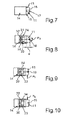
- Fig. 7 is in a page representation the execution according to Fig. 3 shown. It can be seen that the control element 11 projects beyond the front side 13 of the control panel 9 to the front and thus also protrudes from the receptacle 14 and the opening 15 to the front.
- control element 11 can not only be rotated about the arc path 24, but also starting from the illustration in FIG Fig. 7 can be tilted up and down.
- maximum tilt angles preferably, with respect to the horizontal, maximum tilt angles of less than 10 °, in particular less than 5 °, preferably 3 °, are provided upwards and downwards.
- Fig. 8 is a sectional view taken along section line VIII-VIII in Fig. 3 shown here, in which case the operating element 11 is shown again in the unactuated basic position or starting position.
- the mentioned movements are indicated upwards and downwards.
- the distance d over which the operating element 11 extends to the front extends over the opening 15 and also the front side 13 to the outside. This is a maximum of 1 cm, less than or equal to 0.5 cm.
- the operating element 11 engages on its rear side in guide slots 30 and 31 and correspondingly, for the sake of clarity serving unspecified marked guide pins are provided.
- the operating element 11 can then be tilted via a pivot point 32 upwards or downwards.
- the control element 11 with electrical contacts spaced to switching elements 33 and 34 are arranged so that no switching signals are generated in this basic position.
- Fig. 9 a corresponding longitudinal sectional view in Fig. 3 shown attached to the same place as the sectional view VIII-VIII.
- a tilting upward along the arrow P5 starting from the in Fig. 8 shown basic position performed.
- the operating element 11 is contacted with the formed on a wall in the receptacle 14 switching element 33 and generates a corresponding switching signal.
- FIGS. 8 and 9 a further operating state of the operating element 11 is shown, in which case starting from the Presentation in Fig. 8 an actuation or tilting down along the arrow P6 is performed.
- the tilted down end position is then shown, wherein electrical contacts on the operating element 11 are then electrically contacted with the upper switching element 34.
- corresponding operating condition settings can then be made, in which case, for example, a selection of functional subunits or setting of operating parameters, for example the duration of an operation of a selected functional subunit, can also be set.
Landscapes
- Engineering & Computer Science (AREA)
- Physics & Mathematics (AREA)
- General Physics & Mathematics (AREA)
- Automation & Control Theory (AREA)
- Chemical & Material Sciences (AREA)
- Combustion & Propulsion (AREA)
- Mechanical Engineering (AREA)
- General Engineering & Computer Science (AREA)
- Electric Ovens (AREA)
- Switches With Compound Operations (AREA)
Applications Claiming Priority (1)
| Application Number | Priority Date | Filing Date | Title |
|---|---|---|---|
| DE102010043847A DE102010043847A1 (de) | 2010-11-12 | 2010-11-12 | Bedienvorrichtung für ein Hausgerät sowie Hausgerät, insbesondere zum Zubereiten von Lebensmitteln mit einer Bedienvorrichtung |
Publications (2)
| Publication Number | Publication Date |
|---|---|
| EP2455667A2 true EP2455667A2 (fr) | 2012-05-23 |
| EP2455667A3 EP2455667A3 (fr) | 2017-11-15 |
Family
ID=45218219
Family Applications (1)
| Application Number | Title | Priority Date | Filing Date |
|---|---|---|---|
| EP11187440.0A Withdrawn EP2455667A3 (fr) | 2010-11-12 | 2011-11-02 | Dispositif de commande pour un appareil ménager et appareil ménager, notamment pour la préparation d'aliments, doté d'un dispositif de commande |
Country Status (2)
| Country | Link |
|---|---|
| EP (1) | EP2455667A3 (fr) |
| DE (1) | DE102010043847A1 (fr) |
Family Cites Families (9)
| Publication number | Priority date | Publication date | Assignee | Title |
|---|---|---|---|---|
| US3007465A (en) * | 1959-04-20 | 1961-11-07 | Cribben And Sexton Company | Surface cooking unit |
| GB1568705A (en) * | 1977-07-18 | 1980-06-04 | Belling & Co Ltd | Control panels for cooking appliances |
| DE4216678A1 (de) * | 1992-05-20 | 1993-11-25 | Bosch Siemens Hausgeraete | Kochmulde |
| JP2001273093A (ja) * | 2000-03-23 | 2001-10-05 | Aiwa Co Ltd | 操作部機構 |
| JP4087603B2 (ja) * | 2001-12-25 | 2008-05-21 | アルプス電気株式会社 | スライド型電気部品 |
| JP2005108570A (ja) * | 2003-09-29 | 2005-04-21 | Mitsumi Electric Co Ltd | 複合操作型スイッチ装置 |
| JP4561602B2 (ja) * | 2005-11-14 | 2010-10-13 | 住友電装株式会社 | 回転操作装置 |
| JP2008047367A (ja) * | 2006-08-11 | 2008-02-28 | Teikoku Tsushin Kogyo Co Ltd | 複合型電子部品用のケース及びその製造方法及び複合型電子部品 |
| DE102007035894A1 (de) * | 2007-07-31 | 2009-02-05 | BSH Bosch und Siemens Hausgeräte GmbH | Haushaltsgerätebedienvorrichtung |
-
2010
- 2010-11-12 DE DE102010043847A patent/DE102010043847A1/de not_active Withdrawn
-
2011
- 2011-11-02 EP EP11187440.0A patent/EP2455667A3/fr not_active Withdrawn
Non-Patent Citations (1)
| Title |
|---|
| None |
Also Published As
| Publication number | Publication date |
|---|---|
| EP2455667A3 (fr) | 2017-11-15 |
| DE102010043847A1 (de) | 2012-05-16 |
Similar Documents
| Publication | Publication Date | Title |
|---|---|---|
| EP2652406B1 (fr) | Dispositif de commande pour appareil ménager doté d'un afficheur électronique et appareil ménager doté d'un dispositif de commande de ce type | |
| DE102007008897A1 (de) | Versenkbares Bedienelement für ein Hausgerät und Hausgerät, insbesondere Backofen | |
| DE102008041519B4 (de) | Türgriff für eine Tür eines Hausgeräts und Tür für ein Hausgerät | |
| EP3183500A1 (fr) | Dispositif de commande d'un appareil ménager comportant une partie avant d'élément de commande positionnée de manière stable | |
| EP3183499A1 (fr) | Dispositif de commande d'un appareil ménager muni d'un élément de commande et d'une zone d'affichage réalisée dans l'élément de commande | |
| DE10355603A1 (de) | Schaltvorrichtung und Anordnung zur Erfassung unterschiedlicher Positionen eines Türelements | |
| EP2063188A2 (fr) | Appareil de cuisson doté d'une adaptation d'éclairage automatique | |
| DE102004046129A1 (de) | Griffstange für ein Haushaltsgerät, insbesondere Herd oder Backofen | |
| EP2455668A2 (fr) | Dispositif de commande pour un appareil ménager et appareil ménager, notamment pour la préparation d'aliments, doté d'un dispositif de commande | |
| DE102006049396A1 (de) | Haushaltsgerät mit Projektionsanzeige | |
| WO2021160396A1 (fr) | Dispositif de commande d'opérateur comprenant un élément de commande d'opérateur à composants multiples, et appareil ménager et procédé de fonctionnement d'un appareil ménager | |
| EP2652403B1 (fr) | Appareil ménager comprenant un dispositif de commande | |
| EP1449300A2 (fr) | Appareil electromenager | |
| EP2993959B1 (fr) | Appareil ménager | |
| EP1470369B1 (fr) | Four de cuisson | |
| EP2455667A2 (fr) | Dispositif de commande pour un appareil ménager et appareil ménager, notamment pour la préparation d'aliments, doté d'un dispositif de commande | |
| WO2010112463A1 (fr) | Dispositif de commande pour appareil électroménager, appareil électroménager équipé d'un tel dispositif de commande, et procédé permettant de faire fonctionner un appareil électroménager équipé d'un tel dispositif de commande | |
| EP3338025A1 (fr) | Dispositif de commande pour un appareil ménager comprenant un guide de lumière servant à l'éclairage de plusieurs zones d'un capot avant à des intensités de lumière différentes, appareil ménager comprenant un dispositif de commande de ce type, et procédé servant à faire fonctionner un dispositif de commande | |
| DE102011078595A1 (de) | Bedienvorrichtung für ein Hausgerät sowie Hausgerät, insbesondere zum Zubereiten von Lebensmitteln mit einer Bedienvorrichtung | |
| DE102009047683A1 (de) | Bedienvorrichtung für ein Hausgerät sowie Hausgerät mit einer derartigen Bedienvorrichtung | |
| DE102011078594A1 (de) | Bedienvorrichtung für ein Hausgerät sowie Hausgerät, insbesondere zum Zubereiten von Lebensmitteln mit einer Bedienvorrichtung | |
| DE102011078596A1 (de) | Bedienvorrichtung für ein Hausgerät sowie Hausgerät, insbesondere zum Zubereiten von Lebensmitteln mit einer Bedienvorrichtung | |
| DE19722044A1 (de) | Gargerät, insbesondere Backofen | |
| EP2383521B1 (fr) | Boîtier pour une hotte aspirante | |
| DE10008015A1 (de) | Haushaltsgerät mit einer Zeitschaltereinrichtung |
Legal Events
| Date | Code | Title | Description |
|---|---|---|---|
| PUAI | Public reference made under article 153(3) epc to a published international application that has entered the european phase |
Free format text: ORIGINAL CODE: 0009012 |
|
| AK | Designated contracting states |
Kind code of ref document: A2 Designated state(s): AL AT BE BG CH CY CZ DE DK EE ES FI FR GB GR HR HU IE IS IT LI LT LU LV MC MK MT NL NO PL PT RO RS SE SI SK SM TR |
|
| AX | Request for extension of the european patent |
Extension state: BA ME |
|
| RAP1 | Party data changed (applicant data changed or rights of an application transferred) |
Owner name: BSH HAUSGERAETE GMBH |
|
| PUAL | Search report despatched |
Free format text: ORIGINAL CODE: 0009013 |
|
| AK | Designated contracting states |
Kind code of ref document: A3 Designated state(s): AL AT BE BG CH CY CZ DE DK EE ES FI FR GB GR HR HU IE IS IT LI LT LU LV MC MK MT NL NO PL PT RO RS SE SI SK SM TR |
|
| AX | Request for extension of the european patent |
Extension state: BA ME |
|
| RIC1 | Information provided on ipc code assigned before grant |
Ipc: F24C 7/08 20060101ALI20171012BHEP Ipc: G05G 5/05 20060101ALI20171012BHEP Ipc: G05G 9/047 20060101ALI20171012BHEP Ipc: H01H 25/00 20060101AFI20171012BHEP Ipc: D06F 39/00 20060101ALI20171012BHEP Ipc: G01G 1/04 20060101ALI20171012BHEP Ipc: A47L 15/42 20060101ALI20171012BHEP Ipc: H01H 21/24 20060101ALI20171012BHEP Ipc: H01H 21/02 20060101ALI20171012BHEP |
|
| STAA | Information on the status of an ep patent application or granted ep patent |
Free format text: STATUS: THE APPLICATION IS DEEMED TO BE WITHDRAWN |
|
| 18D | Application deemed to be withdrawn |
Effective date: 20180516 |