EP2455683A2 - Fixation d'éléments en forme de plaques - Google Patents
Fixation d'éléments en forme de plaques Download PDFInfo
- Publication number
- EP2455683A2 EP2455683A2 EP11009126A EP11009126A EP2455683A2 EP 2455683 A2 EP2455683 A2 EP 2455683A2 EP 11009126 A EP11009126 A EP 11009126A EP 11009126 A EP11009126 A EP 11009126A EP 2455683 A2 EP2455683 A2 EP 2455683A2
- Authority
- EP
- European Patent Office
- Prior art keywords
- module
- rail
- fastening
- elements
- mounting system
- Prior art date
- Legal status (The legal status is an assumption and is not a legal conclusion. Google has not performed a legal analysis and makes no representation as to the accuracy of the status listed.)
- Withdrawn
Links
Images


Classifications
-
- H—ELECTRICITY
- H02—GENERATION; CONVERSION OR DISTRIBUTION OF ELECTRIC POWER
- H02S—GENERATION OF ELECTRIC POWER BY CONVERSION OF INFRARED RADIATION, VISIBLE LIGHT OR ULTRAVIOLET LIGHT, e.g. USING PHOTOVOLTAIC [PV] MODULES
- H02S20/00—Supporting structures for PV modules
- H02S20/20—Supporting structures directly fixed to an immovable object
- H02S20/22—Supporting structures directly fixed to an immovable object specially adapted for buildings
- H02S20/23—Supporting structures directly fixed to an immovable object specially adapted for buildings specially adapted for roof structures
- H02S20/25—Roof tile elements
-
- F—MECHANICAL ENGINEERING; LIGHTING; HEATING; WEAPONS; BLASTING
- F24—HEATING; RANGES; VENTILATING
- F24S—SOLAR HEAT COLLECTORS; SOLAR HEAT SYSTEMS
- F24S25/00—Arrangement of stationary mountings or supports for solar heat collector modules
- F24S25/10—Arrangement of stationary mountings or supports for solar heat collector modules extending in directions away from a supporting surface
- F24S25/12—Arrangement of stationary mountings or supports for solar heat collector modules extending in directions away from a supporting surface using posts in combination with upper profiles
-
- F—MECHANICAL ENGINEERING; LIGHTING; HEATING; WEAPONS; BLASTING
- F24—HEATING; RANGES; VENTILATING
- F24S—SOLAR HEAT COLLECTORS; SOLAR HEAT SYSTEMS
- F24S25/00—Arrangement of stationary mountings or supports for solar heat collector modules
- F24S25/60—Fixation means, e.g. fasteners, specially adapted for supporting solar heat collector modules
- F24S25/63—Fixation means, e.g. fasteners, specially adapted for supporting solar heat collector modules for fixing modules or their peripheral frames to supporting elements
- F24S25/632—Side connectors; Base connectors
-
- F—MECHANICAL ENGINEERING; LIGHTING; HEATING; WEAPONS; BLASTING
- F24—HEATING; RANGES; VENTILATING
- F24S—SOLAR HEAT COLLECTORS; SOLAR HEAT SYSTEMS
- F24S25/00—Arrangement of stationary mountings or supports for solar heat collector modules
- F24S25/60—Fixation means, e.g. fasteners, specially adapted for supporting solar heat collector modules
- F24S25/63—Fixation means, e.g. fasteners, specially adapted for supporting solar heat collector modules for fixing modules or their peripheral frames to supporting elements
- F24S25/634—Clamps; Clips
-
- H—ELECTRICITY
- H02—GENERATION; CONVERSION OR DISTRIBUTION OF ELECTRIC POWER
- H02S—GENERATION OF ELECTRIC POWER BY CONVERSION OF INFRARED RADIATION, VISIBLE LIGHT OR ULTRAVIOLET LIGHT, e.g. USING PHOTOVOLTAIC [PV] MODULES
- H02S20/00—Supporting structures for PV modules
- H02S20/20—Supporting structures directly fixed to an immovable object
- H02S20/22—Supporting structures directly fixed to an immovable object specially adapted for buildings
- H02S20/23—Supporting structures directly fixed to an immovable object specially adapted for buildings specially adapted for roof structures
- H02S20/24—Supporting structures directly fixed to an immovable object specially adapted for buildings specially adapted for roof structures specially adapted for flat roofs
-
- E—FIXED CONSTRUCTIONS
- E04—BUILDING
- E04F—FINISHING WORK ON BUILDINGS, e.g. STAIRS, FLOORS
- E04F13/00—Coverings or linings, e.g. for walls or ceilings
- E04F13/07—Coverings or linings, e.g. for walls or ceilings composed of covering or lining elements; Sub-structures therefor; Fastening means therefor
- E04F13/08—Coverings or linings, e.g. for walls or ceilings composed of covering or lining elements; Sub-structures therefor; Fastening means therefor composed of a plurality of similar covering or lining elements
- E04F13/0801—Separate fastening elements
- E04F13/0803—Separate fastening elements with load-supporting elongated furring elements between wall and covering elements
- E04F13/081—Separate fastening elements with load-supporting elongated furring elements between wall and covering elements with additional fastening elements between furring elements and covering elements
- E04F13/083—Hooking means on the back side of the covering elements
-
- F—MECHANICAL ENGINEERING; LIGHTING; HEATING; WEAPONS; BLASTING
- F24—HEATING; RANGES; VENTILATING
- F24S—SOLAR HEAT COLLECTORS; SOLAR HEAT SYSTEMS
- F24S25/00—Arrangement of stationary mountings or supports for solar heat collector modules
- F24S2025/01—Special support components; Methods of use
- F24S2025/015—Supports with play between elements
-
- F—MECHANICAL ENGINEERING; LIGHTING; HEATING; WEAPONS; BLASTING
- F24—HEATING; RANGES; VENTILATING
- F24S—SOLAR HEAT COLLECTORS; SOLAR HEAT SYSTEMS
- F24S25/00—Arrangement of stationary mountings or supports for solar heat collector modules
- F24S2025/01—Special support components; Methods of use
- F24S2025/016—Filling or spacing means; Elastic means
-
- F—MECHANICAL ENGINEERING; LIGHTING; HEATING; WEAPONS; BLASTING
- F24—HEATING; RANGES; VENTILATING
- F24S—SOLAR HEAT COLLECTORS; SOLAR HEAT SYSTEMS
- F24S25/00—Arrangement of stationary mountings or supports for solar heat collector modules
- F24S2025/01—Special support components; Methods of use
- F24S2025/018—Means for preventing movements, e.g. stops
-
- F—MECHANICAL ENGINEERING; LIGHTING; HEATING; WEAPONS; BLASTING
- F24—HEATING; RANGES; VENTILATING
- F24S—SOLAR HEAT COLLECTORS; SOLAR HEAT SYSTEMS
- F24S25/00—Arrangement of stationary mountings or supports for solar heat collector modules
- F24S25/60—Fixation means, e.g. fasteners, specially adapted for supporting solar heat collector modules
- F24S2025/601—Fixation means, e.g. fasteners, specially adapted for supporting solar heat collector modules by bonding, e.g. by using adhesives
-
- F—MECHANICAL ENGINEERING; LIGHTING; HEATING; WEAPONS; BLASTING
- F24—HEATING; RANGES; VENTILATING
- F24S—SOLAR HEAT COLLECTORS; SOLAR HEAT SYSTEMS
- F24S25/00—Arrangement of stationary mountings or supports for solar heat collector modules
- F24S2025/80—Special profiles
- F24S2025/804—U-, C- or O-shaped; Hat profiles
-
- Y—GENERAL TAGGING OF NEW TECHNOLOGICAL DEVELOPMENTS; GENERAL TAGGING OF CROSS-SECTIONAL TECHNOLOGIES SPANNING OVER SEVERAL SECTIONS OF THE IPC; TECHNICAL SUBJECTS COVERED BY FORMER USPC CROSS-REFERENCE ART COLLECTIONS [XRACs] AND DIGESTS
- Y02—TECHNOLOGIES OR APPLICATIONS FOR MITIGATION OR ADAPTATION AGAINST CLIMATE CHANGE
- Y02B—CLIMATE CHANGE MITIGATION TECHNOLOGIES RELATED TO BUILDINGS, e.g. HOUSING, HOUSE APPLIANCES OR RELATED END-USER APPLICATIONS
- Y02B10/00—Integration of renewable energy sources in buildings
- Y02B10/10—Photovoltaic [PV]
-
- Y—GENERAL TAGGING OF NEW TECHNOLOGICAL DEVELOPMENTS; GENERAL TAGGING OF CROSS-SECTIONAL TECHNOLOGIES SPANNING OVER SEVERAL SECTIONS OF THE IPC; TECHNICAL SUBJECTS COVERED BY FORMER USPC CROSS-REFERENCE ART COLLECTIONS [XRACs] AND DIGESTS
- Y02—TECHNOLOGIES OR APPLICATIONS FOR MITIGATION OR ADAPTATION AGAINST CLIMATE CHANGE
- Y02B—CLIMATE CHANGE MITIGATION TECHNOLOGIES RELATED TO BUILDINGS, e.g. HOUSING, HOUSE APPLIANCES OR RELATED END-USER APPLICATIONS
- Y02B10/00—Integration of renewable energy sources in buildings
- Y02B10/20—Solar thermal
-
- Y—GENERAL TAGGING OF NEW TECHNOLOGICAL DEVELOPMENTS; GENERAL TAGGING OF CROSS-SECTIONAL TECHNOLOGIES SPANNING OVER SEVERAL SECTIONS OF THE IPC; TECHNICAL SUBJECTS COVERED BY FORMER USPC CROSS-REFERENCE ART COLLECTIONS [XRACs] AND DIGESTS
- Y02—TECHNOLOGIES OR APPLICATIONS FOR MITIGATION OR ADAPTATION AGAINST CLIMATE CHANGE
- Y02E—REDUCTION OF GREENHOUSE GAS [GHG] EMISSIONS, RELATED TO ENERGY GENERATION, TRANSMISSION OR DISTRIBUTION
- Y02E10/00—Energy generation through renewable energy sources
- Y02E10/40—Solar thermal energy, e.g. solar towers
- Y02E10/47—Mountings or tracking
-
- Y—GENERAL TAGGING OF NEW TECHNOLOGICAL DEVELOPMENTS; GENERAL TAGGING OF CROSS-SECTIONAL TECHNOLOGIES SPANNING OVER SEVERAL SECTIONS OF THE IPC; TECHNICAL SUBJECTS COVERED BY FORMER USPC CROSS-REFERENCE ART COLLECTIONS [XRACs] AND DIGESTS
- Y02—TECHNOLOGIES OR APPLICATIONS FOR MITIGATION OR ADAPTATION AGAINST CLIMATE CHANGE
- Y02E—REDUCTION OF GREENHOUSE GAS [GHG] EMISSIONS, RELATED TO ENERGY GENERATION, TRANSMISSION OR DISTRIBUTION
- Y02E10/00—Energy generation through renewable energy sources
- Y02E10/50—Photovoltaic [PV] energy
Definitions
- the invention relates to a mounting system for plate-shaped elements in general and for facade elements, thermal generator elements, solar thermal collectors, photovoltaic modules or solar modules in particular, for attaching such an element to at least one upper and one lower transverse rail parallel and spaced from each other are arranged for holding such a plate-shaped element. Furthermore, the invention relates to a plate-shaped element with such a mounting system and a substructure for holding such an element.
- PV photovoltaic
- DE 10 2008 052 594 A1 shows a multi-part holding system for fixing plate-shaped solar modules at four edge points by means of a holder of a clamping device.
- the clamping device comprises an upper U-shaped holder with a mouth-shaped opening for an upper module and a U-shaped holder with a mouth-shaped opening for a lower module, wherein these holders are arranged one above the other and the openings are oriented away from one another.
- the clamping device is mounted by means of a fastening portion via a central screw on the building, wherein the upper bracket and / or the lower bracket with respect to this mounting portion can be pivoted and locked or is.
- the disadvantage here is that the holding system consists of numerous mounting parts and therefore the installation requires a lot of time. Furthermore, in The modules experience critical stresses due to clamping at four points under load.
- DE 10 2009 024 615 A1 shows a mounting system for PV modules with at least two profile-shaped cross rails, which are arranged in parallel spaced and provided for holding a plurality of PV modules and each having a planar support surface. With the back of a PV module holders are firmly connected by means of an adhesive, wherein the PV module can be suspended by means of the holder on the cross rails.
- each cross rail is associated with at least one holder, each holder having a recess and each cross rail has an integrated projection or vice versa.
- the PV module is first placed for hanging on the cross rails so that the holder flat on the support surfaces of the cross rails, and then there resting in a joining direction perpendicular to the cross rails, the recesses and the projections engage with each other. Between at least one cross rail and an associated holder a retaining device is provided which prevents displacement of the holder against the joining direction.
- the disadvantage here is that the holder for realizing a tolerance compensation with respect to the spacing of the cross rails as well as to secure the PV module against theft or wind suction is very complex.
- the mounting structure has a base with two receiving profiles, which cooperate with retaining profiles for mounting the solar module.
- the receiving and holding profiles form a lock.
- the module carrier has front and rear retaining profiles with holders for the profiles as well as a wind seal element.
- FR 2 928 672 A1 From the FR 2 928 672 A1 is a facade cladding, especially for a facade or a roof known.
- plate-shaped means that such an element has a significantly smaller thickness compared to its length and width, ie has substantially the shape of a plate.
- the outer contour of the plate-shaped elements is usually rectangular or square, but may basically have any desired shape.
- the mounting system has at least one fastening element which is firmly connected to a rear side of the plate-shaped element and which has at least one anchoring means arranged on and preferably substantially perpendicular to the plane of the back for attachment to the upper transverse rail.
- the fastening element is arranged with respect to a fall line in the installed position of the element to an upper edge of an outer contour of the element at a smaller distance than to a lower edge of the outer contour.
- the lower bearing point of the element is secured against the support direction.
- About the dimensioning of the mouth width of the mouth-shaped opening can be secured with an interposed elastic material - the element better against unauthorized decrease and especially against wind buoyancy and concomitant fluttering of the element.
- the attachment points at the upper bearing points, i. the bivalent bearings protected against moment load on the element.
- the elastic element can be made in cross section e.g. be triangular, oval, circular or square be formed.
- the plane of the cross section runs transversely, in particular at right angles, to the surface plane of the plate-shaped elements.
- the plane of the cross section can run in such a way that the fall line falls in this cross-sectional plane. This makes it possible to produce the elastic element by cutting to length of existing material strands.
- the elastic member may be made of a soft rubber, silicone or ethylene-propylene-diene rubber (EPDM).
- Soft rubber is a particularly inexpensive and easy-to-use material.
- Silicone or ethylene-propylene-diene rubber (EPDM) are particularly suitable since both materials are particularly UV resistant.
- silicone or ethylene-propylene-diene rubber (EPDM) are particularly resistant to chemicals, in particular to ammonia-containing gases, such as may occur in the vicinity of utility buildings for livestock farming in increased concentrations.
- the elastic element can be fastened to the PV module or a substructure by a material fit. If the elastic element is made of silicone, can The silicone is sprayed onto the PV module and brought into its desired shape. However, it is also possible to use a prefabricated elastic element, for example of ethylene-propylene-diene rubber (EPDM), for the production of this integral connection which is adhesively bonded to a PV module.
- EPDM ethylene-propylene-diene rubber
- the essence of the invention is the realization of a particularly simple attachment of the plate-shaped element with a bivalent bearing, in the form of a bearing with an anchoring means, which is determined for example by positive engagement or possibly also an adhesive in a matching receptacle.
- the attachment of the entire element to the substructure is primarily with the anchoring means and can therefore be very simple, fast and still secure.
- the mounting system further at least one securing element is provided, which is arranged with respect to the fall line in the installation position of the element below the fastener.
- the securing element is designed so that it restricts in the installation position of the element, the freedom of movement of the element perpendicular to the mounting plane away from the substructure or completely prevented with appropriate dimensioning.
- the core idea of the advantageous development is to realize the attachment of the plate-shaped element by a combination of a monovalent bearing, in the form of a simple Auflagerung, with the bivalent bearing, in the form of Auflagerung with the anchoring means.
- the attachment of the entire element to the substructure continues to be primarily with the anchoring means and can therefore be very simple, fast and still secure.
- stresses in the element for example a glass plate or silicon layer of the element, are minimized or prevented on account of mechanical and / or thermal stresses.
- the securing element can have an angled arm which is spaced apart and parallel to the rear side of the element and substantially perpendicular to the falling line.
- the arm essentially forms with the back in the direction of the fall line open mouth-shaped opening for engaging behind an undercut formed from the view of the mounting plane on or from the lower cross rail.
- the type of adhesive suitable for the adhesive bond is essentially determined by the materials to be bonded. If the fastening elements and, if appropriate, securing elements are made of a metal, then, for example, a silicone-based adhesive is particularly suitable for bonding to the glass rear side of a PV module as a plate-shaped element. Such a PV module could be laminated on the back, for example for improved protection of the glass carrier with a plastic layer. In this case, if the fasteners and possibly securing elements also made of a plastic, a cohesive attachment, such. B. by ultrasonic welding or friction welding, are used for attachment. Alternatively, it is also always possible to use a carrier coated on both sides with a suitable adhesive in the manner of a double-sided adhesive tape.
- a plurality of fastening elements and possibly a plurality of securing elements can be arranged on the rear side of the element on a line extending substantially perpendicular to the falling line.
- a fastening element and a securing elements are arranged on the back of the element on a substantially parallel to the fall line line. It should be noted, however, that a lateral offset between a fastener and a securing elements arranged underneath does not affect the function of the fastening system.
- the fastening element and / or the securing element can also be embodied as a profiled rail, which is or are attached to the rear side of the element substantially perpendicular to the falling line.
- the anchoring element and the angled arm of the securing element can then also be designed corresponding web-shaped and cooperate with the respective cross rails as intended.
- the at least one fastening element or the at least one elastic element can each be arranged at a distance from the outer contour of the element in the area inside of the rear side.
- the attachment points of the fasteners and the bearing points of the element on the lower cross rail can be chosen so that the for the element in the installed position Locate resulting support points in such places that the element undergoes a minimal bending load in the installed position.
- the attachment points can be selected at the back of the element so that when an elastic deformation of the element by surface loading z. B. result due to wind or snow in the attachment points for the bending load horizontal tangent. Then no torque is applied to the attachment points.
- the anchoring means of the fastening element can be embodied as an anchor body, for example in the form of a pin, with a displaceable and automatically resetting undercut element arranged at an end of the anchor body opposite the rear side of the element.
- the undercut element may for example be designed in the form of at least one snap-locking element or as Schapphaken.
- the material of the anchoring element can be so elastic that it can expand after overcoming a bottleneck in a receptacle on the cross rail again and so can engage behind the undercut.
- the invention also relates to plate-shaped elements, in particular plate-shaped facade elements, thermal generator elements, thermal solar panels, photovoltaic modules or solar modules, which have a back to which a mounting system according to the invention is attached.
- the invention further relates to a substructure for forming a mounting plane and for holding at least one plate-shaped element, on the back of a mounting system according to the invention is mounted in the mounting plane.
- At least the second transverse rail, at least in the region of lower support points from the perspective of the mounting plane on an undercut for a fastened to the element fuse element.
- an elastic element preferably of a silicone rubber
- an elastic buffer element can also be fastened by means of an adhesive connection.
- such an element in particular when the first and second transverse rails are substantially identical, can also be anchored in a form-fitting manner to the recesses, which in the case of use are provided as the first transverse rail for connection to a fastening element.
- At least the first transverse rail can be designed as a profile rail, in particular with a C-profile, with a groove in the support plane.
- the groove then forms the recess for the fastening element and has at least the undercut for the displaceable undercut element.
- At least the second transverse rail can have a cantilever extending along the transverse rail and parallel to the mounting plane for forming the undercut for a securing element from the perspective of the mounting plane.
- the profile of the cross rail may also be designed to be symmetrical in order to avoid incorrect assembly, i. on both sides from the perspective of the mounting plane have the cantilever.
- the undercut can also be formed from the view of the mounting plane through the rear side of the second transverse rail. It is understood that the securing element must be adapted only in the mouth width of the type or shape of the undercut.
- Fig. 1 and Fig. 2 schematically show the fastening and securing system or mounting system according to the invention with reference to a PV module array with a plurality of arranged on a substructure or support structure plate-shaped PV modules as an example of plate-shaped elements in the context of the invention.
- the PV module field in the application example consists of nine identical plate-shaped solar modules or PV modules 1.
- the PV modules may be, for example, frameless plate-shaped thin-film modules with a rectangular format.
- the fastening system according to the invention is basically also suitable for other types of plate-shaped elements, such as the already mentioned facade elements, thermal generator elements, solar thermal collectors and the like.
- the PV modules 1 are arranged obliquely on the substructure in an angle ⁇ that is usually optimized in terms of the angle of incidence of the sun at the installation site.
- the substructure includes this two long columns 2 and two short Supports 3 and two inclined beams 4, wherein each one of the oblique beams 4 are arranged by means of one of the long columns 2 and one of the short supports 3 obliquely at an angle ⁇ relative to a horizontal or horizontal plane 5.
- the two inclined beams 4 form arranged thereon transverse rails 60 a mounting plane 7, which is also inclined at an angle ⁇ of, for example, about 30 ° relative to the horizontal plane 5.
- the mounting plane 7 is parallel to a module plane defined by the plate-shaped PV modules 1.
- a PV module 1 is thus also arranged in the mounting plane or module level on the substructure with respect to the horizontal plane 5 at an angle ⁇ .
- the PV modules 1 can be arranged even at a certain angle to the mounting plane 7 on the substructure or be.
- the arrow 10 in the Fig. 1 to 3 illustrates the downslope direction of the PV modules 1.
- the fall line for the plate-shaped modules here is a line on the surface that follows the direction of the greatest gradient, ie the fall line would always intersect at the module applied contour lines at right angles.
- the cross rails 60 have in the illustrated embodiment, a cross section in the form of a so-called C-profile, wherein the cross section over the entire length is uniform.
- the profile of the cross rails 60 is in Fig. 4a shown more clearly.
- transverse rails 60 of the substructure on a building envelope, in particular on a facade or a roof of the building. If the PV modules are installed on a pitched roof, it may also be sufficient, if the roof pitch is suitable, to install the required crossbars directly on the roof, if necessary, using spacers. Essential for the still to be explained function of the mounting system is that the cross rails 60 as shown to the fall line 10 of the PV modules 1 are substantially transverse.
- Fig. 1 and 2 show further that each plate-shaped PV module 1 is mounted at at least four points or locations on each of the two transverse rails 60, wherein each of the two transverse rails 60 each two of the support points as upper support points 8a and 8b as lower support points.
- the support points 8a, 8b are shown for the sake of simplicity only in connection with the PV module 1a. All bearing points 8a, 8b absorb the normal forces emanating from the PV module, which can be caused by the weight force and possibly additional loads such as wind or snow.
- the upper bearing points 8a additionally take on the direction of the fall line 10 directed component of these forces.
- the fastening elements 20 or securing elements 30a, 30b can already be factory-mounted on the rear side of the PV modules 1 in an industrial manufacturing process.
- the fastening elements 20 or securing elements 30a, 30b are fixedly connected to the fastening surface 13 by means of the adhesive layer 12 with the planar rear side 11 1 of the PV module 1.
- the adhesive layer 12 is for example in the Fig. 4a and 4b schematically recognizable between the back 11 of the PV module 1 and the fastener 20 and the fuse element 30.
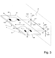
- Fig. 3 shows a perspective view of the PV module 1a with four schematically indicated on the back 11 mounting surfaces 13a of the fasteners 20 and mounting surfaces 13b of the fuse elements 30a and 30b. Furthermore, the upper support points 8a and the lower support points 8b are indicated. To illustrate the bearing forces or safety bearing forces occurring in the event of a fall, corresponding force arrows are shown in the projection plane P indicated to the right of the PV module 1.
- the illustration in the projection plane P shows that, for the three-dimensional load case of the plate-shaped PV module 1 with regard to the function of the fastening according to the invention, the interplay of a respective upper support point 8a with a lower support point 8b is important.
- the function of the attachment and mounting of the PV module 1 according to the invention is reduced to a two-dimensional representation and thus corresponds substantially to the side views of Fig. 4a and 4b ,
- the bearing forces LK1, LK2, LK3 occurring in the support points L1 and L2 are shown.
- the bearing forces LK2, LK3 correspond to the perpendicular forces introduced into the support points of the PV module 1a.
- the bearing force LK2 corresponds to the proportion of the weight force and forces acting on the PV module, which acts in the direction of the fall line 10. This bearing force LK1 is in the upper attachment point of even closer in connection with the Fig. 4a to be explained anchoring means of the fastener 20.
- securing forces SK1 to SK4 are applied, which are shown with a distance to the respective projection point in the projection plane.
- the distance illustrates a predetermined clearance on the fastener 20 and on the fuse element 30a, i. the PV module 1a can be moved by a certain distance in the direction of the respective arrow of the securing forces, before forces must respectively be taken up by the fastening element 20 or securing element 30a.
- the bearing clearance can be influenced, for example with regard to the force SK3, by appropriate dimensioning of the jaw width of the securing element 30a. Only with regard to the forces SK2 and SK4 should a sufficient overall clearance be ensured in order to allow the PV module enough "freedom of movement" so that temperature fluctuations can not cause thermal stresses in the PV module.
- Intermediate elements suitable for this purpose could be produced, for example, from an elastic material such as a silicone-based elastomer (eg silicone rubber) or even soft plastic, for example by direct injection onto the corresponding points of the fastening elements 20 or securing elements 30a, 30b.
- an elastic material such as a silicone-based elastomer (eg silicone rubber) or even soft plastic, for example by direct injection onto the corresponding points of the fastening elements 20 or securing elements 30a, 30b.
- the projection point P1 illustrates the forces associated with the fastener 20 connected to the back surface 11 of the PV module 1a at the attachment surfaces 13a. In installation position, the forces are from the fastener LK1 and LK2 removed in an upper cross rail of the substructure.
- the projection point P2 illustrates the force LK3 removed at the lower support point 8b in the installation position of the PV module 1a in the lower transverse rail of the substructure.
- the projection point P3 illustrates the delay element of a fuse element 30a connected to the back face 11 of the PV module 1a at the attachment surface 13b. That is, if the PV module 1a is raised, for example, by wind lift, then the fuse element captures the PV module 1a only after a certain distance and then transmits the applied forces in the below cross rail. As already discussed, by appropriate dimensioning of the backup game, for example by interposing an elastic element, damage to the PV module 1a by flutter due to wind lift can be completely avoided.
- FIG. 4a is a side view of the PV module 1a of Fig. 1, 2 and 3 , It can be seen that a fastening element 20 is attached by means of the adhesive layer 12 to the plate-shaped base body of the PV module 1a on its rear side 11 at the attachment point 13a.
- anchoring means with a Anchor body 23.
- the anchor body 23 is designed so that it can be brought into engagement with a groove 61 in an upper cross rail 60a of the transverse rails 60 of a substructure.
- the upper transverse rail 60a has a C-profile for this purpose with a groove 61.
- the groove 61 has a substantially U-shaped basic shape with inwardly directed undercuts 62a and 62b at the two leg ends of the U-shape, i. at the opening of the groove 61.
- Essential for the function of the fastener 20 is the presence of at least one of the undercuts 62a and 62b on the U-legs.
- the bottom 63 of the groove 61 could basically in the cross rail 60 down and partially open so broken, for example, be designed as a drain for condensation.
- the anchoring means has two snap hooks 24, which when inserting the anchor body 23 in the groove 61 avoid the undercuts 62a, 62b or be deflected or compressed at the bottleneck formed by the undercuts 62a, 62b and inside the groove 61 after passage of the Again spread or pinch bottleneck and so the undercuts 62 a, 62 b engage behind.
- Fig. 4b is provided on the groove in the cross rail 60a only one undercut 62b and therefore also formed on the anchor body 23, only one snap hook 24 for engaging behind the undercut 62b.
- the anchoring means can basically be designed as a latching connection or anchor or the like.
- the anchoring means could also consist of a mushroom-shaped elastic and thus compressible material which is compressed when inserted into the groove 61 and then expands inside the groove 61 again to engage behind the undercuts 62a, 62b in this way.
- the fastening element 20 forms a form-locking connection in the manner of a snap-lock connection, which thus can be easily manufactured and depending on the dimensions only destructive or only with high power, if necessary, can be solved with a special tool again.
- the positive connection can be designed as an effective protection against theft by an attempt to remove the PV module 1 a of the cross rails leads to the destruction of the PV module.
- the anchoring means prefferably be permanently glued into the groove-shaped receptacle permanently by means of an elastic adhesive, such as a silicone-based adhesive. If the adhesive in the solidified state still has enough elasticity to allow a sufficient clearance, which avoids stresses in the module in the direction of the line connecting adjacent fasteners.
- the fastening means 20 has a bearing surface 22 which extends around the anchor body 23 and is in contact with the support surface 65 on the transverse rail 60a in the installed position. This contact surface corresponds to the upper support points 8a.
- an elastic layer or element may be provided to dampen the upper support points 8a.
- Fig. 4a and 4b differ further with respect to the securing element 30a or 30b and in the profile of the cross rail 70th
- the fuse elements 30a and 30b are designed to cooperate with a lower cross rail 60b so that the fuse element 30a or 30b can prevent lifting of the PV module from the lower cross rail 60b, for example by wind uplift.
- the securing element 30a or 30b is shaped so that it either the entire cross rail 60 (FIG. Fig. 4a ) or one on the cross rail 70 (FIG. Fig. 4b ) provided edge, for example in the form of a cantilever plate 75 can engage behind.
- the transverse rail 70 differs from the transverse rail 60 only by the laterally formed edge 75, which in the example shown protrude symmetrically on the outer sides of the U-legs of the groove 71 like a wing.
- the cross rail 60b Due to the symmetrical shape, the cross rail 60b has no preferred mounting direction, which excludes a false build. It is understood that it is basically sufficient to provide the integrally formed edge 75 on the transverse rail 60b only on the side facing the upper transverse rail 60a.
- - as in Fig. 4a shown - can be used as upper cross rail 60a and cross rail 60b profile rails with identical profile. Then no confusion between the two cross rails can occur at the installation site. Also, only one rail type needs to be kept. That is, in the embodiments of the Fig. 4b could be used instead of the cross rail 60a and a cross rail 70.
- the securing elements 30a Fig. 4a and 30b ( Fig. 4b )
- these are basically designed as an attached to the back 11 of the PV module 1 angled arm A, wherein the arm A with the back of the module 11 forms a mouth-like opening, which is directed in the direction of the fall line 10 of the module
- the mouth width of the opening is dimensioned so that the arm A can engage behind the entire cross rail 60
- the mouth width of the opening is dimensioned so that the arm A can engage behind the cantilever plate 75 provided on the transverse rail 70.
- the angled arm A of the fuse element 30a or 30b has substantially to the back 11 of the PV module 1 a and 1 d vertical portion 32a and 32b and parallel portion 33a and 33b.
- the vertical portion 32a and 32b has a vertical in the installed position of an outer surface 67 of the cross rail facing arm surface 34a and 34b, which can come into contact with the outer surface 67 due to the bearing clearance S4a or S4b only when installed.
- the distance between the upper transverse rail 60a and the lower transverse rail 60b and the distance between the fastening elements 20 and the securing elements 30a or 30b on the PV module 1 is crucial.
- the parallel to the back 11 section 33a and 33b has a Kunststoffarm formula 35a and 35b, which, if no bearing clearance S3a or S3b is present in the installed position of the PV module on the cross rail rear side 66 is applied.
- the arm A apparently in the first and second embodiments has a shape that is comparable to a hook.
- the PV module 1a or 1d just not hooked by means of this hook on the cross member 60 and 70, because the supposed hook does not remove any component of the force exerted by the module weight.
- the securing element 30a or 30b takes only depending on the dimensions of the bearing clearance S3a or S3b and S4a or S4b on the jaw width in the case of protection immediately or delayed forces SK3 and SK4 (see. Fig. 3 ), if the PV module 1 a or 1 d is raised or if it should slip too far in the direction of the fall line 10 during installation. That is, the hook function would be an advantageous secondary function during installation.
- an elastic material can be provided in the area of the tolerances S3a and S3b such that the PV module in the normal state in which the back 11 of the module rests on all bearing points, is held, but still under load in the direction of the elastic material and especially in the direction of the arrow F2 (see. Fig. 4a or 4b) can escape. That is, occurring forces up to a certain size are then intercepted and damped by the compression of the elastic material, whereby a swinging of the system is avoided.
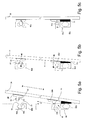
- Fig. 5a to 5c illustrate the assembly of a PV module 1a of Fig. 1 to 4a at two cross rails 60 with the fastening and securing system according to the invention according to the embodiment of the invention Fig. 4a ,
- the bearing clearance S2a is equal to zero by a corresponding dimensioning of the mouth width of the mouth-like opening formed by the angled arm A.
- the mobility of the PV module 1a in the direction of the arrow F2 is essentially ensured by an elastic element 15 which is arranged between the lower transverse rail 60a and the rear side 11 of the PV module 1a.
- the elastic member 15 may, as in the Fig. 5a to 5c be formed in cross-section in particular triangular, oval, circular or square.
- the elastic element 15 is formed rectangular.
- the plane of the cross section is perpendicular to the surface plane of the plate-shaped elements 1 a and such that the fall line 10 (see Fig. 1 ) lies in this cross-sectional plane.
- the elastic element 15 can be produced by cutting lengthwise material strands of rectangular cross-section.
- the elastic member 15 may be made of a soft rubber, silicone or ethylene-propylene-diene rubber (EPDM).
- Soft rubber is a particularly inexpensive and easy-to-use material.
- Silicone or ethylene-propylene-diene rubber (EPDM) are particularly suitable since both materials are particularly UV resistant.
- silicone or ethylene-propylene-diene rubber (EPDM) are particularly resistant to chemicals, in particular to ammonia-containing gases, such as may occur in the vicinity of utility buildings for livestock farming in increased concentrations.
- the elastic element 15 is attached according to an embodiment of the present invention to the PV module 1a and in particular on the surface of the back of the PV module 1a cohesively thereto. If the elastic element 15 is made of silicone, the silicone can be sprayed onto the PV module and thus brought into its desired shape as a support. However, a prefabricated elastic element 15, e.g. ethylene-propylene-diene rubber (EPDM), used to make this integral bond which is adhered to a PV module. In this case, the elastic member 15 is fixed on the PV module by means of an adhesive layer.
- EPDM ethylene-propylene-diene rubber
- the elastic element 15 can in principle already, together with the fastening elements 20 and the securing elements 30a on the back 11 of the PV module 1 a or alternatively on the support surface of the transverse rail 60b cohesively, in particular by gluing, are fixed, ie before the actual assembly on the lower and upper cross rails 60a, 60b.
- Fig. 5a illustrates a first step of mounting the PV module 1a to the upper crossbar 60a and the lower crossbar 60b.
- the PV module 1a is plugged with the opening M formed by the arm A of the securing element 30a on the lower transverse rail 60b.
- the PV module 1 a at an acute angle ⁇ to the mounting plane 7 from the direction of the upper cross rail 60a, ie in the direction of the dashed arrow with a simple tip, with the opening M on the crossbar 60b to be moved. Due to the acute angle ⁇ , the elastic element 15 is compressed between the transverse rail 60b and the back 11, thereby damping forces which occur advantageously when the PV module 1a is inserted.
- Fig. 5b illustrates the next step of the assembly, in which as soon as the opening M engages behind the lower crossbar 60b, the PV module 1a is tilted in the direction of the dashed arrow with a double point, ie in the direction of the mounting plane 7. The tilting takes place so that the anchor body 23 of the fastener 20 is inserted with the snap hook ahead in the groove 61 of the upper crossbar 60a.
- the snap hooks 24 are deflected or pressed by the undercuts 62a and 62b at the opening of the groove 61 of the upper cross rail 60a. Once the anchoring means formed by the anchor body 23 and the snap hook 24 is inserted into the groove 61, the snap hooks snap back into their originally spread position and thus engage behind the undercuts 62a and 62b at the opening of the groove 61st
- Fig. 5c shown installation state in which the bearing surface 22 of the fastener 20 bears against the support surface 65 of the upper cross rail 60a. Further, the contact arm surface 34a of the securing member 30a abuts against the rear side of the lower cross rail 60b so that there is no bearing clearance S3a.
- the clearance S4a in the direction of the fall line 10 is designed to be large enough to compensate for a tolerances in terms of the distances of the mounted crossbars 60 and on the other length changes in the PV module 1 a due to temperature fluctuations.
Landscapes
- Engineering & Computer Science (AREA)
- Architecture (AREA)
- Structural Engineering (AREA)
- Civil Engineering (AREA)
- Chemical & Material Sciences (AREA)
- Thermal Sciences (AREA)
- Physics & Mathematics (AREA)
- Combustion & Propulsion (AREA)
- Mechanical Engineering (AREA)
- General Engineering & Computer Science (AREA)
- Sustainable Energy (AREA)
- Sustainable Development (AREA)
- Life Sciences & Earth Sciences (AREA)
- Roof Covering Using Slabs Or Stiff Sheets (AREA)
- Photovoltaic Devices (AREA)
Applications Claiming Priority (1)
| Application Number | Priority Date | Filing Date | Title |
|---|---|---|---|
| DE102010051468A DE102010051468A1 (de) | 2010-11-17 | 2010-11-17 | Befestigung plattenförmiger Elemente |
Publications (2)
| Publication Number | Publication Date |
|---|---|
| EP2455683A2 true EP2455683A2 (fr) | 2012-05-23 |
| EP2455683A3 EP2455683A3 (fr) | 2014-04-30 |
Family
ID=45062777
Family Applications (1)
| Application Number | Title | Priority Date | Filing Date |
|---|---|---|---|
| EP11009126.1A Withdrawn EP2455683A3 (fr) | 2010-11-17 | 2011-11-17 | Fixation d'éléments en forme de plaques |
Country Status (4)
| Country | Link |
|---|---|
| US (1) | US20120125409A1 (fr) |
| EP (1) | EP2455683A3 (fr) |
| JP (1) | JP2012109573A (fr) |
| DE (1) | DE102010051468A1 (fr) |
Cited By (2)
| Publication number | Priority date | Publication date | Assignee | Title |
|---|---|---|---|---|
| EP3565109A1 (fr) * | 2018-04-13 | 2019-11-06 | Guangdong Hanergy Thin-Film Solar Co., Ltd. | Tuile de production d'énergie solaire monté sur recouvrement |
| EP3090485B1 (fr) * | 2013-12-30 | 2023-03-01 | SunPower Corporation | Matériel de système de puissance solaire à poursuite du soleil et procédé d'assemblage |
Families Citing this family (5)
| Publication number | Priority date | Publication date | Assignee | Title |
|---|---|---|---|---|
| AU2014315407B2 (en) | 2013-09-05 | 2018-12-13 | Alion Energy, Inc. | Systems, vehicles, and methods for maintaining rail-based arrays of photovoltaic modules |
| US9453660B2 (en) | 2013-09-11 | 2016-09-27 | Alion Energy, Inc. | Vehicles and methods for magnetically managing legs of rail-based photovoltaic modules during installation |
| WO2017044566A1 (fr) | 2015-09-11 | 2017-03-16 | Alion Energy, Inc. | Écrans anti-vent pour réseaux photovoltaïques et procédés correspondants |
| US20170331414A1 (en) * | 2016-05-16 | 2017-11-16 | Alion Energy, Inc. | Feet of solar collector support structures, joints between feet of solar collector support structures and concrete, and methods of forming the same |
| DE102023105252A1 (de) | 2023-03-03 | 2024-09-05 | Sevki Özer | Montagesystem und Tragkonstruktion zur Montage mindestens eines plattenförmigen Photovoltaik-Moduls und Solaranlage mit einer derartigen Tragkonstruktion |
Citations (7)
| Publication number | Priority date | Publication date | Assignee | Title |
|---|---|---|---|---|
| FR2538867A1 (fr) | 1983-01-05 | 1984-07-06 | Guerin Gabriel | Dispositif de fixation pour plaques de bardage notamment pour plaques en pierre reconstituee |
| WO1999017063A1 (fr) | 1997-09-30 | 1999-04-08 | Wolfgang Wismeth | Dispositif de fixation pour modules solaires |
| FR2928672A1 (fr) | 2008-03-17 | 2009-09-18 | Opaly Soc Par Actions Simplifi | Dispositif de bardage notamment pour facade ou toiture. |
| DE102008032985A1 (de) | 2008-07-14 | 2010-01-21 | Gehrlicher Solar Ag | Befestigungsstruktur für ein großflächiges Solarmodul und Solarmodul |
| DE102009024615A1 (de) | 2008-06-11 | 2010-02-18 | Schletter Gmbh | Montagesystem für PV-Module |
| DE102008052594A1 (de) | 2008-10-21 | 2010-05-27 | Pauli + Sohn Gmbh Metallwaren | Haltesystem zur Befestigung von Solarmodulen |
| DE202010007658U1 (de) | 2010-06-07 | 2010-08-26 | Energiebau Solarstromsysteme Gmbh | Modulträger |
Family Cites Families (25)
| Publication number | Priority date | Publication date | Assignee | Title |
|---|---|---|---|---|
| CA1265398A (fr) * | 1984-11-01 | 1990-02-06 | Barrie Peter Moore | Amenagement de couvertures |
| US4966631A (en) * | 1989-03-13 | 1990-10-30 | Chronar Corp. | Support for photovoltaic arrays |
| US5143556A (en) * | 1989-03-13 | 1992-09-01 | Matlin Ronald W | Support for photovoltaic arrays |
| US5480494A (en) * | 1993-05-18 | 1996-01-02 | Canon Kabushiki Kaisha | Solar cell module and installation method thereof |
| DE19529351A1 (de) * | 1995-08-09 | 1997-02-13 | Gido Genschorek | Vorrichtung zur Befestigung von plattenförmigen Bauteilen, insbesondere von Solarmodulen und Sonnenkollektoren |
| US5741370A (en) * | 1996-06-27 | 1998-04-21 | Evergreen Solar, Inc. | Solar cell modules with improved backskin and methods for forming same |
| US5762720A (en) * | 1996-06-27 | 1998-06-09 | Evergreen Solar, Inc. | Solar cell modules with integral mounting structure and methods for forming same |
| WO2002041407A1 (fr) * | 2000-11-16 | 2002-05-23 | Kaneka Corporation | Module de batterie solaire, systeme de production d'energie photovoltaique, bloc de support supportant ce module de batterie solaire, et procede d'installation d'un systeme de production d'energie photovoltaique |
| US8141306B2 (en) * | 2004-10-22 | 2012-03-27 | Kyocera Corporation | Solar battery module device and method of installing the same |
| DE202007008614U1 (de) * | 2007-06-15 | 2007-08-16 | Phoenix Solar Ag | Traganordnung für eine Solaranlage, Solaranlage mit einer Mehrzahl von Solarmodulen und Solarmodul hierfür |
| US20090114270A1 (en) * | 2007-07-20 | 2009-05-07 | Robert Stancel | Rapid Mounting System for Solar Modules |
| US8536442B2 (en) * | 2007-09-02 | 2013-09-17 | Nanosolar, Inc. | Slidable mounting system for solar modules |
| EP2063199B1 (fr) * | 2007-11-23 | 2012-05-30 | BELECTRIC Trading GmbH | Arrangement d'un support de fixation avec modules photovoltaïques |
| EP2099077A1 (fr) * | 2008-03-06 | 2009-09-09 | Inventux Technologies AG | Module pour convertir un rayonnement solaire en électricité |
| US20090266352A1 (en) * | 2008-04-24 | 2009-10-29 | Robert Evans Wetmore | Panel and panel mount system |
| TWI529358B (zh) * | 2008-07-14 | 2016-04-11 | 吉赫立確太陽能公司 | 用於寬面太陽能模組之固定裝置以及太陽能模組 |
| US20100059641A1 (en) * | 2008-09-10 | 2010-03-11 | Epv Solar, Inc. | Mounting Systems for Photovoltaic Modules |
| DE102008051249A1 (de) * | 2008-10-10 | 2010-04-29 | Sunfilm Ag | Photovoltaikanlage, Photovoltaikmodul und Verfahren zur Bestückung einer Photovoltaikanlage |
| DE202008015916U1 (de) * | 2008-12-02 | 2009-02-19 | Solarmarkt Ag | Profilanordnung zum Fixieren wenigstens eines Solarmodules an einer Trägerstruktur und Einrichtung mit einem über eine Profilanordnung mit einer Trägerstruktur verbundenen Solarmodul |
| US8240109B2 (en) * | 2009-03-20 | 2012-08-14 | Northern States Metals Company | Support system for solar panels |
| US8256169B2 (en) * | 2009-03-20 | 2012-09-04 | Northern States Metals Company | Support system for solar panels |
| DE202009008931U1 (de) * | 2009-06-29 | 2009-09-24 | Meinhardt, Dirk | Gebäudehülle mit Solarkollektormodul(en) und Montagesystem dafür |
| US20110036028A1 (en) * | 2009-08-17 | 2011-02-17 | Adensis Gmbh | Roof mounting support for photovoltaic modules on uneven roofs |
| US8984818B2 (en) * | 2010-10-06 | 2015-03-24 | Sunrun South Llc | Snap-in mounting systems for laminate solar panels |
| US8656658B2 (en) * | 2010-10-20 | 2014-02-25 | Miasole | Retainers for attaching photovoltaic modules to mounting structures |
-
2010
- 2010-11-17 DE DE102010051468A patent/DE102010051468A1/de not_active Withdrawn
-
2011
- 2011-11-17 US US13/298,392 patent/US20120125409A1/en not_active Abandoned
- 2011-11-17 JP JP2011251802A patent/JP2012109573A/ja active Pending
- 2011-11-17 EP EP11009126.1A patent/EP2455683A3/fr not_active Withdrawn
Patent Citations (7)
| Publication number | Priority date | Publication date | Assignee | Title |
|---|---|---|---|---|
| FR2538867A1 (fr) | 1983-01-05 | 1984-07-06 | Guerin Gabriel | Dispositif de fixation pour plaques de bardage notamment pour plaques en pierre reconstituee |
| WO1999017063A1 (fr) | 1997-09-30 | 1999-04-08 | Wolfgang Wismeth | Dispositif de fixation pour modules solaires |
| FR2928672A1 (fr) | 2008-03-17 | 2009-09-18 | Opaly Soc Par Actions Simplifi | Dispositif de bardage notamment pour facade ou toiture. |
| DE102009024615A1 (de) | 2008-06-11 | 2010-02-18 | Schletter Gmbh | Montagesystem für PV-Module |
| DE102008032985A1 (de) | 2008-07-14 | 2010-01-21 | Gehrlicher Solar Ag | Befestigungsstruktur für ein großflächiges Solarmodul und Solarmodul |
| DE102008052594A1 (de) | 2008-10-21 | 2010-05-27 | Pauli + Sohn Gmbh Metallwaren | Haltesystem zur Befestigung von Solarmodulen |
| DE202010007658U1 (de) | 2010-06-07 | 2010-08-26 | Energiebau Solarstromsysteme Gmbh | Modulträger |
Cited By (2)
| Publication number | Priority date | Publication date | Assignee | Title |
|---|---|---|---|---|
| EP3090485B1 (fr) * | 2013-12-30 | 2023-03-01 | SunPower Corporation | Matériel de système de puissance solaire à poursuite du soleil et procédé d'assemblage |
| EP3565109A1 (fr) * | 2018-04-13 | 2019-11-06 | Guangdong Hanergy Thin-Film Solar Co., Ltd. | Tuile de production d'énergie solaire monté sur recouvrement |
Also Published As
| Publication number | Publication date |
|---|---|
| EP2455683A3 (fr) | 2014-04-30 |
| US20120125409A1 (en) | 2012-05-24 |
| JP2012109573A (ja) | 2012-06-07 |
| DE102010051468A1 (de) | 2012-05-24 |
Similar Documents
| Publication | Publication Date | Title |
|---|---|---|
| EP2297790B1 (fr) | Système d'assemblage pour un module photovoltaïque | |
| DE102008055937B4 (de) | Solarmodulmontagesystem mit zumindest zwei Halteschienen, einem Photovoltaikmodul und mindestens einem Klemmstück sowie Verfahren für die Montage eines Solarmodulmontagesystems | |
| EP2315982B1 (fr) | Structure de fixation destinée à un module solaire de grande surface et module solaire | |
| EP2238393B1 (fr) | Système de fixation de modules solaires | |
| DE102013207827B4 (de) | Vorrichtung zum Befestigen von Solarmodulen und Dach | |
| EP2307821A2 (fr) | Profilé de retenue et profilé d'étanchéité pour module en forme de plaque | |
| EP2242112B1 (fr) | Système de recouvrement de toit pour modules solaires | |
| DE102010051468A1 (de) | Befestigung plattenförmiger Elemente | |
| EP2317246B1 (fr) | Cadre en plusieurs parties pour module en forme de plaque | |
| EP2327940A1 (fr) | Installation photovoltaïque dotée d'éléments de réflexion | |
| EP2278236A2 (fr) | Pince à double niveau pour modules photovoltaïques | |
| DE202011001320U1 (de) | Gestell | |
| EP1845319A2 (fr) | Dispositif de fixation pour le montage sur le toit d'un élément d'accessoire de toit pouvant être monté sur un toit incliné | |
| DE102013204954B4 (de) | Halteeinrichtung für Photovoltaikmodule | |
| DE102009022731A1 (de) | Photovoltaische Anlage aus Dünnschichtsolarmodulen | |
| EP2221557A1 (fr) | Liaison crantée | |
| EP2679929A1 (fr) | Système de montage et d'étanchéité pour l'intégration d'une multitude de modules en forme de plaques dans un toit incliné | |
| EP2390432B1 (fr) | Construction suspendue | |
| EP2423622B1 (fr) | Dispositif de fixation avec éléments de montage et rail de support | |
| EP2194341A2 (fr) | Verrouillage de module | |
| EP1985944A1 (fr) | Installation de module solaire et de collecteur solaire (SolarDach F) | |
| DE102009055722A1 (de) | Halterungsvorrichtung, insbesondere für solare Module auf Trapezblechen | |
| EP2293346A2 (fr) | Dispositif de fixation pour modules photovoltaïques, solaires et/ou hybrides | |
| WO2013182623A2 (fr) | Ensemble de montage pour le montage d'éléments plats sur le toit d'un bâtiment | |
| EP2356293A2 (fr) | Système de toiture intégré, fixation de profilés d'insertion sur des panneaux sandwichs présentant des rainures de dégagement |
Legal Events
| Date | Code | Title | Description |
|---|---|---|---|
| PUAI | Public reference made under article 153(3) epc to a published international application that has entered the european phase |
Free format text: ORIGINAL CODE: 0009012 |
|
| AK | Designated contracting states |
Kind code of ref document: A2 Designated state(s): AL AT BE BG CH CY CZ DE DK EE ES FI FR GB GR HR HU IE IS IT LI LT LU LV MC MK MT NL NO PL PT RO RS SE SI SK SM TR |
|
| AX | Request for extension of the european patent |
Extension state: BA ME |
|
| RIN1 | Information on inventor provided before grant (corrected) |
Inventor name: HANSELMANN, TIMO Inventor name: BARIE, MATTHIAS Inventor name: BELSCHNER, WERNER |
|
| PUAL | Search report despatched |
Free format text: ORIGINAL CODE: 0009013 |
|
| AK | Designated contracting states |
Kind code of ref document: A3 Designated state(s): AL AT BE BG CH CY CZ DE DK EE ES FI FR GB GR HR HU IE IS IT LI LT LU LV MC MK MT NL NO PL PT RO RS SE SI SK SM TR |
|
| AX | Request for extension of the european patent |
Extension state: BA ME |
|
| RIC1 | Information provided on ipc code assigned before grant |
Ipc: F24J 2/52 20060101AFI20140325BHEP |
|
| STAA | Information on the status of an ep patent application or granted ep patent |
Free format text: STATUS: THE APPLICATION IS DEEMED TO BE WITHDRAWN |
|
| 18D | Application deemed to be withdrawn |
Effective date: 20141031 |