EP2455754A2 - Ultraschallsystem und Verfahren zur Bereitstellung eines vergrößerten Bildes - Google Patents
Ultraschallsystem und Verfahren zur Bereitstellung eines vergrößerten Bildes Download PDFInfo
- Publication number
- EP2455754A2 EP2455754A2 EP11189305A EP11189305A EP2455754A2 EP 2455754 A2 EP2455754 A2 EP 2455754A2 EP 11189305 A EP11189305 A EP 11189305A EP 11189305 A EP11189305 A EP 11189305A EP 2455754 A2 EP2455754 A2 EP 2455754A2
- Authority
- EP
- European Patent Office
- Prior art keywords
- ultrasound
- user input
- enlarged
- image
- input information
- Prior art date
- Legal status (The legal status is an assumption and is not a legal conclusion. Google has not performed a legal analysis and makes no representation as to the accuracy of the status listed.)
- Withdrawn
Links
Images




Classifications
-
- G—PHYSICS
- G01—MEASURING; TESTING
- G01N—INVESTIGATING OR ANALYSING MATERIALS BY DETERMINING THEIR CHEMICAL OR PHYSICAL PROPERTIES
- G01N29/00—Investigating or analysing materials by the use of ultrasonic, sonic or infrasonic waves; Visualisation of the interior of objects by transmitting ultrasonic or sonic waves through the object
- G01N29/04—Analysing solids
- G01N29/06—Visualisation of the interior, e.g. acoustic microscopy
- G01N29/0654—Imaging
-
- A—HUMAN NECESSITIES
- A61—MEDICAL OR VETERINARY SCIENCE; HYGIENE
- A61B—DIAGNOSIS; SURGERY; IDENTIFICATION
- A61B8/00—Diagnosis using ultrasonic, sonic or infrasonic waves
- A61B8/46—Ultrasonic, sonic or infrasonic diagnostic devices with special arrangements for interfacing with the operator or the patient
- A61B8/461—Displaying means of special interest
-
- A—HUMAN NECESSITIES
- A61—MEDICAL OR VETERINARY SCIENCE; HYGIENE
- A61B—DIAGNOSIS; SURGERY; IDENTIFICATION
- A61B8/00—Diagnosis using ultrasonic, sonic or infrasonic waves
- A61B8/52—Devices using data or image processing specially adapted for diagnosis using ultrasonic, sonic or infrasonic waves
- A61B8/5207—Devices using data or image processing specially adapted for diagnosis using ultrasonic, sonic or infrasonic waves involving processing of raw data to produce diagnostic data, e.g. for generating an image
-
- G—PHYSICS
- G01—MEASURING; TESTING
- G01S—RADIO DIRECTION-FINDING; RADIO NAVIGATION; DETERMINING DISTANCE OR VELOCITY BY USE OF RADIO WAVES; LOCATING OR PRESENCE-DETECTING BY USE OF THE REFLECTION OR RERADIATION OF RADIO WAVES; ANALOGOUS ARRANGEMENTS USING OTHER WAVES
- G01S7/00—Details of systems according to groups G01S13/00, G01S15/00, G01S17/00
- G01S7/52—Details of systems according to groups G01S13/00, G01S15/00, G01S17/00 of systems according to group G01S15/00
- G01S7/52017—Details of systems according to groups G01S13/00, G01S15/00, G01S17/00 of systems according to group G01S15/00 particularly adapted to short-range imaging
- G01S7/52023—Details of receivers
- G01S7/52034—Data rate converters
-
- G—PHYSICS
- G01—MEASURING; TESTING
- G01S—RADIO DIRECTION-FINDING; RADIO NAVIGATION; DETERMINING DISTANCE OR VELOCITY BY USE OF RADIO WAVES; LOCATING OR PRESENCE-DETECTING BY USE OF THE REFLECTION OR RERADIATION OF RADIO WAVES; ANALOGOUS ARRANGEMENTS USING OTHER WAVES
- G01S7/00—Details of systems according to groups G01S13/00, G01S15/00, G01S17/00
- G01S7/52—Details of systems according to groups G01S13/00, G01S15/00, G01S17/00 of systems according to group G01S15/00
- G01S7/52017—Details of systems according to groups G01S13/00, G01S15/00, G01S17/00 of systems according to group G01S15/00 particularly adapted to short-range imaging
- G01S7/52053—Display arrangements
- G01S7/52057—Cathode ray tube displays
- G01S7/5206—Two-dimensional coordinated display of distance and direction; B-scan display
- G01S7/52063—Sector scan display
-
- G—PHYSICS
- G06—COMPUTING OR CALCULATING; COUNTING
- G06T—IMAGE DATA PROCESSING OR GENERATION, IN GENERAL
- G06T3/00—Geometric image transformations in the plane of the image
- G06T3/40—Scaling of whole images or parts thereof, e.g. expanding or contracting
- G06T3/4023—Scaling of whole images or parts thereof, e.g. expanding or contracting based on decimating pixels or lines of pixels; based on inserting pixels or lines of pixels
-
- A—HUMAN NECESSITIES
- A61—MEDICAL OR VETERINARY SCIENCE; HYGIENE
- A61B—DIAGNOSIS; SURGERY; IDENTIFICATION
- A61B8/00—Diagnosis using ultrasonic, sonic or infrasonic waves
- A61B8/46—Ultrasonic, sonic or infrasonic diagnostic devices with special arrangements for interfacing with the operator or the patient
- A61B8/467—Ultrasonic, sonic or infrasonic diagnostic devices with special arrangements for interfacing with the operator or the patient characterised by special input means
- A61B8/469—Ultrasonic, sonic or infrasonic diagnostic devices with special arrangements for interfacing with the operator or the patient characterised by special input means for selection of a region of interest
-
- G—PHYSICS
- G01—MEASURING; TESTING
- G01N—INVESTIGATING OR ANALYSING MATERIALS BY DETERMINING THEIR CHEMICAL OR PHYSICAL PROPERTIES
- G01N2291/00—Indexing codes associated with group G01N29/00
- G01N2291/02—Indexing codes associated with the analysed material
- G01N2291/024—Mixtures
- G01N2291/02466—Biological material, e.g. blood
-
- G—PHYSICS
- G01—MEASURING; TESTING
- G01N—INVESTIGATING OR ANALYSING MATERIALS BY DETERMINING THEIR CHEMICAL OR PHYSICAL PROPERTIES
- G01N2291/00—Indexing codes associated with group G01N29/00
- G01N2291/04—Wave modes and trajectories
- G01N2291/044—Internal reflections (echoes), e.g. on walls or defects
-
- G—PHYSICS
- G01—MEASURING; TESTING
- G01S—RADIO DIRECTION-FINDING; RADIO NAVIGATION; DETERMINING DISTANCE OR VELOCITY BY USE OF RADIO WAVES; LOCATING OR PRESENCE-DETECTING BY USE OF THE REFLECTION OR RERADIATION OF RADIO WAVES; ANALOGOUS ARRANGEMENTS USING OTHER WAVES
- G01S7/00—Details of systems according to groups G01S13/00, G01S15/00, G01S17/00
- G01S7/52—Details of systems according to groups G01S13/00, G01S15/00, G01S17/00 of systems according to group G01S15/00
- G01S7/52017—Details of systems according to groups G01S13/00, G01S15/00, G01S17/00 of systems according to group G01S15/00 particularly adapted to short-range imaging
- G01S7/52053—Display arrangements
- G01S7/52057—Cathode ray tube displays
- G01S7/52074—Composite displays, e.g. split-screen displays; Combination of multiple images or of images and alphanumeric tabular information
Definitions
- the present invention relates to ultrasound systems, and more particularly to an ultrasound system and method for providing an enlarged image.
- an ultrasound system Since an ultrasound system has noninvasive and nondestructive characteristics, it has been widely used in the medical fields to acquire information on the inner parts of a target object.
- the ultrasound system may provide doctors with high-resolution images of the inner parts of a target object without any surgical operation. Hence, the ultrasound system is very important in the medical fields.
- the ultrasound system forms an ultrasound image by transmitting an ultrasound signal to a target object and receiving an ultrasound echo signal reflected from the target object through an ultrasound probe.
- the ultrasound system provides an image zoom function to enlarge an ultrasound image. Specifically, when a region of interest, which is to be enlarged, is set in an ultrasound image, the ultrasound system provides read zoom and write zoom functions that enlarge an image corresponding to the region of interest.
- the read zoom function is to enlarge an ultrasound image during an output procedure for display on a display unit after the scan conversion.
- the present invention is directed to an ultrasound system and method for providing an enlarged image without any degradation of image quality by performing data processing corresponding to a read zoom function upon ultrasound data within a region of interest before scan conversion.
- an ultrasound system includes: an ultrasound data acquisition unit configured to transmit an ultrasound signal to a target object and receive an ultrasound echo signal reflected from the target object to acquire ultrasound data; a user input unit configured to receive user input information; and a processor connected to the ultrasound data acquisition unit and the user input unit, the processor being configured to extract ultrasound data corresponding to the user input information from the acquired ultrasound data, perform a decimation process on the extracted ultrasound data based on a zoom ratio corresponding to the user input information, and form an enlarged image corresponding to the zoom ratio by using the decimated ultrasound data.
- a method of providing an enlarged image includes: a) transmitting an ultrasound signal to a target object and receiving an ultrasound echo signal reflected from the target object to acquire ultrasound data; b) extracting ultrasound data corresponding to first user input information from the acquired ultrasound data; c) performing a decimation process on the extracted ultrasound data based on a zoom ratio corresponding to second user input information; and d) forming an enlarged image corresponding to the zoom ratio by using the decimated ultrasound data.
- FIG. 1 is a block diagram of an ultrasound system in accordance with an embodiment of the present invention.
- the ultrasound system 100 includes an ultrasound data acquisition unit 110, a user input unit 120, a storage unit 130, a processor 140 and a display unit 150.
- the ultrasound data acquisition unit 110 acquires ultrasound data by transmitting an ultrasound signal to a target object and receiving an ultrasound echo signal reflected from the target obj ect.
- FIG. 2 is a block diagram of the ultrasound data acquisition unit in accordance with an embodiment of the present invention.
- the ultrasound data acquisition unit 110 includes an ultrasound probe 210, a transmission signal generator 220, a beam former 230 and an ultrasound data generator 240.
- the ultrasound probe 210 includes a plurality of transducer elements (not shown) for reciprocal conversion between an electric signal and an ultrasound signal.
- the ultrasound probe 210 transmits an ultrasound signal to a target object along a plurality of scan lines and receives an ultrasound echo signal reflected from the target object to thereby form a reception signal.
- the reception signal is an analog signal.
- the ultrasound probe 210 includes a convex probe, a linear probe or the like. However, the ultrasound probe 210 is not limited thereto.
- the transmission signal generator 220 controls the transmission of the ultrasound signal according to a desired ultrasound image.
- the transmission signal generator 220 generates a transmission signal to be applied to the ultrasound probe 210, considering the transducer elements and focusing points.
- the ultrasound image includes a brightness mode (B mode) image.
- B mode brightness mode
- the ultrasound image is not limited thereto.
- the beam former 230 performs an analog-to-digital conversion on the reception signal provided from the ultrasound probe 210 to form a digital signal. In addition, the beam former 230 further performs receive-focusing upon the digital signal by considering the transducer elements and the focusing points to form a receive-focused signal.
- the ultrasound data generator 240 generates ultrasound data corresponding to the ultrasound image by using the receive-focused signal provided from the beam former 230.
- the ultrasound data includes radio frequency (RF) data.
- RF radio frequency
- the ultrasound data is not limited thereto.
- the ultrasound data generator 240 may perform a variety of signal processing (e.g., gain control) on the receive-focused signal to generate the ultrasound data.
- the user input unit 120 receives user input information.
- the user input information includes first user input information and second user input information.
- the first user input information is used to set a region of interest RI, which is to be enlarged, in an ultrasound image UI.
- the second input information is used to set a zoom ratio of an enlarged image.
- the user input unit 120 includes a control panel, a track ball, a mouse, a keyboard or the like. However, the user input unit 120 is not limited thereto.
- the storage unit 130 stores the ultrasound data acquired by the ultrasound data acquisition unit 110. Further, the storage unit 130 may store the user input information received from the user input unit 120.
- the processor 140 is connected to the ultrasound data acquisition unit 110, the user input unit 120 and the storage unit 130.
- the processor 140 includes a central processing unit (CPU), a microprocessor, a graphic processing unit (GPU) or the like.
- CPU central processing unit
- GPU graphic processing unit
- the processor 140 is not limited thereto.
- FIG. 4 is a flowchart showing a procedure of providing an enlarged image in accordance with a first embodiment of the present invention.
- the processor 140 forms the ultrasound image UI, as shown in FIG. 3 , using the ultrasound data provided from the ultrasound data acquisition unit 110 at S402.
- the ultrasound image UI may be displayed on the display unit 150.
- the user input unit 120 may allow the user to set the region of interest RI in the ultrasound image UI displayed on the display unit 150.
- the processor 140 forms the ultrasound image using the ultrasound data provided from the ultrasound data acquisition unit 110, the invention is not limited thereto.
- the processor 140 may form the ultrasound image using the ultrasound data stored in the storage unit 130.
- the processor 140 When the processor 140 receives the user input information (that is, the first user input information) from the user input unit 120, the processor 140 sets the region of interest RI in the ultrasound image UI as shown in FIG. 3 based on the first user input information at S404 and searches the storage unit 130 to extract ultrasound data corresponding to the region of interest RI at S406.
- the processor 140 When the processor 140 receives the user input information (that is, the second user input information) from the user input unit 120, the processor 140 sets a decimation factor for performing a decimation process of sampling the ultrasound data extracted from the storage unit 130 based on the second user input information at S408. For example, as shown in FIG. 5 , the processor 140 multiplies a preset decimation factor (that is, a screen size (I RH , I RW ) of the display unit 150) by a zoom ratio (Z R ) corresponding to the second user input information to reset a decimation factor (I RH ⁇ Z R, I RW ⁇ Z R ) .
- a preset decimation factor that is, a screen size (I RH , I RW ) of the display unit 150
- Z R zoom ratio
- the processor 140 performs a decimation process on the ultrasound data extracted from the storage unit 130 based on the reset decimation factor at S410. For example, as shown in FIG. 5 , the processor 140 performs a decimation process on the extracted ultrasound data (SD H ⁇ SD W ) based on the reset decimation factor (I RH ⁇ Z R , I RW ⁇ Z R ).
- the processor 140 performs scan conversion on the decimated ultrasound data to form an enlarged image at S412.
- FIG. 6 is a flowchart showing a procedure of providing an enlarged image in accordance with a second embodiment of the present invention.
- the processor 140 extracts ultrasound data stored in the storage unit 120 at S602.
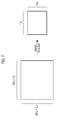
- the processor 140 When the processor 140 receives the user input information (that is, the second user input information) from the user input unit 120, the processor 140 performs scan conversion upon the extracted ultrasound data for enlargement by a zoom ratio corresponding to the second user input information to form an ultrasound image at S604. For example, as shown in FIG. 7 , the processor 140 performs scan conversion upon the extracted ultrasound data (SD H ⁇ SD W ) for enlargement by a zoom ratio (Z R ) corresponding to the second user input information to form an ultrasound image DUI.
- the processor 140 performs scan conversion upon the extracted ultrasound data (SD H ⁇ SD W ) for enlargement by a zoom ratio (Z R ) corresponding to the second user input information to form an ultrasound image DUI.
- zoom scan conversion is performed on the ultrasound data stored in the storage unit 120
- the invention is not limited thereto.
- the zoom scan conversion may be performed on the ultrasound data provided from the ultrasound data acquisition unit 110.
- the processor 140 performs image scaling on the ultrasound image to reduce a size thereof at S606.
- the reduced ultrasound image may be displayed on the display unit 150.
- the user input unit 120 may allow the user to set the region of interest RI in the ultrasound image UI displayed on the display unit 150.
- the processor 140 performs image scaling on the zoom-scan-converted ultrasound image data by a zoom ratio corresponding to the screen size (I RH , I RW ) of the display unit 150 to reduce the size of the ultrasound image.
- the processor 140 When the processor 140 receives the user input information (that is, the first user input information) from the user input unit 120, the processor 140 sets the region of interest in the zoom-scan-converted ultrasound image based on the first user input information at S608. For example, the processor 140 sets the region of interest in the reduced ultrasound image based on the first user input information, enlarges the set region of interest by a zoom ratio corresponding to the screen size (I RH , I RW ) of the display unit 150, and sets the enlarged region of interest in the zoom-scan-converted ultrasound image.
- the processor 140 sets the region of interest in the reduced ultrasound image based on the first user input information, enlarges the set region of interest by a zoom ratio corresponding to the screen size (I RH , I RW ) of the display unit 150, and sets the enlarged region of interest in the zoom-scan-converted ultrasound image.
- the processor 140 extracts an enlarged image corresponding to the enlarged region of interest from the zoom-scan-converted ultrasound image at S610.
- the display unit 150 displays the ultrasound image formed by the processor 140. Further, the display unit 150 displays the enlarged image formed by the processor 140. For example, as shown in FIG. 8 or 9 , the display unit 150 includes a wide-view display. Thus, the ultrasound image UI and the enlarged image DUI may be displayed in the same size, as shown in FIG. 8 or 9 .
Landscapes
- Engineering & Computer Science (AREA)
- Life Sciences & Earth Sciences (AREA)
- Physics & Mathematics (AREA)
- Health & Medical Sciences (AREA)
- General Physics & Mathematics (AREA)
- General Health & Medical Sciences (AREA)
- Pathology (AREA)
- Medical Informatics (AREA)
- Computer Networks & Wireless Communication (AREA)
- Nuclear Medicine, Radiotherapy & Molecular Imaging (AREA)
- Remote Sensing (AREA)
- Radiology & Medical Imaging (AREA)
- Biomedical Technology (AREA)
- Heart & Thoracic Surgery (AREA)
- Radar, Positioning & Navigation (AREA)
- Molecular Biology (AREA)
- Surgery (AREA)
- Animal Behavior & Ethology (AREA)
- Biophysics (AREA)
- Public Health (AREA)
- Veterinary Medicine (AREA)
- Theoretical Computer Science (AREA)
- Computer Vision & Pattern Recognition (AREA)
- Acoustics & Sound (AREA)
- Chemical & Material Sciences (AREA)
- Analytical Chemistry (AREA)
- Biochemistry (AREA)
- Immunology (AREA)
- Ultra Sonic Daignosis Equipment (AREA)
Applications Claiming Priority (1)
| Application Number | Priority Date | Filing Date | Title |
|---|---|---|---|
| KR1020100114842A KR101175481B1 (ko) | 2010-11-18 | 2010-11-18 | 확대 영상을 제공하는 초음파 시스템 및 방법 |
Publications (2)
| Publication Number | Publication Date |
|---|---|
| EP2455754A2 true EP2455754A2 (de) | 2012-05-23 |
| EP2455754A3 EP2455754A3 (de) | 2013-04-24 |
Family
ID=44992761
Family Applications (1)
| Application Number | Title | Priority Date | Filing Date |
|---|---|---|---|
| EP11189305.3A Withdrawn EP2455754A3 (de) | 2010-11-18 | 2011-11-16 | Ultraschallsystem und Verfahren zur Bereitstellung eines vergrößerten Bildes |
Country Status (3)
| Country | Link |
|---|---|
| US (1) | US20120130244A1 (de) |
| EP (1) | EP2455754A3 (de) |
| KR (1) | KR101175481B1 (de) |
Cited By (2)
| Publication number | Priority date | Publication date | Assignee | Title |
|---|---|---|---|---|
| CN105338909A (zh) * | 2013-04-30 | 2016-02-17 | 爱飞纽医疗机械贸易有限公司 | 影像放大方法和用于该影像放大方法的超声波医疗装置 |
| CN110248607A (zh) * | 2017-01-23 | 2019-09-17 | 奥林巴斯株式会社 | 超声波观测装置、超声波观测装置的工作方法、超声波观测装置的工作程序 |
Families Citing this family (9)
| Publication number | Priority date | Publication date | Assignee | Title |
|---|---|---|---|---|
| JP2013116138A (ja) * | 2011-12-01 | 2013-06-13 | Sony Corp | 画像処理装置及び方法 |
| US10667790B2 (en) | 2012-03-26 | 2020-06-02 | Teratech Corporation | Tablet ultrasound system |
| US9877699B2 (en) | 2012-03-26 | 2018-01-30 | Teratech Corporation | Tablet ultrasound system |
| DE112013007011T5 (de) * | 2013-04-30 | 2016-01-14 | Alpinion Medical Systems Co., Ltd. | Bildvergrösserungsverfahren und medizinische Ultraschallvorrichtung dafür |
| KR101534089B1 (ko) * | 2013-06-25 | 2015-07-06 | 삼성메디슨 주식회사 | 초음파 진단 장치 및 그 동작방법 |
| EP3000401B1 (de) | 2014-09-23 | 2022-11-09 | Samsung Medison Co., Ltd. | Verfahren und vorrichtung zur erzeugung eines ultraschallbildes |
| ES2634025B2 (es) * | 2016-10-17 | 2018-03-02 | Dispositivos Médicos Flecho, S.L. | Dispositivo de ecografía portátil para el guiado de punciones transcutáneas |
| JP2022138415A (ja) * | 2021-03-10 | 2022-09-26 | コニカミノルタ株式会社 | 超音波診断装置、決定方法および決定プログラム |
| JP7828222B2 (ja) * | 2022-04-07 | 2026-03-11 | 富士フイルム株式会社 | 超音波診断装置及びビーム形成方法 |
Family Cites Families (12)
| Publication number | Priority date | Publication date | Assignee | Title |
|---|---|---|---|---|
| US5471989A (en) * | 1994-10-12 | 1995-12-05 | Advanced Technology Laboratories, Inc. | Ultrasonic diagnostic imaging with enhanced zoom |
| US5904652A (en) * | 1995-06-29 | 1999-05-18 | Teratech Corporation | Ultrasound scan conversion with spatial dithering |
| US5919137A (en) * | 1996-12-04 | 1999-07-06 | Acuson Corporation | Ultrasonic diagnostic imaging system with programmable acoustic signal processor |
| US6135956A (en) * | 1998-10-01 | 2000-10-24 | Atl Ultrasound, Inc. | Ultrasonic diagnostic imaging system with spatial compounding of resampled image data |
| US6413217B1 (en) * | 2000-03-30 | 2002-07-02 | Ge Medical Systems Global Technology Company, Llc | Ultrasound enlarged image display techniques |
| US20110058036A1 (en) * | 2000-11-17 | 2011-03-10 | E-Watch, Inc. | Bandwidth management and control |
| US6925200B2 (en) * | 2000-11-22 | 2005-08-02 | R2 Technology, Inc. | Graphical user interface for display of anatomical information |
| KR100751852B1 (ko) * | 2003-12-31 | 2007-08-27 | 주식회사 메디슨 | 대상체의 3차원 초음파 데이터를 이용하여 그 단면을디스플레이하는 장치 및 방법 |
| US7864347B2 (en) * | 2005-06-27 | 2011-01-04 | Xerox Corporation | Systems and methods that provide custom region scan with preview image on a multifunction device |
| US7694234B2 (en) * | 2005-08-04 | 2010-04-06 | Microsoft Corporation | Virtual magnifying glass with on-the fly control functionalities |
| US8396804B1 (en) * | 2006-07-19 | 2013-03-12 | Mvisum, Inc. | System for remote review of clinical data |
| WO2010005571A2 (en) * | 2008-07-09 | 2010-01-14 | Innurvation, Inc. | Displaying image data from a scanner capsule |
-
2010
- 2010-11-18 KR KR1020100114842A patent/KR101175481B1/ko active Active
-
2011
- 2011-11-16 EP EP11189305.3A patent/EP2455754A3/de not_active Withdrawn
- 2011-11-17 US US13/298,914 patent/US20120130244A1/en not_active Abandoned
Non-Patent Citations (1)
| Title |
|---|
| None |
Cited By (3)
| Publication number | Priority date | Publication date | Assignee | Title |
|---|---|---|---|---|
| CN105338909A (zh) * | 2013-04-30 | 2016-02-17 | 爱飞纽医疗机械贸易有限公司 | 影像放大方法和用于该影像放大方法的超声波医疗装置 |
| CN110248607A (zh) * | 2017-01-23 | 2019-09-17 | 奥林巴斯株式会社 | 超声波观测装置、超声波观测装置的工作方法、超声波观测装置的工作程序 |
| CN110248607B (zh) * | 2017-01-23 | 2021-09-24 | 奥林巴斯株式会社 | 超声波观测装置、超声波观测装置的工作方法、存储介质 |
Also Published As
| Publication number | Publication date |
|---|---|
| KR101175481B1 (ko) | 2012-08-20 |
| US20120130244A1 (en) | 2012-05-24 |
| EP2455754A3 (de) | 2013-04-24 |
| KR20120053626A (ko) | 2012-05-29 |
Similar Documents
| Publication | Publication Date | Title |
|---|---|---|
| EP2455754A2 (de) | Ultraschallsystem und Verfahren zur Bereitstellung eines vergrößerten Bildes | |
| KR20120041052A (ko) | 위상 배열 프로브에 기초하여 초음파 공간 합성 영상을 제공하는 초음파 시스템 및 방법 | |
| US20110137168A1 (en) | Providing a three-dimensional ultrasound image based on a sub region of interest in an ultrasound system | |
| KR101120794B1 (ko) | 움직임 영상을 제공하는 초음파 시스템 | |
| KR20120086585A (ko) | 불투명도 설정부를 구비하는 초음파 시스템 | |
| CN113491537A (zh) | 超声波诊断装置以及存储介质 | |
| KR101390186B1 (ko) | 시간에 따른 혈류 변화를 나타내는 부가 정보를 제공하는 초음파 시스템 및 방법 | |
| KR20080022980A (ko) | 영상 처리 시스템 및 방법 | |
| JP5390645B2 (ja) | 超音波診断装置 | |
| KR101286401B1 (ko) | 미리 보기 영상을 제공하는 초음파 시스템 및 방법 | |
| KR101126891B1 (ko) | 슬라이스 영상을 제공하는 초음파 시스템 및 방법 | |
| US20200077983A1 (en) | Ultrasonic diagnostic apparatus, medical image processing apparatus, and non-transitory computer medium storing computer program | |
| KR101348767B1 (ko) | 확대 영상을 형성하는 초음파 시스템 및 방법 | |
| US20140276045A1 (en) | Method and apparatus for processing ultrasound data using scan line information | |
| JP4851078B2 (ja) | 超音波イメージング装置 | |
| EP4295781A1 (de) | Bildanzeigevorrichtung und steuerungsverfahren für bildanzeigevorrichtung | |
| EP2336804B1 (de) | Ultraschallssystem und Verfahren zur Bereitstellung eines Dopplerschalls | |
| KR101055528B1 (ko) | Oh를 제공하는 초음파 시스템 및 방법 | |
| JP2014239841A (ja) | 超音波診断装置、医用画像処理装置及び制御プログラム | |
| JP4693467B2 (ja) | 超音波診断装置及び画像処理方法 | |
| JP7399621B2 (ja) | 超音波診断装置、情報処理装置及び情報処理プログラム | |
| JP7545794B2 (ja) | 超音波診断装置、医用画像処理装置、及び超音波画像表示プログラム | |
| CN121081023A (zh) | 一种超声检查的进度控制方法、超声设备及存储介质 | |
| KR20110082756A (ko) | 디스플레이부의 회전에 기초하여 초음파 영상의 디스플레이를 설정하는 초음파 시스템 및 방법 | |
| CN121465631A (zh) | 超声波图像处理装置、超声波诊断系统及超声波图像处理方法 |
Legal Events
| Date | Code | Title | Description |
|---|---|---|---|
| PUAI | Public reference made under article 153(3) epc to a published international application that has entered the european phase |
Free format text: ORIGINAL CODE: 0009012 |
|
| AK | Designated contracting states |
Kind code of ref document: A2 Designated state(s): AL AT BE BG CH CY CZ DE DK EE ES FI FR GB GR HR HU IE IS IT LI LT LU LV MC MK MT NL NO PL PT RO RS SE SI SK SM TR |
|
| AX | Request for extension of the european patent |
Extension state: BA ME |
|
| PUAL | Search report despatched |
Free format text: ORIGINAL CODE: 0009013 |
|
| AK | Designated contracting states |
Kind code of ref document: A3 Designated state(s): AL AT BE BG CH CY CZ DE DK EE ES FI FR GB GR HR HU IE IS IT LI LT LU LV MC MK MT NL NO PL PT RO RS SE SI SK SM TR |
|
| AX | Request for extension of the european patent |
Extension state: BA ME |
|
| RIC1 | Information provided on ipc code assigned before grant |
Ipc: G01N 29/024 20060101AFI20130318BHEP Ipc: G01N 29/06 20060101ALI20130318BHEP Ipc: G01S 7/52 20060101ALI20130318BHEP Ipc: G01N 29/07 20060101ALI20130318BHEP Ipc: A61B 8/00 20060101ALI20130318BHEP |
|
| RIC1 | Information provided on ipc code assigned before grant |
Ipc: G01N 29/024 20060101AFI20130409BHEP Ipc: G01N 29/07 20060101ALI20130409BHEP Ipc: G01S 7/52 20060101ALI20130409BHEP Ipc: G01N 29/06 20060101ALI20130409BHEP Ipc: A61B 8/00 20060101ALI20130409BHEP |
|
| 17P | Request for examination filed |
Effective date: 20131023 |
|
| RBV | Designated contracting states (corrected) |
Designated state(s): AL AT BE BG CH CY CZ DE DK EE ES FI FR GB GR HR HU IE IS IT LI LT LU LV MC MK MT NL NO PL PT RO RS SE SI SK SM TR |
|
| 17Q | First examination report despatched |
Effective date: 20170906 |
|
| STAA | Information on the status of an ep patent application or granted ep patent |
Free format text: STATUS: THE APPLICATION IS DEEMED TO BE WITHDRAWN |
|
| 18D | Application deemed to be withdrawn |
Effective date: 20180117 |