EP2455890A2 - Bildverarbeitungssystem, Bildverarbeitungsvorrichtung und Bildverarbeitungsprogramm - Google Patents
Bildverarbeitungssystem, Bildverarbeitungsvorrichtung und Bildverarbeitungsprogramm Download PDFInfo
- Publication number
- EP2455890A2 EP2455890A2 EP11164956A EP11164956A EP2455890A2 EP 2455890 A2 EP2455890 A2 EP 2455890A2 EP 11164956 A EP11164956 A EP 11164956A EP 11164956 A EP11164956 A EP 11164956A EP 2455890 A2 EP2455890 A2 EP 2455890A2
- Authority
- EP
- European Patent Office
- Prior art keywords
- image
- module
- density
- seal
- extracted
- Prior art date
- Legal status (The legal status is an assumption and is not a legal conclusion. Google has not performed a legal analysis and makes no representation as to the accuracy of the status listed.)
- Ceased
Links
Images


Classifications
-
- G—PHYSICS
- G06—COMPUTING OR CALCULATING; COUNTING
- G06V—IMAGE OR VIDEO RECOGNITION OR UNDERSTANDING
- G06V20/00—Scenes; Scene-specific elements
- G06V20/80—Recognising image objects characterised by unique random patterns
-
- G—PHYSICS
- G06—COMPUTING OR CALCULATING; COUNTING
- G06V—IMAGE OR VIDEO RECOGNITION OR UNDERSTANDING
- G06V20/00—Scenes; Scene-specific elements
- G06V20/60—Type of objects
- G06V20/66—Trinkets, e.g. shirt buttons or jewellery items
-
- A—HUMAN NECESSITIES
- A61—MEDICAL OR VETERINARY SCIENCE; HYGIENE
- A61J—CONTAINERS SPECIALLY ADAPTED FOR MEDICAL OR PHARMACEUTICAL PURPOSES; DEVICES OR METHODS SPECIALLY ADAPTED FOR BRINGING PHARMACEUTICAL PRODUCTS INTO PARTICULAR PHYSICAL OR ADMINISTERING FORMS; DEVICES FOR ADMINISTERING FOOD OR MEDICINES ORALLY; BABY COMFORTERS; DEVICES FOR RECEIVING SPITTLE
- A61J2205/00—General identification or selection means
- A61J2205/40—General identification or selection means by shape or form, e.g. by using shape recognition
-
- A—HUMAN NECESSITIES
- A61—MEDICAL OR VETERINARY SCIENCE; HYGIENE
- A61J—CONTAINERS SPECIALLY ADAPTED FOR MEDICAL OR PHARMACEUTICAL PURPOSES; DEVICES OR METHODS SPECIALLY ADAPTED FOR BRINGING PHARMACEUTICAL PRODUCTS INTO PARTICULAR PHYSICAL OR ADMINISTERING FORMS; DEVICES FOR ADMINISTERING FOOD OR MEDICINES ORALLY; BABY COMFORTERS; DEVICES FOR RECEIVING SPITTLE
- A61J3/00—Devices or methods specially adapted for bringing pharmaceutical products into particular physical or administering forms
- A61J3/007—Marking tablets or the like
-
- G—PHYSICS
- G01—MEASURING; TESTING
- G01N—INVESTIGATING OR ANALYSING MATERIALS BY DETERMINING THEIR CHEMICAL OR PHYSICAL PROPERTIES
- G01N21/00—Investigating or analysing materials by the use of optical means, i.e. using sub-millimetre waves, infrared, visible or ultraviolet light
- G01N21/84—Systems specially adapted for particular applications
- G01N21/88—Investigating the presence of flaws or contamination
- G01N21/95—Investigating the presence of flaws or contamination characterised by the material or shape of the object to be examined
- G01N21/9508—Capsules; Tablets
-
- G—PHYSICS
- G06—COMPUTING OR CALCULATING; COUNTING
- G06V—IMAGE OR VIDEO RECOGNITION OR UNDERSTANDING
- G06V2201/00—Indexing scheme relating to image or video recognition or understanding
- G06V2201/09—Recognition of logos
Definitions
- the present invention relates to an image processing system, an image processing apparatus and an image processing program.
- JP-A-2004-153405 intends to provide a method and apparatus for confirming a document capable of enhancing the falsification preventing effect of documents and being easily realized.
- this document discloses that a read section reads a print image of a regular printed matter (original) and a feature quantity extract section extracts a feature of an unreproducible random pattern uncontrollably formed when a printer prints out the printed matter, obtains a feature vector and registers it in a memory in advance.
- the read section reads a print image even from a printed matter being a confirmation object which is confirmed as to whether or not the printed matter is an original or not, and the feature quantity extract section extracts the feature of an unreproducible random pattern and calculates a feature vector.
- a comparison section compares a calculated calculation feature quantity vector with a registered feature quantity vector registered in the memory and determines whether or not the printed matter of the confirmation object is the original depending on the similarity between the both.
- JP-T-2008-509498 discloses that a digital signature is obtained by digitizing a set of data points obtained by scanning a coherent beam over a paper, cardboard or other article, and measuring the scatter.
- a thumbnail digital signature is also determined by digitizing an amplitude spectrum of a Fourier transform of the set of data points.
- a database of the digital signatures and their thumbnails can thus be configured. The authenticity of an article can later be verified by re-scanning the article to determine its digital signature and the thumbnail thereof, and then searching the database for a match. Searching is done on the basis of the Fourier transform thumbnail to improve search speed.
- Japanese Patent No. 4103826 relates to an authenticity determination method for determining the authenticity of solids which readable peculiar feature having randomness is distributed along the face thereof.
- Reference data representing a feature distributed on a true solid obtained by reading the feature of the true solid in advance is obtained and the feature of a solid to be determined is read, whereby collation data representing the feature distributed on the solid to be determined is obtained.
- Correlation values between data representing the feature distributed in a first area of a predetermined size on one of the true solid and the solid to be determined and data representing the feature distributed in a second area having the same size as the first size on the other solid are repeatedly calculated while moving the position of the second area on the other solid within an area larger than the predetermined size.
- the authenticity of the solid to be determined is determined based on whether or not the maximum value of the correlation values obtained by the calculation is equal to or larger than a first predetermined value and whether or not the normalized score of the maximum value of the correlation values that is obtained by dividing a value, resulted by reducing the average value of the correlation values from the maximum value of the correlation values, by the standard deviation of the correlation values is equal to or larger than a second predetermined value.
- JP-A-2006-164180 intends to identify a solid in a shorter time, without using information other than information obtained by scanning the solid.
- this document discloses that the random variation pattern of unevenness on a paper face, resulting from tangles of fiber materials within a specified area on the paper to be registered, is read and is divided into a plurality of sub-areas, to generate a registration picture classification data with average brightness, based on the sub-area are placed in a given sequence.
- a predetermined area on the paper for collating is scanned, to generate a collating image classification data similar to the registered image classification data, and verification with the collating image data is performed only for the data with the corresponding registration image classification data that collate the collating image classification data among the stored and registered registration image data.
- An object of the invention is to provide an image processing system, an image processing apparatus and an image processing program which can reduce, in a case of collating an object, a time required for specifying a position as the reference for collation as compared with a case not having the configuration according to the invention.
- Fig. 1 is a schematic diagram showing the configuration of modules as to an example of the configuration of an image processing apparatus (registering apparatus) according to the exemplary embodiment.
- the modules generally represents components such as softwares (computer programs) or hardwares capable of being separated logically.
- the modules in this embodiment represent not only modules of the computer programs but also modules of the hardware configuration.
- the exemplary embodiment also explains as to the computer programs for acting as these modules (programs for executing respective procedures by a computer, programs for acting the computer as respective means and programs for realizing respective functions by the computer), the system and the method.
- programs for acting as these modules programs for executing respective procedures by a computer, programs for acting the computer as respective means and programs for realizing respective functions by the computer
- the modules may be set so as to be one-to-one correspondence to the functions, at the time of mounting the modules, the single module may be configured by the single program, the plural modules may be configured by the single program, or the single module may be configured by the plural programs. Further, the plural modules may be executed by the single computer. The single module may be executed by the plural computers in a distributed processing or parallel processing environment. Another module may be contained in the single module.
- connection is used in the case of a logical connection (transmission/reception of data, instruction, reference relation between data, etc.) as well as the physical connection.
- Predetermined means that a condition is determined before a target processing.
- this expression means not only a case that a condition is determined before the processing of the exemplary embodiment but also means a case that a condition is determined according to a circumstance or a state at that time or a circumstance or a state up to that time before the target processing even after the processing according to the exemplary embodiment started.
- the system or the apparatus represents a case that it is realized by a single computer, hardware or apparatus etc. as well as a case that it is configured by connecting computers, hardwares and apparatuses etc. mutually via a communication means such as a network (including a communication coupling of one-to-one correspondence).
- a communication means such as a network (including a communication coupling of one-to-one correspondence).
- target information is read from the storage device upon the processing by each of the modules or upon each processing in the case of performing plural processings within the module, and the processing result is stored in the storage device after completing the processing.
- the storage device may be a hard disk drive, a RAM (Random Access Memory), an external storage medium, a storage device coupled via a communication line, a register within a CPU (Central Processing Unit) etc.
- an image processing apparatus (registering apparatus) registers an image of an object as a reference for collating an object.
- an image processing apparatus (registering apparatus) 10 includes an image acquisition module 110, a reference image extraction module 120, a reference image peripheral density extraction module 130, a feature data conversion module 140, a feature data/peripheral data register module 150, a feature data/peripheral data storage module 160, a peculiar feature data extraction module 170, a peculiar feature data register module 180 and a peculiar feature data storage module 190.
- the image processing apparatus may be configured not to include any of the peculiar feature data extraction module 170, the peculiar feature data register module 180 and the peculiar feature data storage module 190.
- the image acquisition module 110 is coupled to the reference image extraction module 120.
- the image acquisition module 110 obtains an image of an object having a seal impressed on the face thereof and also having a film formed or laminated thereon.
- the "object” is a solid object having a seal impressed on the face thereof and also having a film formed or laminated on the face after the impressing of the seal.
- the object corresponds to a tablet of medicine.
- an image of the object obtained by the image acquisition module 110 is an image obtained by imaging a tablet having been manufactured but before the procedure such as a wrapping or a bottling.
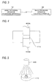
- the explanation as to the sealing and coating will be made later with reference to Figs. 4 and 5 .
- the imaging of an image will be explained by using Fig. 8 .
- the obtaining of an image includes the reading of an image using a scanner or a camera etc. and the reading of an image stored in a hard disk (contained in the image processing apparatus and coupled via a network, for example), for example.
- the reference image extraction module 120 is coupled to the image acquisition module 110, the reference image peripheral density extraction module 130 and the peculiar feature data extraction module 170.
- the reference image extraction module 120 extracts a partial image of the seal within the image obtained by the image acquisition module 110.
- an image at a predetermined position within the image may be extracted, an image at a predetermined position of the target object may be extracted, or an image having a predetermined feature may be extracted.
- the predetermined feature may be a portion where the entire length of a continuous line within the seal has a predetermined value or more and a portion configured by a curved line thereof has a predetermined length or more.
- a partial image of the seal located at the curved face of the target object may be extracted.
- the target object entirely has a curved face like a tablet
- the partial image of a seal at a portion other than the center portion of the target object may be extracted.
- the determination whether or not the target object is a three-dimensional object may be performed by using a sensor for detecting a three-dimensional shape, for example.
- a value representing a three-dimensional object is set to a parameter representing whether or not the target object is a three-dimensional object, whereby the determination may be made in accordance with the parameter.
- the partial image of the seal may be extracted in accordance with the pattern matching with an image having the aforesaid features.
- the partial image of the seal may be extracted n accordance with the coincident rate in a feature space. For example, in order to extract these features, the length of a line within the seal is extracted to determine whether or not the extracted line is a curved line, and the length of the portion configured by the curved line is extracted. Then, it is determined whether or not these features satisfy the predetermined condition (for example, a predetermined value or more).
- the partial image of the seal will be explained later with reference to Fig. 9 .
- the partial image of the seal to be extracted will also be called as a reference image.
- the reference image provides a reference position for extracting peculiar feature data by the peculiar feature data extraction module 170.
- the partial image represents a part of the image with respect to the entire image of the object, and hence may be an image including the entirety of the seal or, of course, may be an image of the part of the seal.
- the reference image peripheral density extraction module 130 is coupled to the reference image extraction module 120 and the feature data conversion module 140.
- the reference image peripheral density extraction module 130 extracts the density of the partial image of the seal extracted by the reference image extraction module 120.
- the "density of the partial image of the seal” may be the density of only the partial image of the seal, the density of the image of the seal portion and the peripheral portion thereof, or the density calculated by using these densities in accordance with a predetermined calculation method. The density of the partial image of the seal will be explained later with reference to Figs. 12 to 15 .
- the feature data conversion module 140 is coupled to the reference image peripheral density extraction module 130 and the feature data/peripheral data register module 150.
- the feature data conversion module 140 converts a sequence of the densities extracted by the reference image peripheral density extraction module 130 into the feature of the partial image of the seal.
- This feature may be any kind of feature so long as it represents the feature of the partial image of the seal. The concrete example of the feature will be explained later with reference to Fig. 16 .
- the feature data/peripheral data register module 150 is coupled to the feature data conversion module 140 and the feature data/peripheral data storage module 160.
- the feature data/peripheral data register module 150 registers the feature thus converted by the feature data conversion module 140 and the density extracted by the reference image peripheral density extraction module 130 in a corresponding manner in the feature data/peripheral data storage module 160. That is, the registration is performed so that the feature is retrieved from the feature data/peripheral data storage module 160 and the density corresponding to the feature can be extracted.
- a single density single density sequence
- a plurality of densities may correspond to the single feature.
- the feature data/peripheral data storage module 160 is coupled to the feature data/peripheral data register module 150.
- the feature data/peripheral data storage module 160 stores the feature converted by the feature data conversion module 140 and the density extracted by the reference image peripheral density extraction module 130 in the corresponding manner.
- the peculiar feature data extraction module 170 is coupled to the reference image extraction module 120 and the peculiar feature data register module 180.
- the peculiar feature data extraction module 170 extracts an image at the predetermined position from the position of the extracted partial image of the seal.
- the "predetermined position from the position of the extracted partial image of the seal” corresponds, for example, to a rectangle etc. located at the position with predetermined distances respectively in the X-coordinate direction and the Y-coordinate direction from the position of the left top (may be right top, right bottom, left bottom or center etc.) of the circumscribed rectangle of the partial image of the seal.
- the "predetermined position” may be within the partial image of the seal.
- the image at this position is also called peculiar feature data.
- the peculiar feature data register module 180 is coupled to the peculiar feature data extraction module 170 and the peculiar feature data storage module 190.
- the peculiar feature data register module 180 registers the image extracted by the peculiar feature data extraction module 170 in the peculiar feature data storage module 190. That is, the image may be registered so that the image within the object can be extracted from the peculiar feature data storage module 190.
- the image stored in the peculiar feature data storage module 190 is associated with an object identifier (tablet number etc. when the object is a tablet) for identifying the object which image is obtained by the image acquisition module 110.
- an object identifier tablet number etc. when the object is a tablet
- the peculiar feature data storage module 190 is coupled to the peculiar feature data register module 180.
- the peculiar feature data storage module 190 stores the image extracted by the peculiar feature data extraction module 170.
- Fig. 2 is a schematic diagram showing the configuration of modules as to an example of the configuration of an image processing apparatus (collating apparatus) according to the exemplary embodiment.
- the image processing apparatus (collating apparatus) collates the images of the objects registered by the image processing apparatus (registering apparatus) 100 shown in Fig. 1 exemplarily with the image of the target object. As shown in an example of Fig.
- the image processing apparatus (collating apparatus) 200 includes an image acquisition module 210, a reference image extraction module 220, a reference image peripheral density extraction module 230, a feature data conversion module 240, a collation (A) module 250, a feature data/peripheral data storage module 160, a peculiar feature data extraction module 270, a collation (B) module 280, a peculiar feature data storage module 190 and an output module 290.
- this image processing apparatus may be configured not to include any of the peculiar feature data extraction module 270, the collation (B) module 280 and the output module 290.
- portions identical or similar to those of the image processing apparatus (registering apparatus) 100 shown in Fig. 1 exemplarily are referred to by the common symbols, with explanation thereof being omitted.
- the image acquisition module 210 is coupled to the reference image extraction module 220.
- the image acquisition module 210 obtains an image of an object having a seal impressed on the face thereof and also having a film formed or laminated thereon.
- the object is equivalent to that explained in relation to the image acquisition module 110 of the image processing apparatus (registering apparatus) 100 shown in Fig. 1 exemplarily. However, this object is an object required for the collation.
- the "object" of the "image of the object” obtained by the image acquisition module 210 is a tablet distributed in the market which is required for the collation in order to determine the authenticity etc.
- the image acquisition module 210 may be arranged to obtain a plurality of images by changing the inclination of the object.
- the object may be imaged for plural times by changing the inclination of the object, the angle of an imaging apparatus and the illumination angle etc.
- This is to set the imaging condition of this image acquisition module so as to be same as that of the image acquisition module 110 of the image processing apparatus (registering apparatus) 100. That is, as to the object such as a tablet which easily inclines, since it is impossible to control the inclination of the object at the time of registration (in particular, at the time of registration in the case of the manufacturing process), the imaging of the object is generally performed only once.
- the imaging in the image acquisition module 210 of the image processing apparatus (collating apparatus) 200 is not necessarily same as the imaging at the time of registration.
- the lenses, the image sensor of the imaging apparatus, the feature extracted from the obtained image may differ depending on the inclination with respect to the center shaft at the time of obtaining the image. Since the inclination with respect to the center shaft at the time of registration is unclear, the modules 210 of the image processing apparatus (collating apparatus) 200 obtains the images of the object for plural times with different inclination conditions with respect to the center shaft.
- the image acquisition module 210 may generate a single image from the imaged plural images. For example, a single image may be selected from the imaged plural images or a single image may be obtained by averaging the imaged plural images.
- each of the reference image extraction module 220, the reference image peripheral density extraction module 230, the feature data conversion module 240 and the collation (A) module 250 may perform the processing of plural images obtained by the image acquisition module 210.
- the reference image extraction module 220 extracts plural partial images from the plural images and the reference image peripheral density extraction module 230 extracts the densities of the plural partial images.
- the collation (A) module 250 performs the collation between the plural densities extracted from the feature data/peripheral data storage module 160 and the plural densities extracted from the reference image peripheral density extraction module 230.
- the collation (A) module 250 performs the collation between the plural densities extracted from the feature data/peripheral data storage module 160 and the plural densities extracted from the reference image peripheral density extraction module 230.
- the reference image extraction module 220 is coupled to the image acquisition module 210 and the reference image peripheral density extraction module 230.
- the reference image extraction module 220 extracts the partial image of the seal within an obtained image. This method of extracting the partial image of the seal is equivalent to that explained above in relation to the reference image extraction module 120 of the image processing apparatus (registering apparatus) 100 shown in Fig. 1 exemplarily. The partial image of the seal will be explained later with reference to Fig. 9 .
- the reference image peripheral density extraction module 230 is coupled to the reference image extraction module 220 and the feature data conversion module 240.
- the reference image peripheral density extraction module 230 extracts the density of the partial image of the seal extracted from the reference image extraction module 220. This method of extracting the density of the partial image of the seal is equivalent to that explained above in relation to the reference image peripheral density extraction module 130 of the image processing apparatus (registering apparatus) 100 shown in Fig. 1 exemplarily. The density of the partial image of the seal will be explained later with reference to Figs. 12 to 15 .
- the feature data conversion module 240 is coupled to the reference image peripheral density extraction module 230 and the collation (A) module 250.
- the feature data conversion module 240 converts a sequence of the densities extracted by the reference image peripheral density extraction module 230 into the feature of the partial image of the seal.
- This feature is equivalent to that explained above in relation to the feature data conversion module 140 of the image processing apparatus (registering apparatus) 100 shown in Fig. 1 exemplarily. The concrete example of the feature will be explained later with reference to Fig. 16 .
- the collation (A) module 250 is coupled to the feature data conversion module 240, the feature data/peripheral data storage module 160 and the peculiar feature data extraction module 270.
- the collation (A) module 250 extracts, from the feature data/peripheral data storage module 160, the density corresponding to the feature obtained by the conversion processing of the feature data conversion module 240 and collates the extracted density with the density extracted by the reference image peripheral density extraction module 230. This collation may be the collation for determining the authenticity etc.
- the collation (B) module 280 performs the collation for determining the authenticity etc.
- the collation (A) module extracts a collation candidate for the collation by the collation (B) module 280.
- the feature data/peripheral data storage module 160 is coupled to the collation (A) module 250.
- the feature data/peripheral data register module 150 of the image processing apparatus (registering apparatus) 100 registers the feature of the partial image of the seal as a reference and the density of the partial image of the seal in a corresponding manner in the feature data/peripheral data storage module 160.
- the peculiar feature data extraction module 270 is coupled to the collation (A) module 250 and the collation (B) module 280.
- the peculiar feature data extraction module 270 extracts an image located at a predetermined position from the position of the partial image of the seal extracted by the reference image extraction module 220.
- the predetermined position from the position of the partial image of the seal is equivalent to that explained in relation to the peculiar feature data extraction module 170 of the image processing apparatus (registering apparatus) 100 shown in Fig. 1 exemplarily.
- the collation (B) module 280 is coupled to the peculiar feature data extraction module 270, the peculiar feature data storage module 190 and the output module 290.
- the collation (B) module 280 extracts an image from the peculiar feature data storage module 190 and collates the extracted image with the image extracted by the peculiar feature data extraction module 270.
- the collation processing of the collation (B) module 280 will be explained later.
- the peculiar feature data storage module 190 is coupled to the collation (B) module 280.
- the peculiar feature data storage module 190 registers the images extracted by the peculiar feature data extraction module 170 of the image processing apparatus (registering apparatus) 100 shown in Fig. 1 exemplarily.
- the output module 290 is coupled to the collation (B) module 280.
- the output module 290 outputs the collation result obtained by the collation (B) module 280 (or the collation (A) module 250).
- the collation result is the determination result of the authenticity (determination result as to whether or not manufactured by a target factory or a manufacturing apparatus etc.), for example.
- the outputting of the collation result is to print out by a printing apparatus such as a printer, to display on a display apparatus such as a display, to store in a storage medium such as a memory card or to send to other information processing apparatus, for example.
- Fig. 3 is an explanatory diagram showing an example of the system configuration in a case of realizing the exemplary embodiment.
- the image processing apparatus (registering apparatus) 100 shown in Fig. 1 exemplarily and the image processing apparatus (collating apparatus) 200 shown in Fig. 2 exemplarily are coupled via a communication line.
- the image processing apparatus (registering apparatus) 100 is installed in a factory etc. manufacturing tablets and registers the images of manufactured tablets.
- the image processing apparatus (collating apparatus) 200 performs the collation processing in order to determine whether or not each of tablets distributed in the market is manufactured by the factory etc.
- the respective information stored in the feature data/peripheral data storage module 160 and the peculiar feature data storage module 190 of the image processing apparatus (registering apparatus) 100 is transferred to the feature data/peripheral data storage module 160 and the peculiar feature data storage module 190 of the image processing apparatus (collating apparatus) 200, respectively.
- the image processing apparatus (registering apparatus) 100 may register the respective information into the feature data/peripheral data storage module 160 and the peculiar feature data storage module 190 of the image processing apparatus (collating apparatus) 200 via the communication line.
- the image processing apparatus (collating apparatus) 200 may perform the collation processing by using the feature data/peripheral data storage module 160 and peculiar feature data storage module 190 of the image processing apparatus (registering apparatus) 100 via the communication line.
- both the feature data/peripheral data storage module 160 and the peculiar feature data storage module 190 may be disposed in an image processing apparatus (server etc.) other than the image processing apparatus (registering apparatus) 100 and the image processing apparatus (collating apparatus) 200 and each of the image processing apparatus (registering apparatus) 100 and the image processing apparatus (collating apparatus) 200 may access these modules via the communication lines.
- Fig. 6 is a flowchart showing an example of the processing performed by the image processing apparatus (registering apparatus) 100 according to the exemplary embodiment.
- step S602 the image acquisition module 110 obtains an image of the tablet having been sealed and coated.
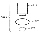
- Fig. 8 is an explanatory diagram showing an example of the processing by the image acquisition module 110.
- an imaging apparatus (digital camera) 810 images a tablet 800 illuminated by an illumination 820.
- the illumination 820 is desirably arranged to illuminate light uniformly toward the entire peripheral direction of the tablet so as not to form any shade portion.
- the reference image extraction module 120 extracts the reference image.
- Fig. 9 is explanatory diagrams showing examples of the reference image as the partial image of the tablet. Each of these drawings shows a case where the character image of "C", for example, is extracted from the imaged image of the tablet as the reference image from the seal formed by characters and symbols.
- Fig. 9A to 9I show the cases where the reference images "C" are extracted from nine tablets, respectively. It is clear from these drawings that irregular deformation appears in the image of "C”.
- This reference image "C” is extracted in a manner, for example, that the reference image "C” is specified and extracted according to the pattern patching using a standard image shown in Fig. 10 exemplarily. The reference image thus extracted may be subjected to the image processing.
- the image shown in Fig. 11A is the extracted reference image
- the image shown in Fig. 11B is the reference image subjected to a rotating processing.
- the image processing may be, for example, a parallel moving processing, an affine transformation processing such as an expansion/contraction processing, a noise removing processing or a density conversion processing instead of the rotating processing.
- the standard image is an image for extracting the reference image from the image of an object.
- the standard image may be generated by imaging the seal of the stamper 420A or 420B or by averaging a plurality of reference images.
- the reference image peripheral density extraction module 130 extracts the peripheral density of the reference image.
- Fig. 12 is an explanatory diagram showing an example of the extraction of the peripheral density of the reference image which is the partial image of the seal.
- Fig. 12A shows an example of the reference image
- Fig. 12B shows an example of an image obtained by superimposing the standard image shown in Fig. 10 exemplarily on the reference image.
- the density of the reference image is extracted based on pixels thereof at positions of the respective black pixels of the standard image. For example, as shown in the example of Fig.
- a sequence of statistical values (average value, mode value, center value etc., for example) of the densities of peripheral nine pixels around the position of each of the black pixels (83 pixels such as standard pixels 1310, 1320, 1330 in this case) of the standard image is set as the density of the reference image.
- the peripheral nine pixels are peripheral pixels 1315 including the pixel of the reference image located at the position of the standard pixel 1310, peripheral pixels 1325 including the pixel of the reference image located at the position of the standard pixel 1320, peripheral pixels 1335 including the pixel of the reference image located at the position of the standard pixel 1330, etc.
- the density of the reference image may be the density obtained based on peripheral twenty-five pixels etc.
- the density is extracted in a manner that the standard image is superimposed on the reference image and the densities of the pixels at the superimposed positions are used.
- the exemplary embodiment is not limited thereto and it is sufficient to extract the density based on the densities within the reference image.
- the density may be extracted based on the densities of all pixels within the reference image or based on the densities of pixels within the reference image each having a predetermined density or more.
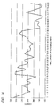
- Fig. 14 is an explanatory diagram showing an example of peripheral density sequence data.
- This figure is a graph (ordinate: density, abscissa: pixel order of reference image) showing the peripheral density sequence of the reference image shown in Fig. 12B exemplarily and this figure shows the densities of 83 pixels.
- the pixel order of reference image is a predetermined order.
- the pixel order may be determined in a manner that, for example, the rectangle (upper end pixel of "C") shown in Fig. 12B exemplarily is determined as the first pixel and the numbers are determined sequentially along the drawing order to the 83-th pixel.
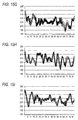
- Fig. 15 is explanatory diagrams showing an example of peripheral density sequence data of the reference images shown in Figs. 9A to 9I exemplarily.
- each of the reference images represents the same character "C”
- these graphs of the respective reference images represent different configurations since the image of the character is deformed.
- Each of the graphs is formed by plural lines since the object is imaged plural times (ten times in this example) under different conditions and obtained densities are plotted in the graph. This means that the difference of the shape of the graph is not so large among the respective imaging operations.
- Fig. 16 is an explanatory diagram showing an example of a peripheral density data sequence 1600, a converted data sequence 1610 and feature data.
- the feature data shown in Fig. 16 is obtained in a manner that the peripheral density data sequence 1600 is converted into the converted data sequence 1610 formed by frequency components (large frequency components) of predetermined value or more of the peripheral density data sequence and the converted data sequence 1610 is subjected to a digitizing processing.
- the digitizing processing is performed in a manner that the reduction and the increase are respectively represented by "0" and "1", and "0" or "1” is repeated for plural times (two times n this case) when the length of the reduction or the increase is a predetermined value or more.
- a section 1622 is “00"
- a section 1624 is “1”
- a section 1626 is “00”
- a section 1628 is “1”
- a section 1630 is “0”
- a section 1632 is “1”
- a section 1634 is “0”
- a section 1636 is “1”.
- the peripheral density data sequence 1600 shown in Fig. 16 exemplarily is converted into the feature data "0010010101”.
- this conversion method there may arise a case that different pieces of peripheral density sequence data are converted into the same feature data. This means that the peripheral density sequence data is classified by the feature data.
- a method other than this conversion method may be employed so long as the peripheral density sequence data can be converted into the feature data.
- step S610 the feature data/peripheral data register module 150 registers the feature data and the peripheral density sequence data into the feature data/peripheral data storage module 160.
- the feature data "0010010101" and is the peripheral density data sequence 1600 are registered in the feature data/peripheral data storage module 160 in a corresponding manner.
- step S612 the peculiar feature data extraction module 170 extracts the peripheral feature data. That is, an image at the predetermined position is extracted from the image of the tablet with reference to the position of the reference image.
- step S614 the peculiar feature data register module 180 registers the peripheral feature data into the peculiar feature data storage module 190.
- step S612 and step S614 each processing of step S612 and step S614 is not performed.
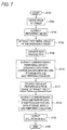
- Fig. 7 is a flowchart showing an example of the processing performed by the image processing apparatus (collating apparatus) 200 according to the exemplary embodiment.
- step S702 the image acquisition module 210 obtains an image of the tablet.
- This step performs the processing equivalent to that of step S602 shown in Fig. 6 exemplarily.
- the image of a target tablet is the image of a table as a reference (image of the tablet having been manufactured in a factory etc.) in the example of Fig. 6
- the image of a target tablet is the image of a tablet as a subject for collation in the example of Fig. 7 .
- step S704 the reference image extraction module 220 extracts the reference image. This step performs the processing equivalent to that of step S604 shown in Fig. 6 exemplarily.
- step S706 the reference image peripheral density extraction module 230 extracts the peripheral density of the reference image. This step performs the processing equivalent to that of step S606 shown in Fig. 6 exemplarily.
- step S708 the feature data conversion module 240 converts the extracted peripheral density into the feature data. This step performs the processing equivalent to that of step S608 shown in Fig. 6 exemplarily.
- step S710 the collation (A) module 250 extracts corresponding peripheral density sequence data from the feature data/peripheral data storage module 160 and performs the collation. That is, the collation (A) module extracts the peripheral density sequence data corresponding to the feature data from the feature data/peripheral data storage module 160 and collates with the peripheral density sequence data extracted in step S706. For example, the collation is performed by using the normalized correlation method. To be concrete, in the case where the feature data "0010010101" is obtained in step S708, the peripheral density sequence data (see the graph exemplarity shown in Fig.
- step S716 When the respective data does not coincide to each other as the result of the collation process (when it is determined to be a fake), the process proceeds to step S716 without performing steps S712 and S714.
- step S712 the module 712 extracts the peculiar feature data from the image of a target tablet. This step performs the processing equivalent to that of step S612 shown in Fig. 6 exemplarily.
- step S714 the collation (B) module 280 extracts corresponding peculiar feature data from the peculiar feature data storage module 190 and performs the collation. For example, an authenticity determining method explained later is employed.
- step S716 the output module 290 outputs the collation result.
- step S712 and step S714 are not performed.
- the collation method in the collation (B) module 280 may be the following authenticity determining method.
- An authenticity determination method for determining the authenticity of objects which readable peculiar feature having randomness is distributed along the face thereof is characterized by including the steps of:
- the authenticity determination method described in ⁇ A1> wherein the feature of the object can be read optically, and the reference data and the collation data is image data obtained by irradiating light on the true object and the object to be determined and by reading reflection light or transmission light.
- a tone value range which is estimated to contain a noise component, is set based on the distribution of the tone values with respect to at least one of the reference data and the collation data, and the correlation values are calculated after removing the data belonging to the tone value range thus set.
- the authenticity determination method described in ⁇ A5> wherein the reference data is obtained by reading, from a predetermined medium, reference data which is obtained by optically reading the feature of the true object and recorded in the predetermined medium, then the tone value range, which is estimated to contain a noise component with respect to the reference data, is set based on the distribution of the tone values of the reference data thus obtained, and the correlation values are calculated after removing the data belonging to the tone value range thus set from the reference data.
- the authenticity determination method described in ⁇ A5> or ⁇ A6> wherein as the range estimated to contain the noise component, there is set a range from the maximum or minimum value of the tone value to a value where an accumulation frequency reaches a predetermined value or a range where the tone value is AVE + n ⁇ or more or the tone value is AVE - n ⁇ or less supposing that the average value of the tone values is AVE, the standard deviation of the distribution of the tone values is ⁇ and predetermined value is n.
- FIG. 19 An example of the hardware configuration of the image processing apparatus (registering apparatus) and the image processing apparatus (collating apparatus) according to the exemplary embodiment will be explained with reference to Fig. 19 .
- the configuration shown in Fig. 19 is configured by a personal computer (PC) etc., for example, and shows an example of the hardware configuration including a data reading portion 1917 such as a scanner and a data output portion 1918 such as a printer.
- PC personal computer
- a CPU (Central Processing Unit) 1901 is a control portion which executes the processing according to the computer program describing the execution sequences of the respective modules explained in the aforesaid exemplary embodiment such as the reference image extraction module 120, the reference image peripheral density extraction module 130, the feature data conversion module 140, the feature data/peripheral data register module 150, the peculiar feature data extraction module 170, the peculiar feature data register module 180, the reference image extraction module 220, the reference image peripheral density extraction module 230, the feature data conversion module 240, the collation (A) module 250, the peculiar feature data extraction module 270, the collation (B) module 280, the output module 290.
- the reference image extraction module 120 the reference image peripheral density extraction module 130, the feature data conversion module 140, the feature data/peripheral data register module 150, the peculiar feature data extraction module 170, the peculiar feature data register module 180, the reference image extraction module 220, the reference image peripheral density extraction module 230, the feature data conversion module 240, the collation (A) module 250, the peculiar feature data extraction
- a ROM (Read Only Memory) 1902 stores the programs and operation parameters etc. used by the CPU 1901.
- a RAM (Random Access Memory) 1903 stores programs used at the time of the execution of the CPU 1901 and parameters etc. which suitably change at the time of the execution. These constituent elements are mutually coupled via a host bus 1904 configured by a CPU bus etc.
- the host bus 1904 is coupled to an external bus 1906 such as a PCI (Peripheral Component Interconnect/Interface) bus via a bridge 1905.
- PCI Peripheral Component Interconnect/Interface
- Each of a key board 1908 and a pointing device 1909 such as a mouse is an input device operated by a user.
- a display 1910 is a liquid crystal device or a CRT (Cathode Ray Tube) and displays various kinds of information as texts and image information.
- An HDD (Hard Disk Drive) 1911 contains hard disks and records and reproduces the programs and information executed by the CPU 1901 buy driving the hard disks.
- the hard disks store the target images, feature data, peripheral data, peculiar feature data etc. and also store various kinds of computer programs such as various kinds of data processing programs.
- a driver 1912 reads data or program stored in a removable recording medium 1913 such as a magnetic disk, an optical disk, an magneto-optical disk or a semiconductor memory attached thereto and supplies the data or the program to the RAM 1903 which is coupled via an interface 1907, the external bus 1906, the bridge 1905 and the host bus 1904.
- the removable recording medium 1913 can also be used as a data recording area equivalent to the hard disk.
- a coupling port 1914 is a port for connecting an external coupling device 1915 and has a coupling portion such as USB, IEEE1394.
- the coupling port 1914 is coupled to the CPU 1901 etc. via the interface 1907, the external bus 1906, the bridge 1905, the host bus 1904 etc.
- a communication portion 1916 is coupled to the network and executes a data communication processing with the external unit.
- the data reading portion 1917 is configured by a scanner, for example, and executes a reading processing of documents.
- the data output portion 1918 is configured by a printer, for example, and executes an output processing of document data.
- Fig. 19 shows an example of the hardware configuration of the image processing apparatus (registering apparatus) and the image processing apparatus (collating apparatus) and the configuration of the exemplary embodiment is not limited thereto, and hence the configuration of the exemplary embodiment may be any one which can execute the respective modules explained in the aforesaid exemplary embodiment.
- a part of the modules may be configured by a dedicated hardware (for example, an ASIC (Application Specific Integrated Circuit) etc.).
- ASIC Application Specific Integrated Circuit
- Apart of the modules may be provided within an external system and connected via a communication line.
- a plural sets of the system shown in Fig. 19 may be provided and coupled to each other via a communication line so as to operate in a cooperating manner.
- the hardware configuration may be incorporated into a copy machine, a facsimile machine, a scanner, a printer, a complex machine (an image processing apparatus having the function of at least two of a scanner, a printer, a copy machine, a facsimile machine etc.).
- the explanation is made as to the case where the object is mainly a tablet as an example, the object may be one other than a tablet.
- the aforesaid exemplary embodiments may be combined (for example, the module within one of the exemplary embodiments is added into the other exemplary embodiment, or the modules of the exemplary embodiments are exchanged therebetween). Further, the technique explained in the background technique may be employed in the processing contents of the respective modules.
- the programs explained above may be provided in a manner of being stored in a recording medium or via a communication means.
- the invention of the program may be understood as the invention of "a computer readable recording medium in which the programs is recorded”.
- the "computer readable recording medium in which the programs is recorded” is a recording medium capable of being read by a computer used for installing, executing and distributing the programs, for example.
- the recording medium may be, for example, a digital versatile disk (DVD) such as "DVD-R, DVD-RW, DVD-RAM etc.” which is the standard formulated in the DVD forum or "DVD+R, DVD+RW etc.” which is the standard formulated in the DVD+RW forum, a compact disk (CD) such as a read only memory (CD-ROM), a CD recordable (CD-R), a CD rewritable (CD-RW), a blue-ray disk (trademark), a magneto-optical disk (MO), a flexible disk (FD), a magnetic tape, a hard disk, a read only memory (ROM), an electrically erasable programmable read-only memory (EEPROM: trademark), a flash memory, a random access memory (RAM).
- DVD digital versatile disk
- CD-ROM read only memory
- CD-R CD recordable
- CD-RW CD rewritable
- a blue-ray disk trademark
- MO magneto-optical disk
- FD flexible
- the programs or a part thereof may be recorded and stored in the recording medium and may be distributed, for example. Further, the programs or a part thereof may be transmitted via the transmission medium such as the cable network or the wireless communication network or the combination thereof used in the local area network (LAN), the metropolitan area network (MAN), the wide area network (WAN), the internet, the intranet, the extranet etc. Alternatively, the programs or a part thereof may be transmitted by being superimposed on the carrier wave.
- the transmission medium such as the cable network or the wireless communication network or the combination thereof used in the local area network (LAN), the metropolitan area network (MAN), the wide area network (WAN), the internet, the intranet, the extranet etc.
- the programs or a part thereof may be transmitted by being superimposed on the carrier wave.
- one of the programs may be a part of another program and may be recorded in the recording medium together with another program. Further, the programs may be recorded into a plurality of the recording mediums in a divided manner. Furthermore, the programs may be recorded in any mode such as the compression or encryption so long as the programs can be restored.
Landscapes
- Engineering & Computer Science (AREA)
- Physics & Mathematics (AREA)
- General Physics & Mathematics (AREA)
- Multimedia (AREA)
- Theoretical Computer Science (AREA)
- Image Analysis (AREA)
- Investigating Materials By The Use Of Optical Means Adapted For Particular Applications (AREA)
- Character Input (AREA)
- Image Processing (AREA)
- Collating Specific Patterns (AREA)
- Image Input (AREA)
Applications Claiming Priority (1)
| Application Number | Priority Date | Filing Date | Title |
|---|---|---|---|
| JP2010257515A JP5703707B2 (ja) | 2010-11-18 | 2010-11-18 | 画像処理システム、画像処理装置及び画像処理プログラム |
Publications (2)
| Publication Number | Publication Date |
|---|---|
| EP2455890A2 true EP2455890A2 (de) | 2012-05-23 |
| EP2455890A3 EP2455890A3 (de) | 2015-04-22 |
Family
ID=45375126
Family Applications (1)
| Application Number | Title | Priority Date | Filing Date |
|---|---|---|---|
| EP20110164956 Ceased EP2455890A3 (de) | 2010-11-18 | 2011-05-05 | Bildverarbeitungssystem, Bildverarbeitungsvorrichtung und Bildverarbeitungsprogramm |
Country Status (4)
| Country | Link |
|---|---|
| US (1) | US8761508B2 (de) |
| EP (1) | EP2455890A3 (de) |
| JP (1) | JP5703707B2 (de) |
| CN (1) | CN102467662B (de) |
Cited By (1)
| Publication number | Priority date | Publication date | Assignee | Title |
|---|---|---|---|---|
| JP2014092474A (ja) * | 2012-11-05 | 2014-05-19 | Toyota Motor Corp | 刻印方法および刻印装置 |
Families Citing this family (9)
| Publication number | Priority date | Publication date | Assignee | Title |
|---|---|---|---|---|
| US9842285B2 (en) * | 2011-07-29 | 2017-12-12 | Nec Corporation | Collation/retrieval system, collation/retrieval server, image feature extraction apparatus, collation/retrieval method, and program |
| JP5977703B2 (ja) * | 2013-03-29 | 2016-08-24 | 富士フイルム株式会社 | 条件再現方法,ならびに画像照合装置およびその動作制御方法 |
| US9141872B2 (en) * | 2013-09-11 | 2015-09-22 | Digitalglobe, Inc. | Automated and scalable object and feature extraction from imagery |
| CN103927516A (zh) * | 2014-04-09 | 2014-07-16 | 海南大学 | 基于数字图像处理的海水珍珠鉴别系统 |
| JP6894977B2 (ja) * | 2017-08-22 | 2021-06-30 | 富士フイルム富山化学株式会社 | 薬剤検査支援装置、薬剤検査支援方法、薬剤識別装置、薬剤識別方法及びプログラム、記録媒体 |
| CN108596197B (zh) * | 2018-05-15 | 2020-08-25 | 汉王科技股份有限公司 | 一种印章匹配方法及装置 |
| US11983864B2 (en) | 2018-08-23 | 2024-05-14 | Nec Corporation | Object matching device |
| CN111914283B (zh) * | 2020-08-20 | 2024-03-26 | 释空(上海)品牌策划有限公司 | 一种基于大数据区块链的文件电子签章算法 |
| WO2022154093A1 (ja) * | 2021-01-14 | 2022-07-21 | 富士フイルム株式会社 | 真正性照合システム及び真正性照合方法 |
Citations (4)
| Publication number | Priority date | Publication date | Assignee | Title |
|---|---|---|---|---|
| JP2004153405A (ja) | 2002-10-29 | 2004-05-27 | Fuji Xerox Co Ltd | 書類確認方法及び装置 |
| JP2006164180A (ja) | 2004-12-10 | 2006-06-22 | Fuji Xerox Co Ltd | 固体識別装置及び方法 |
| JP2008509498A (ja) | 2004-08-13 | 2008-03-27 | インゲニア・テクノロジー・リミテッド | データベースを使用した物品の信頼性認証 |
| JP4103826B2 (ja) | 2003-06-24 | 2008-06-18 | 富士ゼロックス株式会社 | 真偽判定方法、装置及びプログラム |
Family Cites Families (9)
| Publication number | Priority date | Publication date | Assignee | Title |
|---|---|---|---|---|
| JPH1083456A (ja) * | 1996-09-09 | 1998-03-31 | Ntn Corp | 文字パターンの位置検出方法 |
| SG75190A1 (en) * | 1998-12-14 | 2000-09-19 | Canon Kk | Image processing method and apparatus image processing system and storage medium |
| JP3344995B2 (ja) * | 2000-09-22 | 2002-11-18 | 東芝アイティー・ソリューション株式会社 | 錠剤表面検査装置 |
| CZ2005209A3 (cs) * | 2002-09-10 | 2005-12-14 | Ivi Smart Technologies, Inc. | Bezpečné biometrické ověření identity |
| US7489807B2 (en) * | 2003-08-07 | 2009-02-10 | Kyungtae Hwang | Statistical quality assessment of fingerprints |
| US20050063562A1 (en) * | 2003-08-07 | 2005-03-24 | Brunk Hugh L. | Conveying fingerprint minutiae with digital watermarks |
| CA2600938A1 (en) * | 2004-03-24 | 2005-10-06 | Andre Hoffmann | Identification, verification, and recognition method and system |
| EP1989657A4 (de) * | 2006-02-10 | 2010-10-20 | Parallel Synthesis Technologie | Authentifizierung und fälschungssichere verfahren und vorrichtungen |
| IL185130A0 (en) * | 2007-08-08 | 2008-01-06 | Semi Conductor Devices An Elbi | Thermal based system and method for detecting counterfeit drugs |
-
2010
- 2010-11-18 JP JP2010257515A patent/JP5703707B2/ja not_active Expired - Fee Related
-
2011
- 2011-04-26 US US13/094,440 patent/US8761508B2/en not_active Expired - Fee Related
- 2011-05-05 EP EP20110164956 patent/EP2455890A3/de not_active Ceased
- 2011-05-18 CN CN201110129212.6A patent/CN102467662B/zh active Active
Patent Citations (4)
| Publication number | Priority date | Publication date | Assignee | Title |
|---|---|---|---|---|
| JP2004153405A (ja) | 2002-10-29 | 2004-05-27 | Fuji Xerox Co Ltd | 書類確認方法及び装置 |
| JP4103826B2 (ja) | 2003-06-24 | 2008-06-18 | 富士ゼロックス株式会社 | 真偽判定方法、装置及びプログラム |
| JP2008509498A (ja) | 2004-08-13 | 2008-03-27 | インゲニア・テクノロジー・リミテッド | データベースを使用した物品の信頼性認証 |
| JP2006164180A (ja) | 2004-12-10 | 2006-06-22 | Fuji Xerox Co Ltd | 固体識別装置及び方法 |
Non-Patent Citations (4)
| Title |
|---|
| "Image Processing for the Food Industry", 1 January 2000, ISBN: 978-981-0240-22-6, article R. D. DAVIES: "Image Processing for the Food Industry", pages: 180, XP055339442 * |
| HUSSEIN EL BUAESHI: "Classification of digitized curves represented by signatures and Fourier descriptors", MASTER THESIS, CONCORDIA UNIVERSITY, 1 January 1988 (1988-01-01), XP055339353, Retrieved from the Internet <URL:http://spectrum.library.concordia.ca/2716/1/ML44808.pdf> [retrieved on 20170126] * |
| RICHARD DEN HOLLANDER ET AL: "Logo recognition in video by line profile classification", PROCEEDINGS OF SPIE, vol. 5307, 22 December 2003 (2003-12-22), XP055132795, ISSN: 0277-786X, DOI: 10.1117/12.525025 * |
| TOMAS LOZANO-PEREZ: "Parsing Intensity Profiles", COMPUTER GRAPHICS AND IMAGE PROCESSING, VOLUME 6, ISSUE 1, 1 February 1977 (1977-02-01), pages 43 - 60, XP055339425, Retrieved from the Internet <URL:http://www.sciencedirect.com/science/article/pii/S0146664X77800038/pdf?md5=50e12565d4ec38e6618194a55d6215f9&pid=1-s2.0-S0146664X77800038-main.pdf> [retrieved on 20170126] * |
Cited By (1)
| Publication number | Priority date | Publication date | Assignee | Title |
|---|---|---|---|---|
| JP2014092474A (ja) * | 2012-11-05 | 2014-05-19 | Toyota Motor Corp | 刻印方法および刻印装置 |
Also Published As
| Publication number | Publication date |
|---|---|
| US20120128247A1 (en) | 2012-05-24 |
| US8761508B2 (en) | 2014-06-24 |
| CN102467662B (zh) | 2016-07-13 |
| JP5703707B2 (ja) | 2015-04-22 |
| JP2012108752A (ja) | 2012-06-07 |
| EP2455890A3 (de) | 2015-04-22 |
| CN102467662A (zh) | 2012-05-23 |
Similar Documents
| Publication | Publication Date | Title |
|---|---|---|
| EP2455890A2 (de) | Bildverarbeitungssystem, Bildverarbeitungsvorrichtung und Bildverarbeitungsprogramm | |
| US9088673B2 (en) | Image registration | |
| US20170287252A1 (en) | Counterfeit Document Detection System and Method | |
| US8520941B2 (en) | Method and system for document image classification | |
| US8810862B2 (en) | Paper medium information encrypting system, decrypting system, program and method | |
| CN108291876A (zh) | 用于检测产品的真实性的系统及方法 | |
| US11245811B2 (en) | Image processing apparatus, method and non-transitory computer readable medium storing image processing program | |
| US9247080B2 (en) | Information processing apparatus for acquiring a variation region between image data and read data | |
| US20120301033A1 (en) | Image processing apparatus, image processing method, and computer readable medium | |
| CN112308046A (zh) | 图像的文本区域定位方法、装置、服务器及可读存储介质 | |
| US6748102B2 (en) | Document alteration indicating system and method | |
| Mehta et al. | Near-duplicate detection for LCD screen acquired images using edge histogram descriptor | |
| US9858499B2 (en) | Image processor, non-transitory computer readable medium and object matching device | |
| US20130148912A1 (en) | Band-based patch selection with a dynamic grid | |
| US10834281B2 (en) | Document size detecting by matching between image of entire document and read size image | |
| US10318801B2 (en) | Image processing apparatus and non-transitory computer readable medium | |
| US8977044B2 (en) | Image processing apparatus for area separation of images, image processing method, and computer readable medium | |
| US20100189307A1 (en) | Image processing apparatus, image processing method and computer readable medium | |
| US8542922B2 (en) | Image processing apparatus, image processing method, and computer readable medium | |
| US8494272B2 (en) | Image processing device, image processing method, and computer readable medium for judging if images are matched | |
| JP4958868B2 (ja) | 文書特徴量抽出装置及び方法 | |
| JP4557875B2 (ja) | 画像処理方法及び装置 | |
| JP2011065311A (ja) | 画像処理装置及び画像処理プログラム | |
| JP2010049531A (ja) | 画像処理装置及び画像処理プログラム | |
| GB2630832A (en) | A method and system to record, register and verify copyright material |
Legal Events
| Date | Code | Title | Description |
|---|---|---|---|
| PUAI | Public reference made under article 153(3) epc to a published international application that has entered the european phase |
Free format text: ORIGINAL CODE: 0009012 |
|
| AK | Designated contracting states |
Kind code of ref document: A2 Designated state(s): AL AT BE BG CH CY CZ DE DK EE ES FI FR GB GR HR HU IE IS IT LI LT LU LV MC MK MT NL NO PL PT RO RS SE SI SK SM TR |
|
| AX | Request for extension of the european patent |
Extension state: BA ME |
|
| RIC1 | Information provided on ipc code assigned before grant |
Ipc: G06K 9/00 20060101AFI20141112BHEP |
|
| PUAL | Search report despatched |
Free format text: ORIGINAL CODE: 0009013 |
|
| AK | Designated contracting states |
Kind code of ref document: A3 Designated state(s): AL AT BE BG CH CY CZ DE DK EE ES FI FR GB GR HR HU IE IS IT LI LT LU LV MC MK MT NL NO PL PT RO RS SE SI SK SM TR |
|
| AX | Request for extension of the european patent |
Extension state: BA ME |
|
| RIC1 | Information provided on ipc code assigned before grant |
Ipc: G06K 9/00 20060101AFI20150317BHEP |
|
| 17P | Request for examination filed |
Effective date: 20151021 |
|
| RBV | Designated contracting states (corrected) |
Designated state(s): AL AT BE BG CH CY CZ DE DK EE ES FI FR GB GR HR HU IE IS IT LI LT LU LV MC MK MT NL NO PL PT RO RS SE SI SK SM TR |
|
| 17Q | First examination report despatched |
Effective date: 20160520 |
|
| STAA | Information on the status of an ep patent application or granted ep patent |
Free format text: STATUS: THE APPLICATION HAS BEEN REFUSED |
|
| 18R | Application refused |
Effective date: 20170919 |