EP2456072A2 - Interrupteur à commande au pied doté d'une détection de pied - Google Patents
Interrupteur à commande au pied doté d'une détection de pied Download PDFInfo
- Publication number
- EP2456072A2 EP2456072A2 EP11188366A EP11188366A EP2456072A2 EP 2456072 A2 EP2456072 A2 EP 2456072A2 EP 11188366 A EP11188366 A EP 11188366A EP 11188366 A EP11188366 A EP 11188366A EP 2456072 A2 EP2456072 A2 EP 2456072A2
- Authority
- EP
- European Patent Office
- Prior art keywords
- signal
- footswitch
- foot
- proximity sensor
- designed
- Prior art date
- Legal status (The legal status is an assumption and is not a legal conclusion. Google has not performed a legal analysis and makes no representation as to the accuracy of the status listed.)
- Withdrawn
Links
Images
Classifications
-
- H—ELECTRICITY
- H03—ELECTRONIC CIRCUITRY
- H03K—PULSE TECHNIQUE
- H03K17/00—Electronic switching or gating, i.e. not by contact-making and –breaking
- H03K17/94—Electronic switching or gating, i.e. not by contact-making and –breaking characterised by the way in which the control signals are generated
- H03K17/945—Proximity switches
-
- G—PHYSICS
- G06—COMPUTING OR CALCULATING; COUNTING
- G06F—ELECTRIC DIGITAL DATA PROCESSING
- G06F3/00—Input arrangements for transferring data to be processed into a form capable of being handled by the computer; Output arrangements for transferring data from processing unit to output unit, e.g. interface arrangements
- G06F3/01—Input arrangements or combined input and output arrangements for interaction between user and computer
- G06F3/03—Arrangements for converting the position or the displacement of a member into a coded form
- G06F3/033—Pointing devices displaced or positioned by the user, e.g. mice, trackballs, pens or joysticks; Accessories therefor
- G06F3/0334—Foot operated pointing devices
-
- H—ELECTRICITY
- H01—ELECTRIC ELEMENTS
- H01H—ELECTRIC SWITCHES; RELAYS; SELECTORS; EMERGENCY PROTECTIVE DEVICES
- H01H3/00—Mechanisms for operating contacts
- H01H3/02—Operating parts, i.e. for operating driving mechanism by a mechanical force external to the switch
- H01H3/14—Operating parts, i.e. for operating driving mechanism by a mechanical force external to the switch adapted for operation by a part of the human body other than the hand, e.g. by foot
-
- A—HUMAN NECESSITIES
- A61—MEDICAL OR VETERINARY SCIENCE; HYGIENE
- A61B—DIAGNOSIS; SURGERY; IDENTIFICATION
- A61B18/00—Surgical instruments, devices or methods for transferring non-mechanical forms of energy to or from the body
- A61B18/04—Surgical instruments, devices or methods for transferring non-mechanical forms of energy to or from the body by heating
- A61B18/12—Surgical instruments, devices or methods for transferring non-mechanical forms of energy to or from the body by heating by passing a current through the tissue to be heated, e.g. high-frequency current
- A61B18/1206—Generators therefor
-
- A—HUMAN NECESSITIES
- A61—MEDICAL OR VETERINARY SCIENCE; HYGIENE
- A61B—DIAGNOSIS; SURGERY; IDENTIFICATION
- A61B17/00—Surgical instruments, devices or methods
- A61B2017/00973—Surgical instruments, devices or methods pedal-operated
-
- H—ELECTRICITY
- H01—ELECTRIC ELEMENTS
- H01H—ELECTRIC SWITCHES; RELAYS; SELECTORS; EMERGENCY PROTECTIVE DEVICES
- H01H21/00—Switches operated by an operating part in the form of a pivotable member acted upon directly by a solid body, e.g. by a hand
- H01H21/02—Details
- H01H21/18—Movable parts; Contacts mounted thereon
- H01H21/22—Operating parts, e.g. handle
- H01H21/24—Operating parts, e.g. handle biased to return to normal position upon removal of operating force
- H01H21/26—Operating parts, e.g. handle biased to return to normal position upon removal of operating force adapted for operation by a part of the human body other than the hand, e.g. by foot
Definitions
- the invention relates to a foot switch according to the preamble of claim 1.
- Generic footswitches are known from medical technology. They are used there to devices such as high-frequency surgical equipment, patient beds, X-ray machines, laser devices and. Like., To control. Since the doctor does not have his hands free while working on the patient, he controls the medical devices with the help of the foot switches. This has the further advantage that the doctor's hands remain sterile and he touches only with the feet of possibly unsterile footswitch.
- the doctor In practice, the doctor often faces the problem of having to control several medical devices with the help of several foot switches.
- the work on the patient requires such a high degree of concentration from the doctor that he can not avert the gaze from the patient, he is only required to control the medical devices on the tactile stimuli, if he used different foot switches for driving the respectively different touches medical devices.
- Operating errors such as not turning on the desired medical device in time or accidentally switching on a medical device that is not wanted at the time can be dangerous for the patient Patients and / or for the doctor and possibly present medical assistants.
- the invention has for its object to improve a generic footswitch to the effect that this allows a clear identification of the respective footswitch before its operation without eye contact with the footswitch.
- the invention proposes to connect a proximity sensor to the actuating member of the foot switch, so that the presence of the foot is detected before the actual action can be triggered, which is provided upon actuation of the actuator, for example the control of the medical connected to this foot switch device. It is irrelevant whether the actuator has an analog or digital function.
- the footswitch has an electronic circuit operatively connected to the proximity sensor and having a signal output. If the sensory approach of the foot to the actuator is detected, the signal output is automatically controlled by means of the electronic circuit.
- a signal generator connected to this signal output then emits an optical and / or acoustic signal.
- this foot switch is actuated, and that further movement of the foot will result in activation of the actuator.
- the physician can be made aware of this already on the basis of this signaling before actuation of the respective actuating member, which footswitch he currently operates and which medical device will be controlled upon further actuation of the footswitch and upon actuation of the actuator. In this way, the user is warned against incorrect operation of the footswitch and accidental misuse of a medical device.
- the proximity sensor can be designed, for example, as a wire bow or the like, which is spring-loaded and movable, so that the signaling can be triggered by contact with such a bracket.
- the proximity sensor is designed as a non-contact sensor, so that the operation of the actual actuator for the user who is already used to certain footswitch, can remain unchanged and no additional tactile stimuli, mechanical resistances o. The like overcome.
- the proximity sensor can be configured as a light barrier, as a capacitive, infrared or ultrasonic sensor, so that in each case smooth surfaces of the foot switch are made possible, allowing a simple and reliable cleaning of the footswitch.
- the signal generator can be arranged within the foot switch itself and emit an acoustic signal.
- the signaling is ensured even if the user does not want to look at a display o. The like., And in particular not on the footswitch itself during his job.
- the signal generator is arranged outside the footswitch and can be connected to the signal output of the footswitch transfer-effective.
- a monitor provided on a medical device anyway may have a warning light o.
- a plurality of actuators of such a footswitch are each assigned a separate proximity sensor and an electronic circuit which evaluates the signals of the proximity sensors and a signal generator that either outputs different signals depending on the activated sensor, or each monitored actuator a separate, differently designed by other signal generator assigned.
- the actuation of each actuator of this footswitch is at least reliably monitored by the proximity sensors, so that then a signaling can be made, which is the same for all actuators of this footswitch and a distinction an actuation of another foot switch allows.
- the distinction of the individual actuators within the same footswitch can then be done in a conventional manner by different design of the individual actuators or by different design of the housing in the environment of the individual actuators, so that the already mentioned tactile Stimuli for the different actuators of the same footswitch are different and allow the user the required distinction.
- the actuator may be surrounded by so-called locking elements, so that the actuator is not accessible from any direction.
- there is a veritable approach corridor for the actuation of the actuator so that in this way the monitoring of the actuator with the aid of the proximity sensor can be carried out particularly reliably by having its detection range within the approaching corridor.
- a particularly inexpensive design of the footswitch can be done in that the housing no additional elements, such as locking elements or brackets for the proximity sensors o.
- the actuator itself is further developed and is designed such that it is before driving the connected medical device first comprises a so-called free travel, ie an actuation path that does not lead to the driving of the connected medical device, but is sensed as a movement of the actuator, so that in this area of the idle the proximity sensor is realized, which is the corresponding Signaling leads.
- a plurality of proposed footswitches can be provided for controlling a plurality of medical devices, this arrangement of a plurality of foot switches permitting a clear identification of the different medical devices in that each of these footswitches is assigned a different signal.
- the type of signal on the footswitch itself can be adjusted by the electronic circuit or the signal generator is accordingly adjustable.
- the type of signal can be selected from several different signal types, for example, acoustic signals in the form of different pitches or different tone sequences.
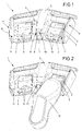
- 1 denotes a total of a foot switch having two actuators 2 in the form of buttons or switches.
- the actuators 2 are movably mounted about a pivot axis 3 and operable with the foot when the foot switch 1 rests on a substrate such as the floor of an operating room o.
- the actuators 2 are each surrounded by blocking elements 4, which are formed by a housing 5 of the foot holder 1.
- the blocking elements 4 are designed as two raised, lateral ribs 6 and as a central separating web 7, wherein the separating web 7 by an attachment 8 has an additionally increased height.
- detection areas 9 of proximity sensors 10 and 11 are provided.
- Each two 10 are arranged in the essay 8 as well in each case a proximity sensor 11 in a rib 6, wherein the proximity sensors are each configured as a light barrier and are arranged in pairs in the manner of a light barrier transmitted light variant.
- the proximity sensors 10 and 11 radiate through the respective detection area 9 and thus ensure, via the respective actuating member 2, the approach corridor above the respective actuating member 2.
- the proximity sensors 10 in the attachment 8 in each case radiate through the detection region 9 of a complete approach corridor, that is over the entire width of an actuator 2, up to a reflector arranged opposite in a rib 6, which is in this Case would be marked with 11.
- the reflector 11 in this embodiment reflects the light to the proximity sensor 10.
- the proximity sensor 10 in this embodiment thus comprises both light-emitting and light-receiving elements, so that a simplified cable management is possible, which leads into the attachment 8 of the divider 7 and there two proximity sensors 10.
- the proximity sensors 10 and 11 are arranged in the housing 5 of the foot switch 1. Deviating from this, differently configured proximity sensors can also be used or the proximity sensors can be arranged elsewhere.
- a proximity sensor can be realized, for example in the form of a capacitive sensor, so that when approaching a foot to the actuator 2, this proximity sensor is activated.
- Fig. 2 shows the footswitch 1 of Fig. 1 , wherein a shoe 12 is located in the detection area 9 of the right-hand actuator 2, even before the shoe 12 touches the actuator 2.
- a provided in the footswitch 1 or the footswitch 1 associated electronic circuit is operatively connected to the proximity sensors 10 and 11 of this right actuator 2 and activates a signal generator when the proximity sensor 10 and 11 detects the presence of the shoe 12.
- the subsequently generated signal differs from a signal which is emitted when the shoe 12 comes into the detection area 9 of the left actuator 2, so that the user receives an indication of which function by the respective signaling before actuation of the respective actuator 2 a connected to the footswitch 1 device he will soon trigger.
Landscapes
- Engineering & Computer Science (AREA)
- General Engineering & Computer Science (AREA)
- Theoretical Computer Science (AREA)
- Human Computer Interaction (AREA)
- Physics & Mathematics (AREA)
- General Physics & Mathematics (AREA)
- Push-Button Switches (AREA)
- Switches Operated By Changes In Physical Conditions (AREA)
Applications Claiming Priority (2)
| Application Number | Priority Date | Filing Date | Title |
|---|---|---|---|
| DE202010015472 | 2010-11-17 | ||
| DE202011000441U DE202011000441U1 (de) | 2010-11-17 | 2011-02-25 | Fußschalter mit Fußerkennung |
Publications (2)
| Publication Number | Publication Date |
|---|---|
| EP2456072A2 true EP2456072A2 (fr) | 2012-05-23 |
| EP2456072A3 EP2456072A3 (fr) | 2012-12-12 |
Family
ID=43993278
Family Applications (1)
| Application Number | Title | Priority Date | Filing Date |
|---|---|---|---|
| EP11188366A Withdrawn EP2456072A3 (fr) | 2010-11-17 | 2011-11-09 | Interrupteur à commande au pied doté d'une détection de pied |
Country Status (2)
| Country | Link |
|---|---|
| EP (1) | EP2456072A3 (fr) |
| DE (1) | DE202011000441U1 (fr) |
Families Citing this family (2)
| Publication number | Priority date | Publication date | Assignee | Title |
|---|---|---|---|---|
| DE102011082607B4 (de) * | 2011-09-13 | 2017-08-03 | Siemens Healthcare Gmbh | Aufnahmevorrichtung für ein kabellos betreibbares elektronisches Gerät, insbesondere einen Flachdetektor eines Röntgengerätes, und mobiles Röntgengerät |
| DE102018106737A1 (de) * | 2018-03-21 | 2019-09-26 | Olympus Winter & Ibe Gmbh | Elektrochirurgiesystem |
Family Cites Families (3)
| Publication number | Priority date | Publication date | Assignee | Title |
|---|---|---|---|---|
| US5422521A (en) * | 1993-11-18 | 1995-06-06 | Liebel-Flarsheim Co. | Foot operated control system for a multi-function device |
| DE102005043047B4 (de) * | 2005-09-09 | 2009-02-12 | Siemens Ag | Gerät mit Bedienschalter |
| DE202008013551U1 (de) * | 2008-10-15 | 2009-01-22 | steute Schaltgeräte GmbH & Co. KG | Multifunktions-Fußschalter |
-
2011
- 2011-02-25 DE DE202011000441U patent/DE202011000441U1/de not_active Expired - Lifetime
- 2011-11-09 EP EP11188366A patent/EP2456072A3/fr not_active Withdrawn
Non-Patent Citations (1)
| Title |
|---|
| None |
Also Published As
| Publication number | Publication date |
|---|---|
| DE202011000441U1 (de) | 2011-05-12 |
| EP2456072A3 (fr) | 2012-12-12 |
Similar Documents
| Publication | Publication Date | Title |
|---|---|---|
| EP1419432B1 (fr) | Dispositif pour la commande d'un appareil medical, notamment d'une table d'operation mobile | |
| DE60217917T2 (de) | Fuss-steuerung mit verriegelungsschaltung | |
| DE102014014498B4 (de) | Mit einem Touchscreen ausgestattetes Gerät sowie Verfahren zur Steuerung eines derartigen Geräts | |
| EP1930923B1 (fr) | Dispositif de commutation pour appareils médicaux ou chirurgicaux | |
| EP2455959A1 (fr) | Dispositif de commutation pour un appareil médical et procédé de fonctionnement du dispositif de commutation | |
| WO2016041683A1 (fr) | Dispositif d'affichage et de commande, notamment pour un véhicule à moteur, élément de commande et véhicule à moteur | |
| EP3643240A1 (fr) | Appareil d'imagerie médicale et procédé de fonctionnement d'un appareil d'imagerie médicale | |
| DE102012205549A1 (de) | Berührungslose Steuerung einer Schutzvorrichtung von motorgetriebenen Vorrichtungen in einem medizintechnischen Gerät | |
| WO2018114432A1 (fr) | Dispositif de commande commandable sans contact pour un véhicule à moteur ainsi que véhicule à moteur et procédé de fonctionnement du dispositif de commande | |
| WO2021028535A1 (fr) | Interface pour un dispositif médical avec un capteur d'actionnement adaptatif | |
| DE202008013551U1 (de) | Multifunktions-Fußschalter | |
| EP1090602A1 (fr) | Dispositif dentaire | |
| WO2021048833A1 (fr) | Télécommande pour commander un dispositif électronique | |
| EP2456072A2 (fr) | Interrupteur à commande au pied doté d'une détection de pied | |
| DE102013104429A1 (de) | Vorrichtungen zum Steuern einer medizinischen Vorrichtung mittels Gesten und Verfahren | |
| DE102005028215A1 (de) | Vorrichtung für die medizinische Versorgung | |
| DE102012213426A1 (de) | Medizinisches Gerät, gekennzeichnet durch Gestensteuerung | |
| WO2020233750A1 (fr) | Dispositif d'utilisation pour une table et table équipée de celui-ci | |
| WO2014111270A1 (fr) | Appareil de chirurgie ophtalmologique | |
| EP3880056B1 (fr) | Procédé et appareil pour exécuter différentes fonctions associées à des appareils chirurgicaux | |
| DE102015204767A1 (de) | Bedienung eines Medizingerätes | |
| DE102015005398A1 (de) | Bedienterminal | |
| WO2007134738A1 (fr) | Dispositif servant à influencer les fonctions d'un appareil par les mouvements du pied | |
| WO2003044287A2 (fr) | Dispositif pour l'actionnement manuel sans contact d'un appareil electrique | |
| WO2020053724A1 (fr) | Positionnement de caméras |
Legal Events
| Date | Code | Title | Description |
|---|---|---|---|
| PUAI | Public reference made under article 153(3) epc to a published international application that has entered the european phase |
Free format text: ORIGINAL CODE: 0009012 |
|
| AK | Designated contracting states |
Kind code of ref document: A2 Designated state(s): AL AT BE BG CH CY CZ DE DK EE ES FI FR GB GR HR HU IE IS IT LI LT LU LV MC MK MT NL NO PL PT RO RS SE SI SK SM TR |
|
| AX | Request for extension of the european patent |
Extension state: BA ME |
|
| PUAL | Search report despatched |
Free format text: ORIGINAL CODE: 0009013 |
|
| AK | Designated contracting states |
Kind code of ref document: A3 Designated state(s): AL AT BE BG CH CY CZ DE DK EE ES FI FR GB GR HR HU IE IS IT LI LT LU LV MC MK MT NL NO PL PT RO RS SE SI SK SM TR |
|
| AX | Request for extension of the european patent |
Extension state: BA ME |
|
| RIC1 | Information provided on ipc code assigned before grant |
Ipc: H01H 3/14 20060101ALI20121105BHEP Ipc: H03K 17/945 20060101AFI20121105BHEP |
|
| STAA | Information on the status of an ep patent application or granted ep patent |
Free format text: STATUS: THE APPLICATION IS DEEMED TO BE WITHDRAWN |
|
| 18D | Application deemed to be withdrawn |
Effective date: 20130613 |