EP2456357B1 - Appareil et procédé permettant d'influencer et/ou de détecter des particules magnétiques - Google Patents
Appareil et procédé permettant d'influencer et/ou de détecter des particules magnétiques Download PDFInfo
- Publication number
- EP2456357B1 EP2456357B1 EP10740364.4A EP10740364A EP2456357B1 EP 2456357 B1 EP2456357 B1 EP 2456357B1 EP 10740364 A EP10740364 A EP 10740364A EP 2456357 B1 EP2456357 B1 EP 2456357B1
- Authority
- EP
- European Patent Office
- Prior art keywords
- field
- detection signals
- magnetic
- voids
- aerosol
- Prior art date
- Legal status (The legal status is an assumption and is not a legal conclusion. Google has not performed a legal analysis and makes no representation as to the accuracy of the status listed.)
- Not-in-force
Links
- 239000006249 magnetic particle Substances 0.000 title claims description 54
- 238000000034 method Methods 0.000 title claims description 23
- 238000001514 detection method Methods 0.000 claims description 69
- 230000005291 magnetic effect Effects 0.000 claims description 51
- 239000000443 aerosol Substances 0.000 claims description 35
- 230000005415 magnetization Effects 0.000 claims description 26
- 239000011800 void material Substances 0.000 claims description 25
- 238000012545 processing Methods 0.000 claims description 14
- 238000004590 computer program Methods 0.000 claims description 10
- 230000008859 change Effects 0.000 claims description 9
- 230000001419 dependent effect Effects 0.000 claims description 7
- 239000000696 magnetic material Substances 0.000 claims description 4
- 210000004072 lung Anatomy 0.000 description 23
- 239000002245 particle Substances 0.000 description 20
- 230000036962 time dependent Effects 0.000 description 13
- 238000003384 imaging method Methods 0.000 description 11
- 238000009792 diffusion process Methods 0.000 description 10
- 210000003456 pulmonary alveoli Anatomy 0.000 description 9
- 239000002122 magnetic nanoparticle Substances 0.000 description 7
- 238000002595 magnetic resonance imaging Methods 0.000 description 6
- 206010014561 Emphysema Diseases 0.000 description 5
- 230000007274 generation of a signal involved in cell-cell signaling Effects 0.000 description 5
- 230000002123 temporal effect Effects 0.000 description 5
- 238000009826 distribution Methods 0.000 description 4
- 230000006870 function Effects 0.000 description 4
- 239000010410 layer Substances 0.000 description 4
- 230000003068 static effect Effects 0.000 description 4
- 208000006545 Chronic Obstructive Pulmonary Disease Diseases 0.000 description 3
- 230000009471 action Effects 0.000 description 3
- 230000008901 benefit Effects 0.000 description 3
- 230000007547 defect Effects 0.000 description 3
- 230000002950 deficient Effects 0.000 description 3
- 230000007246 mechanism Effects 0.000 description 3
- 230000008569 process Effects 0.000 description 3
- 239000007921 spray Substances 0.000 description 3
- 210000004712 air sac Anatomy 0.000 description 2
- 208000006673 asthma Diseases 0.000 description 2
- 238000002591 computed tomography Methods 0.000 description 2
- 238000010586 diagram Methods 0.000 description 2
- 230000000694 effects Effects 0.000 description 2
- 238000005516 engineering process Methods 0.000 description 2
- 238000001914 filtration Methods 0.000 description 2
- 239000006260 foam Substances 0.000 description 2
- 238000004519 manufacturing process Methods 0.000 description 2
- 238000005259 measurement Methods 0.000 description 2
- 239000000203 mixture Substances 0.000 description 2
- 238000012856 packing Methods 0.000 description 2
- 230000002829 reductive effect Effects 0.000 description 2
- 229920006395 saturated elastomer Polymers 0.000 description 2
- 238000001228 spectrum Methods 0.000 description 2
- XLYOFNOQVPJJNP-UHFFFAOYSA-N water Substances O XLYOFNOQVPJJNP-UHFFFAOYSA-N 0.000 description 2
- 229910001030 Iron–nickel alloy Inorganic materials 0.000 description 1
- 206010028980 Neoplasm Diseases 0.000 description 1
- 239000002253 acid Substances 0.000 description 1
- 150000007513 acids Chemical class 0.000 description 1
- 230000009286 beneficial effect Effects 0.000 description 1
- 230000015572 biosynthetic process Effects 0.000 description 1
- 230000036760 body temperature Effects 0.000 description 1
- 239000011248 coating agent Substances 0.000 description 1
- 239000011247 coating layer Substances 0.000 description 1
- 238000000576 coating method Methods 0.000 description 1
- 230000001427 coherent effect Effects 0.000 description 1
- 238000010276 construction Methods 0.000 description 1
- 239000002872 contrast media Substances 0.000 description 1
- 230000003111 delayed effect Effects 0.000 description 1
- 230000001066 destructive effect Effects 0.000 description 1
- 238000003745 diagnosis Methods 0.000 description 1
- 238000002059 diagnostic imaging Methods 0.000 description 1
- 201000010099 disease Diseases 0.000 description 1
- 208000037265 diseases, disorders, signs and symptoms Diseases 0.000 description 1
- 238000011156 evaluation Methods 0.000 description 1
- 238000001704 evaporation Methods 0.000 description 1
- 230000008020 evaporation Effects 0.000 description 1
- 239000003302 ferromagnetic material Substances 0.000 description 1
- 239000010419 fine particle Substances 0.000 description 1
- 230000004907 flux Effects 0.000 description 1
- 239000011521 glass Substances 0.000 description 1
- 231100001261 hazardous Toxicity 0.000 description 1
- 238000010438 heat treatment Methods 0.000 description 1
- 230000006872 improvement Effects 0.000 description 1
- 230000002452 interceptive effect Effects 0.000 description 1
- 230000000670 limiting effect Effects 0.000 description 1
- 239000007788 liquid Substances 0.000 description 1
- 239000006194 liquid suspension Substances 0.000 description 1
- 239000000463 material Substances 0.000 description 1
- 238000013178 mathematical model Methods 0.000 description 1
- 238000002156 mixing Methods 0.000 description 1
- 210000003097 mucus Anatomy 0.000 description 1
- 239000002105 nanoparticle Substances 0.000 description 1
- 229940031182 nanoparticles iron oxide Drugs 0.000 description 1
- 229910000889 permalloy Inorganic materials 0.000 description 1
- 230000035699 permeability Effects 0.000 description 1
- 230000002685 pulmonary effect Effects 0.000 description 1
- 230000004044 response Effects 0.000 description 1
- 238000001179 sorption measurement Methods 0.000 description 1
- 238000009987 spinning Methods 0.000 description 1
- 238000005507 spraying Methods 0.000 description 1
- 239000000758 substrate Substances 0.000 description 1
- 239000000725 suspension Substances 0.000 description 1
- 230000001225 therapeutic effect Effects 0.000 description 1
- 238000002560 therapeutic procedure Methods 0.000 description 1
- 238000012546 transfer Methods 0.000 description 1
- 238000009423 ventilation Methods 0.000 description 1
Images




Classifications
-
- A—HUMAN NECESSITIES
- A61—MEDICAL OR VETERINARY SCIENCE; HYGIENE
- A61B—DIAGNOSIS; SURGERY; IDENTIFICATION
- A61B5/00—Measuring for diagnostic purposes; Identification of persons
- A61B5/05—Detecting, measuring or recording for diagnosis by means of electric currents or magnetic fields; Measuring using microwaves or radio waves
-
- A—HUMAN NECESSITIES
- A61—MEDICAL OR VETERINARY SCIENCE; HYGIENE
- A61B—DIAGNOSIS; SURGERY; IDENTIFICATION
- A61B5/00—Measuring for diagnostic purposes; Identification of persons
- A61B5/05—Detecting, measuring or recording for diagnosis by means of electric currents or magnetic fields; Measuring using microwaves or radio waves
- A61B5/0515—Magnetic particle imaging
Definitions
- the present invention relates to an apparatus and a method for void size determination of voids within an object into which an aerosol containing magnetic particles has been introduced.
- the present invention particularly relates to an apparatus and a method for determining the size of a patient's pulmonary alveoli, said patient having inhaled an aerosol containing magnetic particles.
- the present invention relates to a computer program for implementing said method on a computer and for controlling such an apparatus.
- Magnetic Particle Imaging is an emerging medical imaging modality.
- the first versions of MPI were two-dimensional in that they produced two-dimensional images. Future versions will be three-dimensional (3D).
- a time-dependent, or 4D, image of a non-static object can be created by combining a temporal sequence of 3D images to a movie, provided the object does not significantly change during the data acquisition for a single 3D image.
- MPI is a reconstructive imaging method, like Computed Tomography (CT) or Magnetic Resonance Imaging (MRI). Accordingly, an MP image of an object's volume of interest is generated in two steps.
- the first step referred to as data acquisition, is performed using an MPI scanner.
- the MPI scanner has means to generate a static magnetic gradient field, called “selection field”, which has a single field free point (FFP) at the isocenter of the scanner.
- selection field which has a single field free point (FFP) at the isocenter of the scanner.
- FFP single field free point
- the scanner has means to generate a time-dependent, spatially nearly homogeneous magnetic field. Actually, this field is obtained by superposing a rapidly changing field with a small amplitude, called “drive field”, and a slowly varying field with a large amplitude, called "focus field”.
- the FFP may be moved along a predetermined FFP trajectory throughout a volume of scanning surrounding the isocenter.
- the scanner also has an arrangement of one or more, e.g. three, receive coils and can record any voltages induced in these coils.
- the object to be imaged is placed in the scanner such that the object's volume of interest is enclosed by the scanner's field of view, which is a subset of the volume of scanning.
- the object must contain magnetic nanoparticles; if the object is an animal or a patient, a contrast agent containing such particles is administered to the animal or patient prior to the scan.
- the MPI scanner steers the FFP along a deliberately chosen trajectory that traces out the volume of scanning, or at least the field of view.
- the magnetic nanoparticles within the object experience a changing magnetic field and respond by changing their magnetization.
- the changing magnetization of the nanoparticles induces a time dependent voltage in each of the receive coils. This voltage is sampled in a receiver associated with the receive coil.
- the samples output by the receivers are recorded and constitute the acquired data.
- the parameters that control the details of the data acquisition make up the scan protocol.
- the image is computed, or reconstructed, from the data acquired in the first step.
- the image is a discrete 3D array of data that represents a sampled approximation to the position-dependent concentration of the magnetic nanoparticles in the field of view.
- the reconstruction is generally performed by a computer, which executes a suitable computer program. Computer and computer program realize a reconstruction algorithm.
- the reconstruction algorithm is based on a mathematical model of the data acquisition. As with all reconstructive imaging methods, this model is an integral operator that acts on the acquired data; the reconstruction algorithm tries to undo, to the extent possible, the action of the model.
- Such an MPI apparatus and method have the advantage that they can be used to examine arbitrary examination objects - e. g. human bodies - in a non-destructive manner and without causing any damage and with a high spatial resolution, both close to the surface and remote from the surface of the examination object.
- Such an arrangement and method are generally known and are first described in DE 101 51 778 A1 and in Gleich, B. and Weizenecker, J. (2005), "Tomographic imaging using the nonlinear response of magnetic particles" in nature, vol. 435, pp. 1214-1217 .
- the arrangement and method for magnetic particle imaging (MPI) described in that publication take advantage of the non-linear magnetization curve of small magnetic particles.
- MRI Magnetic Resonance Imaging
- the diffusion parameters of gasses may reveal deeper insight into the structure of the lung revealing potentially important information for asthma, emphysema and chronic obstructive pulmonary disease.
- the apparent diffusion coefficient is linked to the average distance to the lung surface, thus a large diffusion indicates e.g. enlarged alveoli.
- an apparatus comprising:
- a computer program comprising program code means for causing a computer to control the apparatus according to the present invention to carry out the steps of the method according to the present invention when said computer program is carried out on the computer.
- the present invention is based on the idea to that MPI offers a possibility to reveal information concerning the lung structure or, more generally, about the size of voids existing within an object. Such a contrast can be based on the signal generation in the air space due to fast Brownian rotation mechanisms.
- MPI usually the Brownian rotation is excluded as an effective mechanism for signal generation in a liquid suspension.
- the viscosity of air is only 18 ⁇ Pas leading to a more than 50 times the magnetization speed in water. Therefore, it is possible to efficiently detect magnetic particles in the air space, even if the anisotropy is so high that the Neel process is blocked.
- the Brownian rotation is blocked and the MPI signal ("detection signal") vanishes.
- the magnetic particles will reach the lung surface (void's wall) by diffusion.
- the air space is enlarged, which is detectable using MPI.
- the signal decay time of the detection signals is exploited to get information about the size of the alveoli, which then allows determining whether or not there are any defects.
- the size of the voids can be determined in an embodiment by exploiting the the signal decay time of the detection signals.
- the magnetic particles are preferably sprayed to a fine aerosol and inhaled by the patient (or, generally, introduced into the object) prior to the application of the method according to the present invention, i.e. prior to application of the magnetic fields for acquiring detection signals.
- an embodiment of the apparatus according to the present invention comprises an aerosol generator, in particular generating an aerosol with singularized magnetic particles.
- first detection signals are acquired directly after inhalation/introduction of the aerosol and second detection signals are acquired after a time duration after inhalation/introduction of the aerosol, i.e. after the inhaled magnetic particles contained in the aerosol had some time to travel (i.e. diffuse) in the alveoli/voids.
- the magnetic particles have not yet reached the lung surface/void's wall (.i.e. the surface of the alveolus/void in which they are travelling)
- their viscosity is comparably low so that a comparably high detection signal is acquired from those magnetic particles.
- the magnetic particles have reached the lung surface /void's wall, their viscosity is comparably high so that a comparably low detection signal is acquired from those magnetic particles.
- differences of the detection signals can be determined, provided the time gap between the acquisition of the first and second detection signals is long enough to allow the magnetic particles to travel a certain distance.
- the invention can be applied for determining the size of voids of different sizes, including sizes below the resolution of the detection signals. If applied for determining the size of alveoli, the resolution of the detection signals is generally larger than the size of single alveoli. In such cases, a single voxel of an image reconstructed from the detection signals covers a group of alveoli.
- Areas of application are, besides medical applications for determining the size of a patient's alveoli, production technologies, e.g. for determining the size of voids in a workpiece (e.g. a foam) to confirm that the mean size of voids is below a predetermined threshold or that a maximum size is not exceeded.
- Another application is to determine how compact a bulk good is packed, e.g. to find out if there are large unused areas in the packing.
- the delay time between the acquisition of the first and second detection signals depends on the viscosity of the medium within the voids and the void size. For size measurements of alveoli, a typical delay time will be between 1 and 5 seconds. However, it is preferred to acquire more than two sets of detection signals at subsequent time intervals.
- the mean size of alveoli is determined.
- a respective threshold value for the alveolus size is used to differentiate between healthy (small) and unhealthy (large) alveoli. This is required since the size and occurrence of alveoli varies within the lung.
- Such thresholds are generally obtained in advance, preferably for various diseases of the lung. The same holds generally for non-medical applications, where information about typical and non-typical void sizes is obtained for use in determining a typical threshold.
- the invention can be applied for determining the size of voids of different sizes, including sizes below the resolution of the detection signals. If applied for determining the size of alveoli, the resolution of the detection signals is generally larger than the size of single alveoli. In such cases, a single voxel of an image reconstructed from the detection signals covers a group of alveoli. In an embodiment it is also possible to determine means values for the sizes over groups of alveoli. Preferably, the size determination is done for the complete lung, but also a restriction to certain areas is possible, e.g. if there areas are under suspect for comprising defective alveoli.
- Areas of application are, besides medical applications for determining the size of a patient's alveoli, production technologies, e.g. for determining the size of voids in a workpiece (e.g. a foam) to confirm that the mean size of voids is below a predetermined threshold or that a maximum size is not exceeded.
- Another application is to determine how compact a bulk good is packed, e.g. to find out if there are large unused areas in the packing.
- the void size of voids within the object is determined by comparing the first and second detection signals, in particular for predetermined areas in the field of view. From the determined difference, e.g.
- information can be gained about the travelling time of the magnetic particles and/or an estimate of the percentage of magnetic particles that have attached to the lung (or object) surface after a certain period of time can be made, allowing to retrieve information about the size of the alveoli (or voids) and, thus, about possible defects of the lung.
- the processing means is adapted for generating an intensity decay image and/or a decay time image from the determined intensity of the signal decay or the determined signal decay time, respectively.
- an image provides and visually displays the additional information in which areas of the lung (or object) possible defects, e.g. enlarged alveoli, are present or in which areas the voids are larger (or smaller) as desired.
- the void size of voids within the object is determined by generating a first image and a second image from the first and second detection signals, in particular for the predetermined areas in the field of view, and for comparing said first and second images.
- the acquired detection signals are not compared directly, but images are first generated therefrom, which are then compared.
- the images generated from the first and second detection signals and/or a difference image therefrom are displayed. It is also possible to use image (or pattern) recognition tools to automatically find unusual areas in the images, in particular in the difference image.
- both alternative embodiments are equally valuable and mathematically equivalent. It might be more illustrative for the user to first generate images and then determine a significant parameter, e.g. a signal decay time, therefrom. If signal can also be obtained from adsorbed particles, then the use of the detection signals might be better. Since in the second (and further) signal acquisitions it is already known, how many particles are adsorbed, the detection signal can be better fitted (using two system functions, one for particles in the aerosol and one for adsorbed particles).
- the first embodiment 10 of an MPI scanner shown in Fig. 1 has three prominent pairs 12, 14, 16 of coaxial parallel circular coils, each pair being arranged as illustrated in Fig. 1 .
- These coil pairs 12, 14, 16 serve to generate the selection field as well as the drive and focus fields.
- the axes 18, 20, 22 of the three coil pairs 12, 14, 16 are mutually orthogonal and meet in a single point, designated the isocenter 24 of the MPI scanner 10.
- these axes 18, 20, 22 serve as the axes of a 3D Cartesian x-y-z coordinate system attached to the isocenter 24.
- the vertical axis 20 is nominated the y-axis, so that the x and z-axes are horizontal.
- the coil pairs 12, 14, 16 are also named after their axes.
- the y-coil pair 14 is formed by the coils at the top and the bottom of the scanner. Moreover, the coil with the positive (negative) y-coordinate is called the y + -coil (y - -coil), and similarly for the remaining coils.
- the scanner 10 can be set to direct a predetermined, time dependent electric current through each of these coils 12, 14, 16, and in either direction. If the current flows clockwise around a coil when seen along this coil's axis, it will be taken as positive, otherwise as negative. To generate the static selection field, a constant positive current I s is made to flow through the z + -coil, and the current - I S is made to flow through the z - -coil. The z-coil pair 16 then acts as an anti-parallel circular coil pair.
- the magnetic selection field which is generally a gradient magnetic field is represented in Fig. 2 by the field lines 50. It has a substantially constant gradient in the direction of the (e.g. horizontal) z-axis 22 of the z-coil pair 16 generating the selection field and reaches the value zero in the isocenter 24 on this axis 22. Starting from this field-free point (not individually shown in Fig. 2 ), the field strength of the magnetic selection field 50 increases in all three spatial directions as the distance increases from the field-free point.
- first sub-zone or region 52 which is denoted by a dashed line around the isocenter 24 the field strength is so small that the magnetization of particles present in that first sub-zone 52 is not saturated, whereas the magnetization of particles present in a second sub-zone 54 (outside the region 52) is in a state of saturation.
- the field-free point or first sub-zone 52 of the scanner's field of view 28 is preferably a spatially coherent area; it may also be a punctiform area, a line or a flat area.
- the magnetic field strength of the selection field is sufficiently strong to keep the magnetic particles in a state of saturation.
- the (overall) magnetization in the field of view 28 changes.
- information about the spatial distribution of the magnetic particles in the field of view 28 can be obtained.
- further magnetic fields i.e. the magnetic drive field, and, if applicable, the magnetic focus field, are superposed to the selection field 50 in the field of view 28 or at least in a part of the field of view 28.
- a time dependent current I D 1 is made to flow through both x-coils 12, a time dependent current I D 2 through both y-coils 14, and a time dependent current I D 3 through both z-coils 16.
- each of the three coil pairs acts as a parallel circular coil pair.
- a time dependent current I F 1 is made to flow through both x-coils 12, a current I F 2 through both y-coils 14, and a current I F 3 through both z-coils 16.
- the z-coil pair 16 is special: It generates not only its share of the drive and focus fields, but also the selection field.
- the current flowing through the z ⁇ -coil is I D 3 + I F 3 + I S .
- the selection field Being generated by an anti-parallel circular coil pair, the selection field is rotationally symmetric about the z-axis, and its z-component is nearly linear in z and independent of x and y in a sizeable volume around the isocenter 24.
- the selection field has a single field free point (FFP) at the isocenter.
- FFP field free point
- the contributions to the drive and focus fields, which are generated by parallel circular coil pairs are spatially nearly homogeneous in a sizeable volume around the isocenter 24 and parallel to the axis of the respective coil pair.
- the drive and focus fields jointly generated by all three parallel circular coil pairs are spatially nearly homogeneous and can be given any direction and strength, up to some maximum strength.
- the drive and focus fields are also time dependent.
- the difference between the focus field and the drive field is that the focus field varies slowly in time and has a large amplitude while the drive field varies rapidly and has a small amplitude. There are physical and biomedical reasons to treat these fields differently. A rapidly varying field with a large amplitude would be difficult to generate and hazardous to the patient.
- the embodiment 10 of the MPI scanner has at least one further pair, preferably three further pairs, of parallel circular coils, again oriented along the x-, y-, and z-axes.
- These coil pairs which are not shown in Fig. 1 , serve as receive coils.
- the magnetic field generated by a constant current flowing through one of these receive coil pairs is spatially nearly homogeneous within the field of view and parallel to the axis of the respective coil pair.
- the receive coils are supposed to be well decoupled.
- the time dependent voltage induced in a receive coil is amplified and sampled by a receiver attached to this coil. More precisely, to cope with the enormous dynamic range of this signal, the receiver samples the difference between the received signal and a reference signal.
- the transfer function of the receiver is non-zero from DC up to the point where the expected signal level drops below the noise level.
- the embodiment 10 of the MPI scanner shown in Fig. 1 has a cylindrical bore 26 along the z-axis 22, i.e. along the axis of the selection field. All coils are placed outside this bore 26.
- the patient (or object) to be imaged (or treated) is placed in the bore 26 such that the patient's volume of interest - that volume of the patient (or object) that shall be imaged (or treated) - is enclosed by the scanner's field of view 28 - that volume of the scanner whose contents the scanner can image.
- the patient (or object) is, for instance, placed on a patient table.
- the field of view 28 is a geometrically simple, isocentric volume in the interior of the bore 26, such as a cube, a ball, or a cylinder.
- a cubical field of view 28 is illustrated in Fig. 1 .
- the size of the first sub-zone 52 is dependent on the one hand on the strength of the gradient of the magnetic selection field and on the other hand on the field strength of the magnetic field required for saturation.
- the first sub-zone 52 in which the magnetization of the particles is not saturated has dimensions of about 1 mm (in the given space direction).
- the patient's volume of interest is supposed to contain magnetic nanoparticles.
- the magnetic particles are positioned in the volume of interest, e.g. by means of a liquid comprising the magnetic particles which is injected into the body of the patient (object) or otherwise administered, e.g. orally, to the patient.
- An embodiment of magnetic particles comprises, for example, a spherical substrate, for example, of glass which is provided with a soft-magnetic layer which has a thickness of, for example, 5 nm and consists, for example, of an iron-nickel alloy (for example, Permalloy).
- This layer may be covered, for example, by means of a coating layer which protects the particle against chemically and/or physically aggressive environments, e.g. acids.
- the magnetic field strength of the magnetic selection field 50 required for the saturation of the magnetization of such particles is dependent on various parameters, e.g. the diameter of the particles, the used magnetic material for the magnetic layer and other parameters. In the case of e.g.
- a magnetic field of approximately 800 A/m (corresponding approximately to a flux density of 1 mT) is then required, whereas in the case of a diameter of 100 ⁇ m a magnetic field of 80 A/m suffices.
- Magnetic particles that can generally be used are available on the market under the trade name Resovist.
- the data acquisition starts at time t s and ends at time t e .
- the x-, y-, and z-coil pairs 12, 14, 16 generate a position- and time dependent magnetic field, the applied field. This is achieved by directing suitable currents through the coils.
- the drive and focus fields push the selection field around such that the FFP moves along a preselected FFP trajectory that traces out the volume of scanning - a superset of the field of view.
- the applied field orientates the magnetic nanoparticles in the patient. As the applied field changes, the resulting magnetization changes too, though it responds nonlinearly to the applied field.
- the sum of the changing applied field and the changing magnetization induces a time dependent voltage V k across the terminals of receive coil pair along the x k -axis.
- the associated receiver converts this voltage to a signal S k (t), which it samples and outputs.
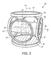
- the second embodiment 30 of the MPI scanner shown in Fig. 3 has three circular and mutually orthogonal coil pairs 32, 34, 36, but these coil pairs 32, 34, 36 generate the selection field and the focus field only.
- the z-coils 36 which again generate the selection field, are filled with ferromagnetic material 37.
- the z-axis 42 of this embodiment 30 is oriented vertically, while the x- and y-axes 38, 40 are oriented horizontally.
- the bore 46 of the scanner is parallel to the x-axis 38 and, thus, perpendicular to the axis 42 of the selection field.
- the drive field is generated by a solenoid (not shown) along the x-axis 38 and by pairs of saddle coils (not shown) along the two remaining axes 40, 42. These coils are wound around a tube which forms the bore.
- the drive field coils also serve as receive coils. The signals picked up by the receive coils are sent through a high-pass filter that suppresses the contribution caused by the applied field.
- the selection field generated does either not vary at all over the time or the variation is comparably slow, preferably between approximately 1 Hz and approximately 100 Hz.
- the temporal frequency spectrum of the drive field is concentrated in a narrow band around 25 kHz (up to approximately 100 kHz).
- the useful frequency spectrum of the received signals lies between 50 kHz and 1 MHz (eventually up to approximately 10 MHz).
- the bore has a diameter of 120 mm.
- the biggest cube 48 that fits into the bore 46 has an edge length of 120 mm / 2 ⁇ 84 mm .
- the various magnetic fields can be generated by coils of the same coils pairs and by providing these coils with appropriately generated currents.
- the temporally constant (or quasi constant) selection field and the temporally variable drive field and focus field are generated by separate coil pairs.
- coil pairs of the Helmholtz type can be used for these coils, which are generally known, e.g. from the field of magnetic resonance apparatus with open magnets (open MRI) in which a radio frequency (RF) coil pair is situated above and below the region of interest, said RF coil pair being capable of generating a temporally variable magnetic field. Therefore, the construction of such coils need not be further elaborated herein.
- the selection field can be generated by a mixture of at least one permanent magnet and at least one coil.
- Fig. 4 shows a general block diagram of an MPI apparatus 10 according to the present invention.
- the general principles of magnetic particle imaging and of magnetic resonance imaging explained above are valid and applicable to this embodiment as well, unless otherwise specified.
- the embodiment of the apparatus 100 shown in Fig. 4 comprises a set of various coils for generating the desired magnetic fields. First, the coils and their functions in a MPI mode shall be explained.
- selection means comprising a set of selection field (SF) coils 116, preferably comprising at least one pair of coil elements.
- the selection means further comprises a selection field signal generator unit 110.
- a separate generator subunit is provided for each coil element (or each pair of coil elements) of the set 116 of selection field coils.
- Said selection field signal generator unit 110 comprises a controllable selection field current source 112 (generally including an amplifier) and a filter unit 114 which provide the respective section field coil element with the selection field current to individually set the gradient strength of the selection field in the desired direction.
- a DC current is provided. If the selection field coil elements are arranged as opposed coils, e.g. on opposite sides of the field of view, the selection field currents of opposed coils are preferably oppositely oriented.
- the selection field signal generator unit 110 is controlled by a control unit 150, which preferably controls the selection field current generation 110 such that the sum of the field strength and the sum of the gradient strength of all spatial fractions of the selection field is maintained at a predefined level.
- the apparatus 100 further comprises focus means comprising a set of focus field (FF) coils, preferably comprising three pairs 126a, 126b, 126c of oppositely arranged focus field coil elements.
- Said magnetic focus field is generally used for changing the position in space of the region of action.
- the focus field coils are controlled by a focus field signal generator unit 120, preferably comprising a separate focus field signal generation subunit for each coil element (or at least each pair of coil elements) of said set of focus field coils.
- Said focus field signal generator unit 120 comprises a focus field current source 122 (preferably comprising a current amplifier) and a filter unit 124 for providing a focus field current to the respective coil of said subset of coils 126a, 126b, 126c which shall be used for generating the magnetic focus field.
- the focus field current unit 120 is also controlled by the control unit 150.
- the apparatus 100 further comprises drive means comprising a subset of drive field (DF) coils, preferably comprising three pairs 136a, 136b, 136c of oppositely arranged drive field coil elements.
- the drive field coils are controlled by a drive field signal generator unit 130, preferably comprising a separate drive field signal generation subunit for each coil element (or at least each pair of coil elements) of said set of drive field coils.
- Said drive field signal generator unit 130 comprises a drive field current source 41 (preferably including a current amplifier) and a filter unit 42 for providing a drive field current to the respective drive field coil.
- the drive field current source 41 is adapted for generating an AC current and is also controlled by the control unit 150.
- Said signal receiving unit 140 comprises a filter unit 142 for filtering the received detection signals.
- the aim of this filtering is to separate measured values, which are caused by the magnetization in the examination area which is influenced by the change in position of the two part-regions (52, 54), from other, interfering signals.
- the filter unit 142 may be designed for example such that signals which have temporal frequencies that are smaller than the temporal frequencies with which the receiving coil 148 is operated, or smaller than twice these temporal frequencies, do not pass the filter unit 142.
- the signals are then transmitted via an amplifier unit 144 to an analog/digital converter 146 (ADC).
- ADC analog/digital converter
- the digitalized signals produced by the analog/digital converter 146 are fed to an image processing unit (also called reconstruction means) 152, which reconstructs the spatial distribution of the magnetic particles from these signals and the respective position which the first part-region 52 of the first magnetic field in the examination area assumed during receipt of the respective signal and which the image processing unit 152 obtains from the control unit 150.
- the reconstructed spatial distribution of the magnetic particles is finally transmitted via the control means 150 to a computer 154, which displays it on a monitor 156.
- a computer 154 which displays it on a monitor 156.
- an image can be displayed showing the distribution of magnetic particles in the field of view of the examination area.
- an input unit 158 is provided, for example a keyboard.
- a user is therefore able to set the desired direction of the highest resolution and in turn receives the respective image of the region of action on the monitor 156. If the critical direction, in which the highest resolution is needed, deviates from the direction set first by the user, the user can still vary the direction manually in order to produce a further image with an improved imaging resolution.
- This resolution improvement process can also be operated automatically by the control unit 150 and the computer 154.
- the control unit 150 in this embodiment sets the gradient field in a first direction which is automatically estimated or set as start value by the user.
- the direction of the gradient field is then varied stepwise until the resolution of the thereby received images, which are compared by the computer 154, is maximal, respectively not improved anymore.
- the most critical direction can therefore be found respectively adapted automatically in order to receive the highest possible resolution.
- the computer (or, more generally, processing means) 154 is adapted for determining the size of alveoli from first detection signals acquired directly after inhalation of the aerosol and second detection signals acquired after a time duration after inhalation of the aerosol.
- the control unit 150 thus controls the various signal generation means 110, 120, 130 to generate and provide appropriate control currents to the respective coils 116, 126, 136 so that they generate magnetic fields by which the field free point (FFP) 52 (i.e. the first sub-region) is moved along a predetermined trajectory through a region of interest in the field of view 28.
- FFP field free point
- the detection signals are acquired which are thereafter processed and evaluated by the computer 154.
- This FFP movement is done at least twice, preferably along the same trajectory, and detection signals are acquired at least twice from the same region of interest (and, preferably, from the same locations within the region of interest).
- the first FFP movement and signal acquisition is done immediately or shortly (generally not more than 5 seconds) after the inhalation of the aerosol, and the second FFP movement and signal acquisition is done a short time (e.g. 1 to 5 seconds) after the first FFP movement and signal acquisition.
- the signal acquisition is already started during the inhalation, and the first data set (or image reconstructed therefrom) is used as first (reference) data set. For obtaining a full data set of detection signals of the lung, 0.5 to 1 second should be sufficient.
- the inhaled aerosol comprises very small magnetic nano-particles which are able to diffuse within the alveoli after inhalation. If they reach the surface of the alveoli, they remain attached to the surface and have a reduced viscosity compared to the previous state when they diffuse within the alveoli. This, however, means that from magnetic particles that are attached to the surface of the alveoli, a lower detection signal is emitted (and detected by the receiving coil 148) compared to magnetic particles that are freely diffusing within the alveoli from which a higher detection signal can be obtained.
- This knowledge is exploited according to the present invention by evaluating the at least two sets of detection signals acquired at different moments in time after inhalation of the magnetic particles. Since the second detection signals are required when at least part of the magnetic particles are already attached to the surface of the alveoli, lower signal intensities are expected.
- the amount of the drop in signal intensity and/or the signal decay time depends on the size of the alveoli. In particular, if the alveoli are enlarged, as is the case for emphysema, it takes a longer time until the magnetic particles diffuse up to the alveoli's surface, whereas this time is shorter for smaller (healthy) alveoli. In other words, if there is a large diffusion and a slow signal decay time, this is an indication for enlarged alveoli and, thus, for emphysema.
- the computer 154 is thus adapted for appropriately evaluating the acquired detection signals, for instance by comparing the detection signals, in particular the signal decay time and/or the signal intensities. It is also possible to determine images from both sets of detection signals separately and thereafter to generate a difference image which can give information about the areas with defective alveoli.
- the invention can be applied to determine whether or not there is emphysema. As shown in Fig. 5 , an emphysematic alveolus ( Fig. 5b ) is enlarged compared to a healthy alveolus ( Fig. 5a ).
- the invention can further be applied to determine whether or not the patient suffers from asthma, in which the airways of the lung are inflamed (swollen), or suffers from chronic obstructive pulmonary disease (COPD) in which the airways and air sacs loose their elastic quality, the walls between many of the air sacs are destroyed, the walls of the airways become thick and inflamed (swollen) and/or the airways make more mucus than usual, which tends to clog the airways.
- COPD chronic obstructive pulmonary disease
- the main essential effect of the present invention thus is to provide the ability to determine the (average) size of alveoli or, more generally, of voids in an object.
- the aerosol containing the (very) fine magnetic particles can be produced by a spraying process. Ideally, there are only individual particles. Therefore, high pressure devices or an electro-spray mechanism could be used. To assist the formation of fine particles it is beneficial, if a sufficient low initial particle concentration is used such that only one particle is in one droplet. Then, the water is evaporated using a mixing with dry air and heating to body temperature. To achieve a fine spray, the amount of air needed for the evaporation may result in a too low particle concentration. This problem can be solved by concentration the aerosol particles in spinning air vortexes by centrifugal forces.
- the apparent diffusion coefficient is preferably calculated using a computer program evaluating the acquired detection signals, e.g. the decay and change of the detection signals in air space.
- the time constant of the signal decay may be plotted directly.
- the present invention proposes to use for ventilation measurement.
- An aerosol of a magnetic nano-particle suspension in particular a nano-spray, has to be inhaled by the patient for assessing the diffusion in the lung.
- suitable magnetic particles a difference in the signature of the aerosol and adsorbed particles can be imaged.
- the apparent diffusion coefficient is calculated evaluating the detection signals acquired subsequently after inhalation of the aerosol. For instance, the time constant per particle adsorption in the lung tissue can be determined.
Landscapes
- Health & Medical Sciences (AREA)
- Life Sciences & Earth Sciences (AREA)
- Nuclear Medicine, Radiotherapy & Molecular Imaging (AREA)
- Biomedical Technology (AREA)
- Medical Informatics (AREA)
- Biophysics (AREA)
- Pathology (AREA)
- Engineering & Computer Science (AREA)
- Radiology & Medical Imaging (AREA)
- Heart & Thoracic Surgery (AREA)
- Physics & Mathematics (AREA)
- Molecular Biology (AREA)
- Surgery (AREA)
- Animal Behavior & Ethology (AREA)
- General Health & Medical Sciences (AREA)
- Public Health (AREA)
- Veterinary Medicine (AREA)
- Magnetic Resonance Imaging Apparatus (AREA)
- Investigating Or Analyzing Materials By The Use Of Magnetic Means (AREA)
Claims (12)
- Appareil (100) de détermination de la taille des vides au sein d'un objet, un aérosol contenant des particules magnétiques ayant été introduit dans les vides, l'appareil comprenant :- un moyen de sélection comprenant une unité de générateur de signal de champ de sélection (110) et des éléments de génération de champ de sélection (116) servant à générer un champ magnétique de sélection (50) présentant un profil dans l'espace de son intensité de champ magnétique tel qu'une première sous-zone (52) présentant une intensité de champ magnétique basse et une seconde sous-zone (54) présentant une intensité de champ magnétique plus élevée sont formées dans un champ de vue (28),- un moyen d'entraînement comprenant des unités de générateur de signal de champ d'entraînement (130) et des bobines de champ d'entraînement (136a, 136b, 136c) servant à changer la position dans l'espace des deux sous-zones (52, 54) dans le champ de vue (28) au moyen d'un champ magnétique d'entraînement de façon que l'aimantation de la matière magnétique change localement,- un moyen de réception comprenant au moins une unité de réception de signal (140) et au moins une bobine de réception (148) servant à acquérir des signaux de détection, les signaux de détection étant dépendants de l'aimantation dans le champ de vue (28), ladite aimantation étant influencée par le changement de position dans l'espace de la première et de la seconde sous-zone (52, 54), et- un moyen de traitement (154) conçu pour déterminer la taille desdites vides au sein de l'objet à partir de premiers signaux de détection acquis directement après l'introduction de l'aérosol et de seconds signaux de détection acquis après un certain temps après l'introduction de l'aérosol.
- Appareil (100) selon la revendication 1,
dans lequel ledit moyen de traitement (154) est conçu pour déterminer la taille des vides au sein de l'objet par la comparaison des premiers et des seconds signaux de détection, en particulier pour des zones prédéterminées dans le champ de vue (28). - Appareil (100) selon la revendication 2,
dans lequel ledit moyen de traitement (154) est conçu pour déterminer la taille des vides au sein de l'objet par la détermination de l'intensité de la décroissance du signal à partir de la comparaison des premiers et des seconds signaux de détection, en particulier pour les zones prédéterminées dans le champ de vue (28). - Appareil (100) selon la revendication 2,
dans lequel ledit moyen de traitement (154) est conçu pour déterminer la taille des vides au sein de l'objet par la détermination de la durée de décroissance du signal à partir de la comparaison des premiers et des seconds signaux de détection, en particulier pour les zones prédéterminées dans le champ de vue (28). - Appareil (100) selon la revendication 3 ou 4,
dans lequel ledit moyen de traitement (154) est conçu pour générer une image de décroissance d'intensité et/ou une image de temps de décroissance, respectivement à partir de l'intensité déterminée de la décroissance du signal ou du temps déterminé de décroissance du signal. - Appareil (100) selon la revendication 1,
dans lequel ledit moyen de traitement (154) est conçu pour déterminer la taille des vides au sein de l'objet par la génération d'une première image et d'une seconde image à partir des premiers et des seconds signaux de détection, en particulier pour les zones prédéterminées dans le champ de vue (28), et pour comparer ladite première image et ladite seconde image. - Appareil (100) selon la revendication 6,
dans lequel ledit moyen de traitement (154) est conçu pour générer une image de différence à partir d'une soustraction dépendant de la position entre la première image et la seconde image, en particulier pour les zones prédéterminées dans le champ de vue (28). - Appareil (100) selon l'une quelconque des revendications 2 à 7,
dans lequel lesdites zones prédéterminées sont un vide unique ou un groupe de vides. - Appareil (100) selon la revendication 1,
dans lequel ledit moyen de traitement (154) est conçu pour déterminer la taille des vides au sein de l'objet à partir d'une pluralité de signaux de détection acquis après l'introduction de l'aérosol à des moments ultérieurs dans le temps. - Appareil (100) selon la revendication 1,
comprenant en outre un générateur d'aérosol servant à générer un aérosol contenant des particules magnétiques, en particulier pour singulariser les particules magnétiques dans l'aérosol. - Procédé de détermination de la taille des vides au sein d'un objet, un aérosol contenant des particules magnétiques ayant été introduit dans les vides, le procédé comprenant les étapes suivantes :- la génération d'un champ magnétique de sélection (50) présentant un profil dans l'espace de son intensité de champ magnétique tel qu'une première sous-zone (52) présentant une intensité de champ magnétique basse et une seconde sous-zone (54) présentant une intensité de champ magnétique plus élevée sont formées dans un champ de vue (28) par un moyen de sélection comprenant une unité de générateur de signal de champ de sélection (110) et des éléments de génération de champ de sélection (116),- le changement de la position dans l'espace des deux sous-zones (52, 54) dans le champ de vue (28) au moyen d'un champ magnétique d'entraînement de façon que l'aimantation de la matière magnétique change localement, par un moyen d'entraînement comprenant des unités de générateur de signal de champ d'entraînement (130) et des bobines de champ d'entraînement (136a, 136b, 136c),- l'acquisition de signaux de détection, les signaux de détection étant dépendants de l'aimantation dans le champ de vue (28), ladite aimantation étant influencée par le changement de position dans l'espace de la première et de la seconde sous-zone (52, 54), par un moyen de réception comprenant au moins une unité de réception de signal (140) et au moins une bobine de réception (148), et- la détermination de la taille desdites vides au sein de l'objet à partir des premiers signaux de détection acquis directement après l'introduction de l'aérosol et de seconds signaux de détection acquis après un certain temps après l'introduction d'un aérosol.
- Programme informatique, comprenant un moyen de code de programme servant à amener un ordinateur à commander un appareil selon la revendication 1 pour mettre en oeuvre les étapes du procédé selon la revendication 11 quand ledit programme informatique est exécuté sur l'ordinateur.
Priority Applications (1)
| Application Number | Priority Date | Filing Date | Title |
|---|---|---|---|
| EP10740364.4A EP2456357B1 (fr) | 2009-07-20 | 2010-07-12 | Appareil et procédé permettant d'influencer et/ou de détecter des particules magnétiques |
Applications Claiming Priority (3)
| Application Number | Priority Date | Filing Date | Title |
|---|---|---|---|
| EP09165864 | 2009-07-20 | ||
| PCT/IB2010/053182 WO2011010243A1 (fr) | 2009-07-20 | 2010-07-12 | Appareil et procédé permettant d'influencer et/ou de détecter des particules magnétiques |
| EP10740364.4A EP2456357B1 (fr) | 2009-07-20 | 2010-07-12 | Appareil et procédé permettant d'influencer et/ou de détecter des particules magnétiques |
Publications (2)
| Publication Number | Publication Date |
|---|---|
| EP2456357A1 EP2456357A1 (fr) | 2012-05-30 |
| EP2456357B1 true EP2456357B1 (fr) | 2014-09-10 |
Family
ID=42939556
Family Applications (1)
| Application Number | Title | Priority Date | Filing Date |
|---|---|---|---|
| EP10740364.4A Not-in-force EP2456357B1 (fr) | 2009-07-20 | 2010-07-12 | Appareil et procédé permettant d'influencer et/ou de détecter des particules magnétiques |
Country Status (6)
| Country | Link |
|---|---|
| US (1) | US8981770B2 (fr) |
| EP (1) | EP2456357B1 (fr) |
| JP (1) | JP5595497B2 (fr) |
| CN (1) | CN102469951B (fr) |
| RU (1) | RU2542780C2 (fr) |
| WO (1) | WO2011010243A1 (fr) |
Families Citing this family (13)
| Publication number | Priority date | Publication date | Assignee | Title |
|---|---|---|---|---|
| US8884617B2 (en) | 2008-06-23 | 2014-11-11 | The Regents Of The University Of California | Magnetic particle imaging devices and methods |
| WO2010008478A2 (fr) | 2008-06-23 | 2010-01-21 | The Regents Of The University Of California, Berkeley | Techniques améliorées pour l’imagerie de particules magnétiques |
| RU2556967C2 (ru) * | 2010-02-08 | 2015-07-20 | Конинклейке Филипс Электроникс Н.В. | Устройство и способ воздействия на магнитные частицы и/или их обнаружения в поле зрения с использованием матрицы наборов односторонних передающихся катушек |
| WO2011116229A2 (fr) * | 2010-03-17 | 2011-09-22 | The Regents Of The University Of California | Dispositifs et procédés d'imagerie de particules magnétiques |
| EP2648610B1 (fr) * | 2010-12-10 | 2014-07-02 | Koninklijke Philips N.V. | Appareil et procédé destinés à influencer et/ou à détecter des particules magnétiques |
| CN103245928B (zh) * | 2013-05-23 | 2015-09-16 | 中国科学院上海微系统与信息技术研究所 | 方向可调的均匀磁场和均匀一阶梯度磁场的方法及装置 |
| US10918767B2 (en) | 2015-05-12 | 2021-02-16 | University Of Florida Research Foundation, Inc. | Magnetically templated tissue engineering scaffolds and methods of making and using the magnetically templated tissue engineering scaffolds |
| US10775452B2 (en) | 2016-07-12 | 2020-09-15 | Magnetic Insight, Inc. | Magnetic particle imaging |
| US11069055B2 (en) * | 2017-01-24 | 2021-07-20 | Case Western Reserve University | Phase-decorrelation optical coherence tomography-based parameter measurement |
| WO2020186185A1 (fr) | 2019-03-13 | 2020-09-17 | Magnetic Insight, Inc. | Actionnement de particules magnétiques |
| CN113625208B (zh) * | 2021-08-10 | 2022-08-12 | 中国科学院自动化研究所 | 基于多通道激励和检测的三维磁粒子成像系统及方法 |
| CN114236434B (zh) * | 2021-12-24 | 2022-08-23 | 之江实验室 | 应用于原子磁强计的鞍型和亥姆霍兹线圈装置及使用方法 |
| CN116407107A (zh) * | 2023-02-07 | 2023-07-11 | 重庆邮电大学 | 一种基于气溶胶检测的磁粒子成像系统 |
Family Cites Families (28)
| Publication number | Priority date | Publication date | Assignee | Title |
|---|---|---|---|---|
| US6088613A (en) | 1989-12-22 | 2000-07-11 | Imarx Pharmaceutical Corp. | Method of magnetic resonance focused surgical and therapeutic ultrasound |
| EP0443069A1 (fr) * | 1990-02-22 | 1991-08-28 | Siemens Aktiengesellschaft | Procédé pour mesurer la structure d'un champ électrique ou magnétique au moyen d'un ensemble de capteurs |
| US5239591A (en) * | 1991-07-03 | 1993-08-24 | U.S. Philips Corp. | Contour extraction in multi-phase, multi-slice cardiac mri studies by propagation of seed contours between images |
| JPH0669027A (ja) * | 1991-10-24 | 1994-03-11 | Hitachi Ltd | 磁場発生装置 |
| US5353795A (en) * | 1992-12-10 | 1994-10-11 | General Electric Company | Tracking system to monitor the position of a device using multiplexed magnetic resonance detection |
| CN1180304A (zh) | 1995-03-09 | 1998-04-29 | ImaRx药物公司 | 磁共振聚焦的用于外科手术和治疗的超声术的方法 |
| US6929481B1 (en) * | 1996-09-04 | 2005-08-16 | Immersion Medical, Inc. | Interface device and method for interfacing instruments to medical procedure simulation systems |
| US6511426B1 (en) * | 1998-06-02 | 2003-01-28 | Acuson Corporation | Medical diagnostic ultrasound system and method for versatile processing |
| RU2189608C2 (ru) * | 2000-11-22 | 2002-09-20 | Архангельский Вячеслав Алексеевич | Система радиочастотных катушек для магнитно-резонансного томографа |
| US6997863B2 (en) * | 2001-07-25 | 2006-02-14 | Triton Biosystems, Inc. | Thermotherapy via targeted delivery of nanoscale magnetic particles |
| US20030064024A1 (en) * | 2001-09-20 | 2003-04-03 | Bastiaan Driehuys | Methods for in vivo evaluation of respiratory or cardiopulmonary disorders such as chronic heart failure using polarized 129Xe |
| DE10151778A1 (de) | 2001-10-19 | 2003-05-08 | Philips Corp Intellectual Pty | Verfahren zur Ermittlung der räumlichen Verteilung magnetischer Partikel |
| FI115324B (fi) * | 2003-03-14 | 2005-04-15 | Elekta Neuromag Oy | Menetelmä ja järjestelmä monikanavaisen mittaussignaalin käsittelemiseksi |
| US9603544B2 (en) * | 2003-04-15 | 2017-03-28 | Koninklijke Philips N.V. | Method of determining state variables and changes in state variables |
| ATE546091T1 (de) | 2003-04-15 | 2012-03-15 | Koninkl Philips Electronics Nv | Verfahren zur räumlich aufgelösten bestimmung physikalischer, chemischer und biologischer eigenschaften oder zustandsgrössen |
| EP1615557B1 (fr) | 2003-04-15 | 2012-09-19 | Philips Intellectual Property & Standards GmbH | Procede et appareil de determination amelioree de la repartition spatiale de particules magnetiques non agregees dans une zone d'examen |
| CN1774200B (zh) | 2003-04-15 | 2010-07-28 | 皇家飞利浦电子股份有限公司 | 对检测区域内的状态变量进行空间解像测定的装置及方法 |
| CN100548214C (zh) | 2003-04-15 | 2009-10-14 | 皇家飞利浦电子股份有限公司 | 影响磁性颗粒的设备 |
| US9107581B2 (en) | 2003-04-15 | 2015-08-18 | Koninklijke Philips N.V. | Elastography device and method for determining and imaging of mechanical and elastic parameters of an examination object |
| WO2004091395A2 (fr) | 2003-04-15 | 2004-10-28 | Philips Intellectual Property & Standards Gmbh | Procede de determination par resolution spatiale de la repatition de particules magnetiques dans une zone d'examen |
| WO2004091390A2 (fr) | 2003-04-15 | 2004-10-28 | Philips Intellectual Property & Standards Gmbh | Dispositif et procede destines a l'examen et a l'utilisation d'un champ electrique dans un objet soumis a un examen et contenant des particules magnetiques |
| WO2004091394A2 (fr) | 2003-04-15 | 2004-10-28 | Philips Intellectual Property & Standards Gmbh | Procede de determination de la repartition spatiale de particules magnetiques et compositions destinees a l'administration de particules magnetiques |
| ATE470199T1 (de) * | 2003-04-24 | 2010-06-15 | Koninkl Philips Electronics Nv | Eingriffsfreie links-herzkammervolumenbestimmung |
| CN1882364A (zh) | 2003-11-17 | 2006-12-20 | 皇家飞利浦电子股份有限公司 | 用于医学成像技术的造影剂及其应用 |
| US20050249667A1 (en) * | 2004-03-24 | 2005-11-10 | Tuszynski Jack A | Process for treating a biological organism |
| US20120035437A1 (en) * | 2006-04-12 | 2012-02-09 | Searete Llc, A Limited Liability Corporation Of The State Of Delaware | Navigation of a lumen traveling device toward a target |
| US7864997B2 (en) | 2006-04-28 | 2011-01-04 | Pie Medical Imaging B.V. | Method, apparatus and computer program product for automatic segmenting of cardiac chambers |
| US8175681B2 (en) * | 2008-12-16 | 2012-05-08 | Medtronic Navigation Inc. | Combination of electromagnetic and electropotential localization |
-
2010
- 2010-07-12 US US13/384,636 patent/US8981770B2/en not_active Expired - Fee Related
- 2010-07-12 WO PCT/IB2010/053182 patent/WO2011010243A1/fr not_active Ceased
- 2010-07-12 EP EP10740364.4A patent/EP2456357B1/fr not_active Not-in-force
- 2010-07-12 CN CN201080033171.4A patent/CN102469951B/zh not_active Expired - Fee Related
- 2010-07-12 JP JP2012521127A patent/JP5595497B2/ja not_active Expired - Fee Related
- 2010-07-12 RU RU2012105909/14A patent/RU2542780C2/ru not_active IP Right Cessation
Also Published As
| Publication number | Publication date |
|---|---|
| EP2456357A1 (fr) | 2012-05-30 |
| CN102469951A (zh) | 2012-05-23 |
| WO2011010243A1 (fr) | 2011-01-27 |
| JP5595497B2 (ja) | 2014-09-24 |
| RU2542780C2 (ru) | 2015-02-27 |
| RU2012105909A (ru) | 2013-08-27 |
| US8981770B2 (en) | 2015-03-17 |
| CN102469951B (zh) | 2014-12-24 |
| JP2012533387A (ja) | 2012-12-27 |
| US20120146632A1 (en) | 2012-06-14 |
Similar Documents
| Publication | Publication Date | Title |
|---|---|---|
| EP2456357B1 (fr) | Appareil et procédé permettant d'influencer et/ou de détecter des particules magnétiques | |
| US8812078B2 (en) | Apparatus and method for determining at least one electromagnetic quantity | |
| EP2648610B1 (fr) | Appareil et procédé destinés à influencer et/ou à détecter des particules magnétiques | |
| US9192320B2 (en) | Apparatus and method for influencing and/or detecting magnetic particles in a field of view | |
| EP2475298B1 (fr) | Appareil et procédé pour influencer et/ou détecter des particules magnétiques | |
| WO2012046157A1 (fr) | Appareil et procédé pour localiser des particules magnétiques | |
| WO2011030276A1 (fr) | Appareil et procédé pour commander le déplacement d'un cathéter et pour la localisation de celui-ci | |
| EP2906118B1 (fr) | Correction d'arrière-plan dynamique dans un contrôle magnétoscopique (mpi) | |
| EP2648611B1 (fr) | Appareil et procédé pour influencer et/ou détecter des particules magnétiques | |
| US10168408B2 (en) | MPI apparatus with fast field of view motion | |
| EP3180083A2 (fr) | Appareil et procédé d'administration ciblée de médicament | |
| WO2012007871A1 (fr) | Système et procédé de génération d'une fonction système destinée à être utilisée dans la reconstruction d'images |
Legal Events
| Date | Code | Title | Description |
|---|---|---|---|
| PUAI | Public reference made under article 153(3) epc to a published international application that has entered the european phase |
Free format text: ORIGINAL CODE: 0009012 |
|
| 17P | Request for examination filed |
Effective date: 20120220 |
|
| AK | Designated contracting states |
Kind code of ref document: A1 Designated state(s): AL AT BE BG CH CY CZ DE DK EE ES FI FR GB GR HR HU IE IS IT LI LT LU LV MC MK MT NL NO PL PT RO SE SI SK SM TR |
|
| DAX | Request for extension of the european patent (deleted) | ||
| 17Q | First examination report despatched |
Effective date: 20130801 |
|
| RAP1 | Party data changed (applicant data changed or rights of an application transferred) |
Owner name: KONINKLIJKE PHILIPS N.V. Owner name: PHILIPS INTELLECTUAL PROPERTY & STANDARDS GMBH |
|
| GRAP | Despatch of communication of intention to grant a patent |
Free format text: ORIGINAL CODE: EPIDOSNIGR1 |
|
| INTG | Intention to grant announced |
Effective date: 20140328 |
|
| GRAS | Grant fee paid |
Free format text: ORIGINAL CODE: EPIDOSNIGR3 |
|
| GRAA | (expected) grant |
Free format text: ORIGINAL CODE: 0009210 |
|
| AK | Designated contracting states |
Kind code of ref document: B1 Designated state(s): AL AT BE BG CH CY CZ DE DK EE ES FI FR GB GR HR HU IE IS IT LI LT LU LV MC MK MT NL NO PL PT RO SE SI SK SM TR |
|
| REG | Reference to a national code |
Ref country code: GB Ref legal event code: FG4D |
|
| REG | Reference to a national code |
Ref country code: CH Ref legal event code: EP |
|
| REG | Reference to a national code |
Ref country code: IE Ref legal event code: FG4D |
|
| REG | Reference to a national code |
Ref country code: AT Ref legal event code: REF Ref document number: 686256 Country of ref document: AT Kind code of ref document: T Effective date: 20141015 |
|
| REG | Reference to a national code |
Ref country code: DE Ref legal event code: R096 Ref document number: 602010018890 Country of ref document: DE Effective date: 20141023 |
|
| PG25 | Lapsed in a contracting state [announced via postgrant information from national office to epo] |
Ref country code: FI Free format text: LAPSE BECAUSE OF FAILURE TO SUBMIT A TRANSLATION OF THE DESCRIPTION OR TO PAY THE FEE WITHIN THE PRESCRIBED TIME-LIMIT Effective date: 20140910 Ref country code: ES Free format text: LAPSE BECAUSE OF FAILURE TO SUBMIT A TRANSLATION OF THE DESCRIPTION OR TO PAY THE FEE WITHIN THE PRESCRIBED TIME-LIMIT Effective date: 20140910 Ref country code: SE Free format text: LAPSE BECAUSE OF FAILURE TO SUBMIT A TRANSLATION OF THE DESCRIPTION OR TO PAY THE FEE WITHIN THE PRESCRIBED TIME-LIMIT Effective date: 20140910 Ref country code: GR Free format text: LAPSE BECAUSE OF FAILURE TO SUBMIT A TRANSLATION OF THE DESCRIPTION OR TO PAY THE FEE WITHIN THE PRESCRIBED TIME-LIMIT Effective date: 20141211 Ref country code: LT Free format text: LAPSE BECAUSE OF FAILURE TO SUBMIT A TRANSLATION OF THE DESCRIPTION OR TO PAY THE FEE WITHIN THE PRESCRIBED TIME-LIMIT Effective date: 20140910 Ref country code: NO Free format text: LAPSE BECAUSE OF FAILURE TO SUBMIT A TRANSLATION OF THE DESCRIPTION OR TO PAY THE FEE WITHIN THE PRESCRIBED TIME-LIMIT Effective date: 20141210 |
|
| REG | Reference to a national code |
Ref country code: NL Ref legal event code: VDEP Effective date: 20140910 |
|
| REG | Reference to a national code |
Ref country code: LT Ref legal event code: MG4D |
|
| PG25 | Lapsed in a contracting state [announced via postgrant information from national office to epo] |
Ref country code: LV Free format text: LAPSE BECAUSE OF FAILURE TO SUBMIT A TRANSLATION OF THE DESCRIPTION OR TO PAY THE FEE WITHIN THE PRESCRIBED TIME-LIMIT Effective date: 20140910 Ref country code: CY Free format text: LAPSE BECAUSE OF FAILURE TO SUBMIT A TRANSLATION OF THE DESCRIPTION OR TO PAY THE FEE WITHIN THE PRESCRIBED TIME-LIMIT Effective date: 20140910 Ref country code: HR Free format text: LAPSE BECAUSE OF FAILURE TO SUBMIT A TRANSLATION OF THE DESCRIPTION OR TO PAY THE FEE WITHIN THE PRESCRIBED TIME-LIMIT Effective date: 20140910 |
|
| REG | Reference to a national code |
Ref country code: AT Ref legal event code: MK05 Ref document number: 686256 Country of ref document: AT Kind code of ref document: T Effective date: 20140910 |
|
| PG25 | Lapsed in a contracting state [announced via postgrant information from national office to epo] |
Ref country code: NL Free format text: LAPSE BECAUSE OF FAILURE TO SUBMIT A TRANSLATION OF THE DESCRIPTION OR TO PAY THE FEE WITHIN THE PRESCRIBED TIME-LIMIT Effective date: 20140910 |
|
| PG25 | Lapsed in a contracting state [announced via postgrant information from national office to epo] |
Ref country code: SK Free format text: LAPSE BECAUSE OF FAILURE TO SUBMIT A TRANSLATION OF THE DESCRIPTION OR TO PAY THE FEE WITHIN THE PRESCRIBED TIME-LIMIT Effective date: 20140910 Ref country code: EE Free format text: LAPSE BECAUSE OF FAILURE TO SUBMIT A TRANSLATION OF THE DESCRIPTION OR TO PAY THE FEE WITHIN THE PRESCRIBED TIME-LIMIT Effective date: 20140910 Ref country code: IS Free format text: LAPSE BECAUSE OF FAILURE TO SUBMIT A TRANSLATION OF THE DESCRIPTION OR TO PAY THE FEE WITHIN THE PRESCRIBED TIME-LIMIT Effective date: 20150110 Ref country code: CZ Free format text: LAPSE BECAUSE OF FAILURE TO SUBMIT A TRANSLATION OF THE DESCRIPTION OR TO PAY THE FEE WITHIN THE PRESCRIBED TIME-LIMIT Effective date: 20140910 Ref country code: RO Free format text: LAPSE BECAUSE OF FAILURE TO SUBMIT A TRANSLATION OF THE DESCRIPTION OR TO PAY THE FEE WITHIN THE PRESCRIBED TIME-LIMIT Effective date: 20140910 Ref country code: PT Free format text: LAPSE BECAUSE OF FAILURE TO SUBMIT A TRANSLATION OF THE DESCRIPTION OR TO PAY THE FEE WITHIN THE PRESCRIBED TIME-LIMIT Effective date: 20150112 |
|
| PG25 | Lapsed in a contracting state [announced via postgrant information from national office to epo] |
Ref country code: AT Free format text: LAPSE BECAUSE OF FAILURE TO SUBMIT A TRANSLATION OF THE DESCRIPTION OR TO PAY THE FEE WITHIN THE PRESCRIBED TIME-LIMIT Effective date: 20140910 Ref country code: PL Free format text: LAPSE BECAUSE OF FAILURE TO SUBMIT A TRANSLATION OF THE DESCRIPTION OR TO PAY THE FEE WITHIN THE PRESCRIBED TIME-LIMIT Effective date: 20140910 |
|
| REG | Reference to a national code |
Ref country code: DE Ref legal event code: R097 Ref document number: 602010018890 Country of ref document: DE |
|
| PLBE | No opposition filed within time limit |
Free format text: ORIGINAL CODE: 0009261 |
|
| STAA | Information on the status of an ep patent application or granted ep patent |
Free format text: STATUS: NO OPPOSITION FILED WITHIN TIME LIMIT |
|
| REG | Reference to a national code |
Ref country code: DE Ref legal event code: R082 Ref document number: 602010018890 Country of ref document: DE Representative=s name: MEISSNER, BOLTE & PARTNER GBR, DE Ref country code: DE Ref legal event code: R081 Ref document number: 602010018890 Country of ref document: DE Owner name: PHILIPS GMBH, DE Free format text: FORMER OWNER: PHILIPS INTELLECTUAL PROPERTY & STANDARDS GMBH, 20099 HAMBURG, DE Ref country code: DE Ref legal event code: R082 Ref document number: 602010018890 Country of ref document: DE Representative=s name: MEISSNER BOLTE PATENTANWAELTE RECHTSANWAELTE P, DE |
|
| PG25 | Lapsed in a contracting state [announced via postgrant information from national office to epo] |
Ref country code: DK Free format text: LAPSE BECAUSE OF FAILURE TO SUBMIT A TRANSLATION OF THE DESCRIPTION OR TO PAY THE FEE WITHIN THE PRESCRIBED TIME-LIMIT Effective date: 20140910 |
|
| 26N | No opposition filed |
Effective date: 20150611 |
|
| PG25 | Lapsed in a contracting state [announced via postgrant information from national office to epo] |
Ref country code: IT Free format text: LAPSE BECAUSE OF FAILURE TO SUBMIT A TRANSLATION OF THE DESCRIPTION OR TO PAY THE FEE WITHIN THE PRESCRIBED TIME-LIMIT Effective date: 20140910 |
|
| PG25 | Lapsed in a contracting state [announced via postgrant information from national office to epo] |
Ref country code: SI Free format text: LAPSE BECAUSE OF FAILURE TO SUBMIT A TRANSLATION OF THE DESCRIPTION OR TO PAY THE FEE WITHIN THE PRESCRIBED TIME-LIMIT Effective date: 20140910 |
|
| PG25 | Lapsed in a contracting state [announced via postgrant information from national office to epo] |
Ref country code: MC Free format text: LAPSE BECAUSE OF FAILURE TO SUBMIT A TRANSLATION OF THE DESCRIPTION OR TO PAY THE FEE WITHIN THE PRESCRIBED TIME-LIMIT Effective date: 20140910 |
|
| REG | Reference to a national code |
Ref country code: CH Ref legal event code: PL |
|
| GBPC | Gb: european patent ceased through non-payment of renewal fee |
Effective date: 20150712 |
|
| PG25 | Lapsed in a contracting state [announced via postgrant information from national office to epo] |
Ref country code: LU Free format text: LAPSE BECAUSE OF FAILURE TO SUBMIT A TRANSLATION OF THE DESCRIPTION OR TO PAY THE FEE WITHIN THE PRESCRIBED TIME-LIMIT Effective date: 20150712 |
|
| REG | Reference to a national code |
Ref country code: IE Ref legal event code: MM4A |
|
| PG25 | Lapsed in a contracting state [announced via postgrant information from national office to epo] |
Ref country code: LI Free format text: LAPSE BECAUSE OF NON-PAYMENT OF DUE FEES Effective date: 20150731 Ref country code: CH Free format text: LAPSE BECAUSE OF NON-PAYMENT OF DUE FEES Effective date: 20150731 Ref country code: GB Free format text: LAPSE BECAUSE OF NON-PAYMENT OF DUE FEES Effective date: 20150712 |
|
| REG | Reference to a national code |
Ref country code: FR Ref legal event code: PLFP Year of fee payment: 7 |
|
| PG25 | Lapsed in a contracting state [announced via postgrant information from national office to epo] |
Ref country code: IE Free format text: LAPSE BECAUSE OF NON-PAYMENT OF DUE FEES Effective date: 20150712 Ref country code: BE Free format text: LAPSE BECAUSE OF FAILURE TO SUBMIT A TRANSLATION OF THE DESCRIPTION OR TO PAY THE FEE WITHIN THE PRESCRIBED TIME-LIMIT Effective date: 20140910 |
|
| PG25 | Lapsed in a contracting state [announced via postgrant information from national office to epo] |
Ref country code: MT Free format text: LAPSE BECAUSE OF FAILURE TO SUBMIT A TRANSLATION OF THE DESCRIPTION OR TO PAY THE FEE WITHIN THE PRESCRIBED TIME-LIMIT Effective date: 20140910 |
|
| PG25 | Lapsed in a contracting state [announced via postgrant information from national office to epo] |
Ref country code: SM Free format text: LAPSE BECAUSE OF FAILURE TO SUBMIT A TRANSLATION OF THE DESCRIPTION OR TO PAY THE FEE WITHIN THE PRESCRIBED TIME-LIMIT Effective date: 20140910 Ref country code: BG Free format text: LAPSE BECAUSE OF FAILURE TO SUBMIT A TRANSLATION OF THE DESCRIPTION OR TO PAY THE FEE WITHIN THE PRESCRIBED TIME-LIMIT Effective date: 20140910 Ref country code: HU Free format text: LAPSE BECAUSE OF FAILURE TO SUBMIT A TRANSLATION OF THE DESCRIPTION OR TO PAY THE FEE WITHIN THE PRESCRIBED TIME-LIMIT; INVALID AB INITIO Effective date: 20100712 |
|
| REG | Reference to a national code |
Ref country code: FR Ref legal event code: PLFP Year of fee payment: 8 |
|
| PG25 | Lapsed in a contracting state [announced via postgrant information from national office to epo] |
Ref country code: TR Free format text: LAPSE BECAUSE OF FAILURE TO SUBMIT A TRANSLATION OF THE DESCRIPTION OR TO PAY THE FEE WITHIN THE PRESCRIBED TIME-LIMIT Effective date: 20140910 |
|
| PG25 | Lapsed in a contracting state [announced via postgrant information from national office to epo] |
Ref country code: MK Free format text: LAPSE BECAUSE OF FAILURE TO SUBMIT A TRANSLATION OF THE DESCRIPTION OR TO PAY THE FEE WITHIN THE PRESCRIBED TIME-LIMIT Effective date: 20140910 |
|
| REG | Reference to a national code |
Ref country code: FR Ref legal event code: PLFP Year of fee payment: 9 |
|
| PG25 | Lapsed in a contracting state [announced via postgrant information from national office to epo] |
Ref country code: AL Free format text: LAPSE BECAUSE OF FAILURE TO SUBMIT A TRANSLATION OF THE DESCRIPTION OR TO PAY THE FEE WITHIN THE PRESCRIBED TIME-LIMIT Effective date: 20140910 |
|
| PGFP | Annual fee paid to national office [announced via postgrant information from national office to epo] |
Ref country code: FR Payment date: 20180726 Year of fee payment: 9 |
|
| PGFP | Annual fee paid to national office [announced via postgrant information from national office to epo] |
Ref country code: DE Payment date: 20180928 Year of fee payment: 9 |
|
| REG | Reference to a national code |
Ref country code: DE Ref legal event code: R119 Ref document number: 602010018890 Country of ref document: DE |
|
| PG25 | Lapsed in a contracting state [announced via postgrant information from national office to epo] |
Ref country code: DE Free format text: LAPSE BECAUSE OF NON-PAYMENT OF DUE FEES Effective date: 20200201 |
|
| PG25 | Lapsed in a contracting state [announced via postgrant information from national office to epo] |
Ref country code: FR Free format text: LAPSE BECAUSE OF NON-PAYMENT OF DUE FEES Effective date: 20190731 |