EP2456940B1 - Band für eine drehbar gelagerte tür - Google Patents
Band für eine drehbar gelagerte tür Download PDFInfo
- Publication number
- EP2456940B1 EP2456940B1 EP10735204.9A EP10735204A EP2456940B1 EP 2456940 B1 EP2456940 B1 EP 2456940B1 EP 10735204 A EP10735204 A EP 10735204A EP 2456940 B1 EP2456940 B1 EP 2456940B1
- Authority
- EP
- European Patent Office
- Prior art keywords
- door
- hinge
- damper
- hinge according
- abutment
- Prior art date
- Legal status (The legal status is an assumption and is not a legal conclusion. Google has not performed a legal analysis and makes no representation as to the accuracy of the status listed.)
- Active
Links
Images




Classifications
-
- E—FIXED CONSTRUCTIONS
- E05—LOCKS; KEYS; WINDOW OR DOOR FITTINGS; SAFES
- E05F—DEVICES FOR MOVING WINGS INTO OPEN OR CLOSED POSITION; CHECKS FOR WINGS; WING FITTINGS NOT OTHERWISE PROVIDED FOR, CONCERNED WITH THE FUNCTIONING OF THE WING
- E05F1/00—Closers or openers for wings, not otherwise provided for in this subclass
- E05F1/08—Closers or openers for wings, not otherwise provided for in this subclass spring-actuated, e.g. for horizontally sliding wings
- E05F1/10—Closers or openers for wings, not otherwise provided for in this subclass spring-actuated, e.g. for horizontally sliding wings for swinging wings, e.g. counterbalance
- E05F1/12—Mechanisms in the shape of hinges or pivots, operated by springs
- E05F1/1246—Mechanisms in the shape of hinges or pivots, operated by springs with a coil spring perpendicular to the pivot axis
- E05F1/1253—Mechanisms in the shape of hinges or pivots, operated by springs with a coil spring perpendicular to the pivot axis with a compression spring
-
- E—FIXED CONSTRUCTIONS
- E05—LOCKS; KEYS; WINDOW OR DOOR FITTINGS; SAFES
- E05F—DEVICES FOR MOVING WINGS INTO OPEN OR CLOSED POSITION; CHECKS FOR WINGS; WING FITTINGS NOT OTHERWISE PROVIDED FOR, CONCERNED WITH THE FUNCTIONING OF THE WING
- E05F3/00—Closers or openers with braking devices, e.g. checks; Construction of pneumatic or liquid braking devices
- E05F3/04—Closers or openers with braking devices, e.g. checks; Construction of pneumatic or liquid braking devices with liquid piston brakes
- E05F3/10—Closers or openers with braking devices, e.g. checks; Construction of pneumatic or liquid braking devices with liquid piston brakes with a spring, other than a torsion spring, and a piston, the axes of which are the same or lie in the same direction
- E05F3/104—Closers or openers with braking devices, e.g. checks; Construction of pneumatic or liquid braking devices with liquid piston brakes with a spring, other than a torsion spring, and a piston, the axes of which are the same or lie in the same direction with cam-and-slide transmission between driving shaft and piston within the closer housing
-
- E—FIXED CONSTRUCTIONS
- E05—LOCKS; KEYS; WINDOW OR DOOR FITTINGS; SAFES
- E05F—DEVICES FOR MOVING WINGS INTO OPEN OR CLOSED POSITION; CHECKS FOR WINGS; WING FITTINGS NOT OTHERWISE PROVIDED FOR, CONCERNED WITH THE FUNCTIONING OF THE WING
- E05F3/00—Closers or openers with braking devices, e.g. checks; Construction of pneumatic or liquid braking devices
- E05F3/20—Closers or openers with braking devices, e.g. checks; Construction of pneumatic or liquid braking devices in hinges
-
- E—FIXED CONSTRUCTIONS
- E05—LOCKS; KEYS; WINDOW OR DOOR FITTINGS; SAFES
- E05D—HINGES OR SUSPENSION DEVICES FOR DOORS, WINDOWS OR WINGS
- E05D15/00—Suspension arrangements for wings
- E05D15/48—Suspension arrangements for wings allowing alternative movements
- E05D15/54—Suspension arrangements for wings allowing alternative movements for opening both inwards and outwards
-
- E—FIXED CONSTRUCTIONS
- E05—LOCKS; KEYS; WINDOW OR DOOR FITTINGS; SAFES
- E05D—HINGES OR SUSPENSION DEVICES FOR DOORS, WINDOWS OR WINGS
- E05D3/00—Hinges with pins
- E05D3/02—Hinges with pins with one pin
- E05D2003/025—Hinges with pins with one pin having three knuckles
- E05D2003/027—Hinges with pins with one pin having three knuckles the end knuckles being mutually connected
-
- E—FIXED CONSTRUCTIONS
- E05—LOCKS; KEYS; WINDOW OR DOOR FITTINGS; SAFES
- E05Y—INDEXING SCHEME ASSOCIATED WITH SUBCLASSES E05D AND E05F, RELATING TO CONSTRUCTION ELEMENTS, ELECTRIC CONTROL, POWER SUPPLY, POWER SIGNAL OR TRANSMISSION, USER INTERFACES, MOUNTING OR COUPLING, DETAILS, ACCESSORIES, AUXILIARY OPERATIONS NOT OTHERWISE PROVIDED FOR, APPLICATION THEREOF
- E05Y2201/00—Constructional elements; Accessories therefor
- E05Y2201/20—Brakes; Disengaging means; Holders; Stops; Valves; Accessories therefor
- E05Y2201/21—Brakes
-
- E—FIXED CONSTRUCTIONS
- E05—LOCKS; KEYS; WINDOW OR DOOR FITTINGS; SAFES
- E05Y—INDEXING SCHEME ASSOCIATED WITH SUBCLASSES E05D AND E05F, RELATING TO CONSTRUCTION ELEMENTS, ELECTRIC CONTROL, POWER SUPPLY, POWER SIGNAL OR TRANSMISSION, USER INTERFACES, MOUNTING OR COUPLING, DETAILS, ACCESSORIES, AUXILIARY OPERATIONS NOT OTHERWISE PROVIDED FOR, APPLICATION THEREOF
- E05Y2201/00—Constructional elements; Accessories therefor
- E05Y2201/20—Brakes; Disengaging means; Holders; Stops; Valves; Accessories therefor
- E05Y2201/252—Type of friction
- E05Y2201/254—Fluid or viscous friction
- E05Y2201/256—Fluid or viscous friction with pistons or vanes
-
- E—FIXED CONSTRUCTIONS
- E05—LOCKS; KEYS; WINDOW OR DOOR FITTINGS; SAFES
- E05Y—INDEXING SCHEME ASSOCIATED WITH SUBCLASSES E05D AND E05F, RELATING TO CONSTRUCTION ELEMENTS, ELECTRIC CONTROL, POWER SUPPLY, POWER SIGNAL OR TRANSMISSION, USER INTERFACES, MOUNTING OR COUPLING, DETAILS, ACCESSORIES, AUXILIARY OPERATIONS NOT OTHERWISE PROVIDED FOR, APPLICATION THEREOF
- E05Y2201/00—Constructional elements; Accessories therefor
- E05Y2201/20—Brakes; Disengaging means; Holders; Stops; Valves; Accessories therefor
- E05Y2201/262—Type of motion, e.g. braking
- E05Y2201/264—Type of motion, e.g. braking linear
-
- E—FIXED CONSTRUCTIONS
- E05—LOCKS; KEYS; WINDOW OR DOOR FITTINGS; SAFES
- E05Y—INDEXING SCHEME ASSOCIATED WITH SUBCLASSES E05D AND E05F, RELATING TO CONSTRUCTION ELEMENTS, ELECTRIC CONTROL, POWER SUPPLY, POWER SIGNAL OR TRANSMISSION, USER INTERFACES, MOUNTING OR COUPLING, DETAILS, ACCESSORIES, AUXILIARY OPERATIONS NOT OTHERWISE PROVIDED FOR, APPLICATION THEREOF
- E05Y2900/00—Application of doors, windows, wings or fittings thereof
- E05Y2900/10—Application of doors, windows, wings or fittings thereof for buildings or parts thereof
- E05Y2900/13—Type of wing
- E05Y2900/132—Doors
Definitions
- the invention relates to a belt for a rotatably mounted door, comprising a fixed hinge part, a pivotable about the fixed hinge part hinge part and a solid hinge part and the wing hinge partteurkan axis of rotation, wherein the axis of rotation cooperates with an opening and / or closing attenuation by several Damper is formed, which cooperate with the axis of rotation.
- door closers which can be installed invisibly in the ground or attached to the door frame visible. With these door closers, an adjustable damping in the end position of the opening or closing can be realized.
- the door closers can also enable functions such as keeping open or automatic closing.
- Usually the majority of these door closers are only suitable for opening the swing door in one direction.
- special measures are required to enable the functions of the door closer in both directions.
- a particular disadvantage is that, especially with doors made of glass, the door closer are either visible, or must be arranged very expensive in the ground, as this, the floor must be picked up to make room for the bottom door closer.
- the GB 396,889 describes a spring-loaded band with two separate chambers, in which either a spring-loaded piston and a respective damper are used or in the two spring-loaded pistons are used.
- the WO 2007 / 12554A1 describes a self-closing door hinge in which a spring loaded piston having a flat surface acts on a cam having a flat surface that is recessed from the axis of rotation.
- the chamber into which the piston is inserted is filled with oil after assembly of the piston, so that the return of the door is damped, and thus the oil assumes the function of a damper.
- the object of the invention is to provide a rotatably mounted door with bands that does not have these disadvantages.
- the opening and / or closing damping of the band is formed by a plurality of dampers, which cooperate with the axis of rotation.
- the dampers dampen the rotational movement of the door by consuming the kinetic energy.
- the arrangement of the damper within a damper cartridge allows easy replacement of this component. Furthermore, the damper cartridge can be stepped equipped for the desired damping effect with one or more dampers. For the installer or end user, there is the advantage that no special tools or expertise are needed to replace a damaged damper or adjust the circumstances with a higher damping effect. For The manufacturer of the band has the advantage of cost-effective production, since a band can be equipped with different dampers without constructive change, whereby the band can be used for different door widths and door weights. Only the dampers are to be adapted to the door size.
- the damper on a piston which moves within a cylinder a fluid or gas between two pressure chambers.
- a very small and effective damper can be created, which can be easily integrated into the dimensions of a band due to its size.
- the damper cartridge has a stop which cooperates with the axis of rotation is particularly advantageous.
- This has the advantage that not every damper, despite integration into a damper cartridge, must be separately and laboriously fastened to the axis of rotation.
- the stop cooperate with a cam which is arranged on the axis of rotation. In turn, the necessary eccentricity, and thus the torque or the damping travel is set via the cam.
- the stop may have a flat, convex or concave stop surface, wherein the design of the stop surface in turn may increase or weaken the eccentricity. There is an additional variable on the design of the stop surface to combine a single band with different dampers or damper cartridges for different applications.
- the dampers are designed as a closing damper, which consume the kinetic energy during compression.
- a counter force must be applied, so that the stopper is pressed permanently against the cam.
- An inexpensive option is to equip the damper cartridge with a compression spring that presses the stop against the cam. This ensures that the stop and cam are permanently in contact.
- the open and closed holding function is generated by a arranged on the axis of rotation locking device.
- the locking device With the locking device, the possibility is created to hold the door in predetermined positions, so that z. B. by wind loads, the door does not swing back and forth. It is also possible with the locking device, the door z. B. at an opening angle of 90 ° open without a possible closing function, the door always moves to the zero or closed position.
- An inexpensive structural design of the invention provides that the locking device is formed by a cam arranged on the axis of rotation with a recess which cooperates with a kraftbeaufschlagten role.
- This embodiment offers the advantage that inexpensive standard components can be used.
- the arrangement of the opening and closing damping above and / or below the locking device on the axis of rotation allows a compact design of the band.
- a further improvement results when an overload protection is arranged on the stop. This can avoid damage or destruction of the damper.
- the overload protection is designed as a leaf spring, which deforms at excessive forces.
- FIG. 1 a door 11 is shown, which is arranged on a wall 12 by means of a band 1.
- the door 11 exclusively with a single band 1 to the wall 12, a frame or a side panel are attached.
- the door 11 may also be rotatably mounted on a hinge 10 and on a belt 1.
- the door 11 may be formed as a swing door, so that the hinge bands 10 and the band 1 are formed as hinged door hinges.
- the door 11 can also be attached by means of twoêtsbändem 1 on a wall 12, frame or side panel.
- the use of the invention allows a transparent design of a glass plant, which can not be realized with conventional door closers.
- the volume 1 according to FIG. 2 has a fixed hinge part, which is referred to here as a bearing block 20 and a wing hinge part 2.
- a bearing block 20 On the bearing block 20 a screw-21 is attached, with which the tape 1 is attached to a wall or wall construction, not shown.
- the band 1 may also have a further hinge flap for attachment to a glass pane or to a wall element.
- the leaf hinge part 2 comprises at least a first clamping plate 3 and a second clamping plate 4, which hold by means of fastening means 5, not shown, a door element or a glass door by clamping. Between the clamping plates 3, 4 and a glass plate sealing and / or damping plates 6 are arranged to cover the door leaf made of wood or glass as gently as possible. Both sides of the bearing block 20 can decorative Cover caps 29 may be arranged. Between the bearing block 20 and the clamping plates 3, 4, a gap 55 is arranged so that the components do not touch when operating the door. In order to avoid injuries, the end face of the bearing block 20, which faces the gap 55, rounded.
- a rotation axis 7 is non-rotatably attached to the first clamping plate 3.
- the axis of rotation 7 thereby forms the rotary or pivot axis of the belt 1.
- the axis of rotation 7 is fastened with pins 7a to the first clamping plate 3 and fastened with fastening means such.
- the axis of rotation 7 is fixed and stored in the bearing block 20.
- the wing hinge part 2 with the axis of rotation 7 rotates when opening the door about the axis of rotation 7, wherein the bearing block 20 is fixed to a wall, frame or a fixed side part.
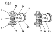
- a damper 22 includes at least one piston 23 and a cylinder 24, wherein one end of the piston 23 is pivotally mounted via a pin 8 eccentrically on the axis of rotation 7. The other end of the piston 23 dips into the cylinder 24.
- One end of the cylinder 24 is also pivotally attached to or in the damper mount 25.
- the damper mount 25 is fastened in the bearing block 20 or on the screw-on plate 21 by means of a closure 27.
- the damper 22 may be provided with an opening and / or damping function, which causes a speed reduction in one of the end positions.
- the damper 22 may also be equipped with an opening or closing control, whereby the door z. B. from the open position always returns to the closed position or what a Hold-open function is realized.
- the damper 22 may be provided with an air or oil damping, have an eddy current brake or a hysteresis.
- Each rotation or actuation of the door about the axis of rotation 7 of the belt 1 causes an extension of the piston 23 from the cylinder 24, wherein the damper 22 due to the eccentric arrangement on the axis of rotation 7 moves out of the longitudinal axis XX.
- two dampers 22 are arranged vertically one above the other in the bearing block 20. But it can also be just a damper 22 or depending on the space a plurality of dampers 22 may be arranged. Alternatively, the dampers 22 may also be arranged side by side, which makes the band 1 thicker in dimension.
- the band 1 in this embodiment is designed as a swing door hinge, in which the door 11 can be opened on both sides. Any mechanical opening limitation on the axis of rotation 7 can prevent the dampers 22 from being damaged.
- This band 1 can also be used as a normal band for doors with stop, with a mechanical opening limitation can also be provided for this application.
- the axis of rotation 7 may be constructed in one or more parts.
- the axis of rotation 7 is made in one piece, wherein the axis of rotation 7 recesses for receiving the piston 23 has.
- FIG. 4 is again the gap 55 between the clamping plates 3, 4 and the bearing block 20 can be seen. Due to the rounded front edge of the bearing block 20 a crushing and Einklemmgefahr is minimized.
- a locking device in a swing door has the function of keeping the door in a specific open position, z. B. at 90 ° door opening angle and / or to close the door safely and to position in the zero position.
- the latching device comprises at least one cam 30 which is arranged on the axis of rotation 7 and a counter-pressure device, for. B. in the form of a roller 33 which is pressed by a spring 36 against the cam 30.
- the cam 30 cooperates with a roller 33, wherein the surfaces of cam 30 and roller 33 roll on each other during the operation of the belt 1.
- a recess 31 is arranged, which at least partially can receive a circular section of the roller 33.
- one or more recesses 32 can be arranged on the circumference of the cam 30, which also interact with the roller 33.
- the cam 30 may be constructed with the rotation axis 7 one or more parts.
- the cam 30 is formed integrally with the axis of rotation 7, wherein the cam 30 is integrally connected to the axis of rotation 7.
- the roller 33 is rotatably supported by a bolt, not shown, on a roller piston 34.
- the roller piston 34 in turn is arranged to be movable in the axial direction in a control cylinder 35. In the axial direction acts against the roller piston 34, a force, so that the roller 33 is pressed against the cam 30.
- the force can be applied by a spring 36 or hydraulically or pneumatically.
- the roller piston 34 is formed on one side as a pot into which the spring 36 at least partially engages and is guided.
- the spring 36 is supported on a closure 27, which is arranged and fixed on or in the mounting plate 21.
- the roller 33 In the zero position of the door, the roller 33 is located in the recess 31 of the cam 30.
- the clamping plates 3, 4 rotate with the door about the axis of rotation 7
- the axis of rotation 7 Since the axis of rotation 7 is arranged rotationally fixed by fastening means within the first clamping plate 3, the axis of rotation rotates within the bearing block 20, wherein the cam 30 rolls with its surface on the surface of the rotating roller 33.
- the roller 33 is pressed with the roller piston 34 against the spring 36 and comes out of the recess 31 during this rotational movement.
- a further recess 32 may be arranged at a 90 ° angle to the recess 31, so that the door in this intermediate position stop.
- These or more locking recesses 32 can be distributed in any extent on the cam 30, depending on the intermediate positions in which the door should remain open. If the door is closed with momentum, the axis of rotation 7 rotates with the cam 30 until the roller 30 returns to the recess 31. In this case, depending on the size of the spring force, the cam 30 with the recess 31 are repeatedly moved back and forth, wherein the roller 33 passes over the recess 31 of the cam 30 until the torque from the spring force and the force of the damper 22 is greater , as the remaining torque of the door.
- the damper or dampers 22 according to this second embodiment are arranged substantially in a damper cartridge 41, which has a stop 42 with a stop surface 43, wherein the stop surface 43 cooperates with a cam 40.
- a respective damper cartridge is arranged above and below the latching device. It may also be possible, depending on the application, to arrange only a damper cartridge in addition to the locking device.
- the arrangement of the damper cartridges 41 on the axis of rotation 7 may be arbitrary.
- the damper cartridge 41 can accommodate at least one or more dampers 22, wherein the cylinders 24 of the damper are encapsulated in a preferred embodiment with plastic or sheathed.
- a stop 42 is connected to the piston 23 of the damper 22.
- the stop 42 may have a flat, convex or concave abutment surface 43, which cooperates with the surface of the cam 40.
- the geometry of the stop surface 43 depends on the desired damping effect. Since the dampers 22 work as a closing damper, the stop 42 must be pressed against the cam 40 against the damping force. This is achieved by one or more springs 45, which press the stop surface 43 against the surface of the cam 40.
- the roller 33 of the locking device engages in the recess 31 of the cam 30 on. So that the door does not oscillate continuously until the kinetic energy of the door is consumed, the damper or dampens the rotational movement of the door, so that the roller 33 of the locking device no longer comes out of the recess 31 of the cam 30 out. The door thus remains in its zero position.
- the arrangement of the dampers 22 in a damper cartridge 41 is in Fig. 8 shown again.
- three dampers 22 are shown with their pistons 23 and cylinders 24, which are inserted into a damper cartridge 41.
- the connection between the stop 42 and the dampers 22 is made via pins 8.
- springs 45 are arranged, which can extend the piston 23 from the cylinders 24.
- an overload protection 44 is arranged on the front side of the stop 42, the stop surface 43 cooperates with the cam 40.
- the overload protection 44 prevents destruction of the damper 22, if the door 11 is operated with too much force.
- the overload protection 44 is formed in this embodiment as a leaf spring, which deforms when overloaded.
- the arrangement of the damper 22 in a damper cartridge 41 has the advantage that they can be replaced as a module without much installation and adjustment effort. Furthermore, the damper cartridges 41 can be assembled by door size and weight, with z. For example, for a small door only one damper cartridge 41 with two dampers 22 is used, and for a large door a damper cartridge 41 with four dampers 22 is used.
- the tape can thus be variably equipped for a variety of different sized and heavy doors, for which no specialist personnel is needed.
- FIG Fig. 9 Another embodiment of an arrangement of the dampers 22 in a damper cartridge 41 is shown in FIG Fig. 9 shown.
- This embodiment shows three dampers 22 with their pistons 23 and cylinders 24, which are inserted into a damper cartridge 41. Again, the connection between the stopper 42 and the dampers 22 is made by pins 8. Between the stop 42 and the damper cartridge 41 springs 45 are arranged, which can extend the piston 23 from the cylinders 24. Side of the stop 42 sliders 48 are arranged, which provide a low-friction guidance.
- the overload protection 44 is arranged behind the cylinder 24, between a baffle plate 46 and a shutter 47 in this embodiment. This embodiment shows an overload protection made of plastic, which deforms elastically. At the baffle plate 46, the cylinder 24 is based with its bottom. The closure 47 closes the damper cartridge 41. It is formed by the stop 42, mounted with the dampers 22 summarized in the damper cartridge 41 a finished damper magazine 49, which can be used in a different design configuration in
- the volume 1 after FIG. 10 is pivoted to 90o to the side, so that the front side of an edged bearing block 20 is visible.
- a cap 29 which in this embodiment surrounds the bearing block U-shaped from three sides, a cladding 51 can be dismantled, behind which at least one damper insert 50 is visible.
- This damper insert 50 is designed as an opening for inserting or removing a complete damper magazine 49.
- the band can be provided with different dampers with a few simple steps, so that an exchange of damaged dampers or adaptation to different requirements without specialist personnel is possible.
- the bearing block 20 has an edged contour, there is a risk of injury during the rotational movement of the door when a finger enters the gap 55 between the bearing block 20 and wing hinge part 2.
- the gap 55 is covered with a stop 52, which according to FIG. 11 consists essentially of a carrier 53 with a buffer 54.
- the buffer 54 is formed at an acute angle of an elastic material and is arranged with its tip to the bearing block 20 back.
- the stop 52 may consist of a combination of materials, wherein the carrier 53 may consist of a hard material such as plastic or metal, and the buffer 54 of a soft material, such as rubber or plastic.
Landscapes
- Closing And Opening Devices For Wings, And Checks For Wings (AREA)
- Hinges (AREA)
- Wing Frames And Configurations (AREA)
Description
- Die Erfindung betrifft ein Band für eine drehbar gelagerte Tür, umfassend ein festes Bandteil, einem um das feste Bandteil schwenkbaren Flügelbandteil und einer das feste Bandteil und das Flügelbandteil durchfassenden Drehachse, wobei die Drehachse mit einer Öffnungs- und/oder Schließdämpfung zusammenwirkt, die durch mehrere Dämpfer gebildet wird, die mit der Drehachse zusammenwirken.
- Zur Beeinflussung des Öffnungs- und Schließverhalten einer Drehflügeltür werden üblicherweise Türschließer verwendet, die im Boden unsichtbar eingebaut werden können oder an der Türzarge sichtbar befestigt werden. Mit diesen Türschließern kann eine einstellbare Dämpfung in der Endlage des Öffnens oder Schließens realisiert werden. Die Türschließer können aber auch Funktionen wie ein Offenhalten oder ein automatisches Schließen ermöglichen. Üblicherweise ist der Großteil dieser Türschließer nur für ein Öffnen der Drehflügeltür in eine Richtung geeignet. Bei Pendeltüren sind besondere Maßnahmen erforderlich, mit denen die Funktionen des Türschließers in beide Richtungen ermöglicht werden können. Ein besonderer Nachteil ist dabei, dass insbesondere bei Türen aus Glas die Türschließer entweder sichtbar sind, oder sehr aufwändig im Boden angeordnet werden müssen, da hierzu der Boden aufgestemmt werden muss, um Platz für den Bodentürschließer zu schaffen.
- Die
GB 396,889 - Die
WO 2007/12554A1 - Mit diesem Stand der Technik ist ein leichter Austausch der Dämpfungselemente nicht zu erreichen.
- Aufgabe der Erfindung ist es, eine drehbar gelagerte Tür mit Bändern zu schaffen, die diese Nachteile nicht aufweist.
- Die Erfindung löst die gestellte Aufgabe durch die Lehre nach Anspruch 1. Weitere vorteilhafte Ausgestaltungsmerkmale der Erfindung sind durch die Unteransprüche gekennzeichnet.
- Erfindungsgemäß wird die Öffnungs- und/oder Schließdämpfung des Bandes durch mehrere Dämpfer gebildet, die mit der Drehachse zusammenwirken. Die Dämpfer dämpfen die Drehbewegung der Tür durch Aufzehren der kinetischen Energie.
- Die Anordnung der Dämpfer innerhalb einer Dämpferpatrone ermöglicht die leichte Austauschbarkeit dieses Bauteiles. Weiterhin kann die Dämpferpatrone gestuft nach der gewünschten Dämpfungswirkung mit einem oder mehreren Dämpfern bestückt sein. Für den Monteur oder Endbenutzer ergibt sich der Vorteil, dass keine Spezialwerkzeuge oder Fachkenntnis nötig sind, um einen beschädigten Dämpfer auszutauschen oder mit einer höheren Dämpfungswirkung den Gegebenheiten anzupassen. Für den Hersteller des Bandes ergibt sich der Vorteil der kostengünstigen Herstellung, da ein Band ohne konstruktive Änderung mit verschiedenen Dämpfern ausgestattet werden kann, wodurch das Band für verschiedene Türbreiten und Türgewichte einsetzbar ist. Lediglich die Dämpfer sind auf die Türgröße anzupassen.
- In bevorzugter Ausführungsform weist die Dämpfer einen Kolben auf, der innerhalb eines Zylinders ein Fluid oder Gas zwischen zwei Druckräumen bewegt. Damit kann ein sehr kleiner und wirkungsvoller Dämpfer geschaffen werden, der aufgrund seiner Baugröße leicht in die Abmessungen eines Bandes integriert werden kann.
- Besonders vorteilhaft ist es, wenn die Dämpferpatrone einen Anschlag aufweist, der mit der Drehachse zusammenwirkt. Dies hat den Vorteil, dass nicht jeder Dämpfer, trotz Integration in eine Dämpferpatrone, separat und aufwändig an der Drehachse befestigt werden muss. Dabei kann der Anschlag mit einer Nocke zusammenwirken, die auf der Drehachse angeordnet ist. Über die Nocke wird wiederum die notwendige Exzentrizität, und damit das Drehmoment bzw. der Dämpfungsweg eingestellt.
- Der Anschlag kann eine ebene, konvexe oder konkave Anschlagfläche aufweisen, wobei die Gestaltung der Anschlagfläche wiederum die Exzentrizität verstärken oder schwächen kann. Es ergibt sich über die Gestaltung der Anschlagfläche eine zusätzliche Variable, um ein einziges Band mit verschiedenen Dämpfern bzw. Dämpferpatronen für verschiedene Anwendungen zu kombinieren.
- In bevorzugter Ausgestaltung sind die Dämpfer als Schließdämpfer gestaltet, die beim Zusammendrücken die kinetische Energie aufzehren. Hierzu muss eine Gegenkraft aufgebracht werden, so dass der Anschlag permanent gegen die Nocke gedrückt wird. Eine preiswerte Möglichkeit ist dabei, die Dämpferpatrone mit einer Druckfeder auszustatten, die den Anschlag gegen die Nocke drückt. Damit ist sichergestellt, dass Anschlag und Nocke permanent in Kontakt sind.
- Zur Schaffung eines Pendeltürbandes ist in vorteilhafter Ausführungsform vorgesehen, dass die Offen- und Schließhaltefunktion durch eine an der Drehachse angeordnete Rastvorrichtung erzeugt wird. Mit der Rastvorrichtung wird die Möglichkeit geschaffen, die Tür in vorbestimmten Positionen zu halten, so dass z. B. durch Windlasten die Tür nicht hin- und herschwingt. Auch ist es möglich, mit der Rastvorrichtung die Tür z. B. bei einem Öffnungswinkel von 90° offen zu halten, ohne das eine mögliche Schließfunktion die Tür immer in die Null- oder Geschlossenstellung fährt.
- Eine preiswerte konstruktive Gestaltung der Erfindung sieht vor, dass die Rastvorrichtung durch eine an der Drehachse angeordnete Nocke mit einer Vertiefung gebildet wird, die mit einer kraftbeaufschlagten Rolle zusammenwirkt. Diese Ausführungsform bietet den Vorteil, dass preiswerte Standardbauteile verwendet werden können.
- Die Anordnung der Öffnungs- und Schließdämpfung ober- und/oder unterhalb der Rastvorrichtung an der Drehachse ermöglicht eine kompakte Bauweise des Bandes.
- Eine weitere Verbesserung ergibt sich, wenn an dem Anschlag ein Überlastschutz angeordnet ist. Damit lassen sich Beschädigungen oder Zerstörungen der Dämpfer vermeiden. In bevorzugter Ausführungsform ist der Überlastschutz als Blattfeder ausgebildet, die sich bei zu hohen Kräften verformt.
- Weitere Vorteile und Ausführungsformen der Erfindung werden nachfolgend anhand mehrerer schematisch dargestellter Ausführungsbeispiele näher erläutert. Dabei wird für gleiche Bauteile das gleiche Bezugszeichen verwendet.
- Es zeigen:
- Figur 1:
- eine Tür mit Bändern,
- Figur 2:
- eine perspektivische Darstellung des Gelenkbandes,
- Figur 3:
- eine Schnittdarstellung des Gelenkbandes nach einer ersten Ausführungsform,
- Figur 4:
- einen Teilschnitt des Gelenkbandes nach einer ersten Ausführungsform,
- Figur 5:
- eine perspektivische Ansicht einer zweiten Ausführungsform,
- Figur 6:
- eine perspektivische Ansicht einer zweiten Ausführungsform,
- Figur 7:
- eine Schnittdarstellung der zweiten Ausführungsform,
- Figur 8:
- eine perspektivische Ansicht einer Dämpferpatrone,
- Figur 9:
- ein weiteres Ausführungsbeispiel einer Dämpferpatrone,
- Figur 10:
- eine weitere Ausführungsform eines Gelenkbandes,
- Figur 11:
- eine Detaildarstellung eines Anschlages.
- In
Figur 1 wird eine Tür 11 dargestellt, die an einer Wand 12 mittels eines Bandes 1 angeordnet ist. Dabei kann die Tür 11 ausschließlich mit einem einzigen Band 1 an der Wand 12, einer Zarge oder einem Seitenteil befestigt werden. Alternativ kann die Tür 11 auch an einem Gelenkband 10 und an einem Band 1 drehbar gelagert sein. - Eine weitere Alternative ergibt sich dann, wenn ein bestehender Türschließer durch ein Band 1 ersetzt werden soll. Dann ist die Tür 11 an zwei bereits bestehenden Gelenkbändern 10 drehbar gelagert, zwischen denen das Band 1 angeordnet ist.
- Weiterhin kann die Tür 11 als Pendeltür ausgebildet sein, so dass auch die Gelenkbänder 10 und das Band 1 als Pendeltürbänder ausgebildet sind. Die Tür 11 kann aber auch mittels zwei Funktionsbändem 1 an einer Wand 12, Zarge oder Seitenteil befestigt werden.
- Insbesondere bei einer Glastür ermöglicht die Verwendung der Erfindung ein transparentes Design einer Ganzglasanlage, das mit herkömmlichen Türschließern nicht realisiert werden kann.
- Das Band 1 gemäß
Figur 2 weist ein festes Bandteil auf, das hier als Lagerbock 20 bezeichnet wird und ein Flügelbandteil 2. An dem Lagerbock 20 ist eine Anschraubplatte 21 befestigt, mit der das Band 1 an eine nicht dargestellte Wand oder Wandkonstruktion befestigt wird. Statt des Lagerbockes 20 kann das Band 1 auch einen weiteren Bandlappen zur Befestigung an einer Glasscheibe oder an ein Wandelement aufweisen. - Das Flügelbandteil 2 umfasst mindestens eine erste Klemmplatte 3 und eine zweite Klemmplatte 4, die mittels Befestigungsmittel 5 ein nicht dargestelltes Türelement oder eine Glastür klemmend haltern. Zwischen den Klemmplatten 3, 4 und einer Glasscheibe sind Dicht- und/oder Dämpfungsplatten 6 angeordnet, um das Türblatt aus Holz oder Glas möglichst schonend zu umfassen. Beidseitig des Lagerbockes 20 können dekorative Abdeckkappen 29 angeordnet sein. Zwischen dem Lagerbock 20 und den Klemmplatten 3, 4 ist ein Spalt 55 angeordnet, damit sich die Bauteile bei der Betätigung der Tür nicht berühren. Um Verletzungen zu vermeiden, ist die Stirnseite des Lagerbockes 20, die dem Spalt 55 zugewandt ist, gerundet.
- Wie in
Figur 3 undFigur 4 dargestellt, ist eine Drehachse 7 drehfest an der ersten Klemmplatte 3 befestigt. Die Drehachse 7 bildet dabei die Drehoder Schwenkachse des Bandes 1. Die Drehachse 7 wird dabei mit Zapfen 7a an der ersten Klemmplatte 3 befestigt und mit Befestigungsmitteln wie z. B. verstemmten Nieten oder Schrauben drehfest fixiert. Über die Verschlüsse 9 wird die Drehachse 7 im Lagerbock 20 fixiert und gelagert. Das Flügelbandteil 2 mit der Drehachse 7 dreht sich beim Öffnen der Tür um die Drehachse 7, wobei der Lagerbock 20 an einer Wand, Zarge oder einem festen Seitenteil fixiert ist. Ein Dämpfer 22 umfasst mindestens einen Kolben 23 und einen Zylinder 24, wobei ein Ende des Kolbens 23 über einen Stift 8 exzentrisch an der Drehachse 7 drehgelenkig befestigt ist. Das andere Ende des Kolbens 23 taucht in den Zylinder 24 ein. Ein Ende des Zylinders 24 ist ebenfalls drehgelenkig an oder in der Dämpferaufnahme 25 befestigt. Die Dämpferaufnahme 25 wird mittels eines Verschlusses 27 im Lagerbock 20 bzw. an der Anschraubplatte 21 befestigt. Bei einem Verdrehen der Drehachse 7 schwenkt der exzentrisch gelagerte Stift 8 um die Drehachse des Bandes 1, so dass sich der Kolben 23 aus dem Zylinder 24 herausbewegt und der Dämpfer 22 aus der Längsachse = Nulllage des Gelenkbandes X-X heraus dreht. - Der Dämpfer 22 kann mit einer Öffnungs- und/oder Dämpfungsfunktion ausgestattet sein, die eine Geschwindigkeitsreduktion in eine der Endlagen bewirkt. Der Dämpfer 22 kann aber auch mit einer Öffnungs- oder Schließregelung ausgestattet sein, wodurch die Tür z. B. aus der Offenstellung immer in die Geschlossenstellung zurückfährt oder womit eine Offenhaltefunktion realisiert wird. Hierzu kann, je nach Anwendungsfall, der Dämpfer 22 mit einer Luft- oder Öldämpfung versehen werden, eine Wirbelstrombremse oder eine Hysteresebremse aufweisen.
- In einer bevorzugten Ausführungsform sind die Dämpfer 22 als Schließdämpfer ausgelegt, so dass die Tür beim Bewegen in die Nulllage bzw. beim Schließen gedämpft wird. Dazu sind die Dämpfer 22 so konzipiert, dass beim Ausfahren der Kolben 23 aus dem Zylinder 24 nur eine geringe Kraft aufgebracht wird, so dass der Benutzer die Tür leicht öffnen kann.
- Beim Schließen der Tür fahren die Kolben 23 in den Zylinder 24 ein und erzeugen eine große Kraft, so dass die Tür in der Nulllage bzw. beim Schließen gedämpft wird. Dies hat den Effekt, dass bei einer normalen Tür, die gegen einen Anschlag oder eine Dichtung fährt, die Tür nicht beschädigt werden kann. Bei einer Pendeltür wird dadurch vermieden, dass diese mit Schwung in der anderen Richtung öffnet und hin und her pendelt. In dieser bevorzugten Ausführungsform sind die Dämpfer 22 mit einem Fluid oder Gas gefüllt, das bei der Betätigung des Dämpfers zwischen zwei Druckräumen hin und her bewegt wird. Bei Verwendung von Ventilen oder besonders gestalteten Dichtungen wird erreicht, dass nur in eine Richtung - hier beim Ausziehen des Kolbens 23 aus dem Zylinder 24 - das Fluid oder Gas mit geringem Widerstand zwischen den Druckräumen verschoben wird, während in der anderen Richtung ein großer Widerstand erzeugt wird.
- Jedes Drehen oder Betätigen der Tür um die Drehachse 7 des Bandes 1 bewirkt dabei ein Ausfahren des Kolbens 23 aus dem Zylinder 24, wobei sich der Dämpfer 22 aufgrund der exzentrischen Anordnung an der Drehachse 7 aus der Längsachse X-X herausbewegt. In diesem Ausführungsbeispiel sind zwei Dämpfer 22 vertikal übereinander in dem Lagerbock 20 angeordnet. Es können aber auch nur ein Dämpfer 22 oder je nach Platzverhältnis mehrere Dämpfer 22 angeordnet sein. Alternativ können die Dämpfer 22 auch nebeneinander angeordnet sein, was das Band 1 aber in den Abmessungen dicker macht.
- Das Band 1 in diesem Ausführungsbeispiel ist als Pendeltürband ausgestaltet, bei dem die Tür 11 zu beiden Seiten geöffnet werden kann. Über eine beliebige mechanische Öffnungsbegrenzung an der Drehachse 7 kann vermieden werden, dass die Dämpfer 22 beschädigt werden. Dieses Band 1 kann auch als normales Band für Türen mit Anschlag verwendet werden, wobei auch für diesen Anwendungsfall eine mechanische Öffnungsbegrenzung vorgesehen werden kann.
- Die Drehachse 7 kann ein- oder mehrteilig aufgebaut sein. In diesem Ausführungsbeispiel ist die Drehachse 7 einteilig ausgeführt, wobei die Drehachse 7 Vertiefungen zur Aufnahme der Kolben 23 aufweist. In
Figur 4 ist wieder der Spalt 55 zwischen den Klemmplatten 3, 4 und dem Lagerbock 20 zu erkennen. Durch die gerundete Stirnkante des Lagerbockes 20 wird eine Quetsch- und Einklemmgefahr minimiert. - Im zweiten Ausführungsbeispiel nach den
Fig. 5 ,6 und7 wird eine Rastvorrichtung mit der zuvor beschriebenen Dämpfungsvorrichtung kombiniert. Eine Rastvorrichtung bei einem Pendeltürband hat die Funktion, die Tür in einer bestimmten Offenstellung zu halten, z. B. bei 90° Türöffnungswinkel und/oder die Tür sicher zu schließen und in der Nulllage zu positionieren. Hierzu umfasst die Rastvorrichtung mindestens eine Nocke 30, die auf der Drehachse 7 angeordnet ist und eine Gegendruckvorrichtung, z. B. in Form einer Rolle 33, die durch eine Feder 36 gegen die Nocke 30 gedrückt wird. In diesem Ausführungsbeispiel wirkt die Nocke 30 mit einer Rolle 33 zusammen, wobei sich die Oberflächen von Nocke 30 und Rolle 33 bei der Betätigung des Bandes 1 aufeinander abwälzen. In der Nocke 30 ist eine Vertiefung 31 angeordnet, die wenigstens teilweise einen Kreisabschnitt der Rolle 33 aufnehmen kann. Weiterhin kann auf dem Umfang der Nocke 30 noch eine oder mehrere Ausnehmungen 32 angeordnet sein, die ebenfalls mit der Rolle 33 zusammenwirken. - Die Nocke 30 kann mit der Drehachse 7 ein- oder mehrteilig aufgebaut sein. In diesem Ausführungsbeispiel ist die Nocke 30 mit der Drehachse 7 einteilig ausgeführt, wobei die Nocke 30 einstückig mit der Drehachse 7 verbunden ist.
- Die Rolle 33 ist drehbar mittels eines nicht dargestellten Bolzens an einem Rollenkolben 34 gelagert. Der Rollenkolben 34 wiederum ist in axialer Richtung beweglich in einem Stellzylinder 35 angeordnet. In axialer Richtung wirkt gegen den Rollenkolben 34 eine Kraft, so dass die Rolle 33 gegen die Nocke 30 gedrückt wird. Die Kraft kann durch eine Feder 36 oder hydraulisch oder pneumatisch aufgebracht werden. In diesem Ausführungsbeispiel ist der Rollenkolben 34 einseitig als Topf ausgebildet, in den die Feder 36 zumindest teilweise eingreift und geführt wird. Die Feder 36 stützt sich dabei an einem Verschluss 27 ab, der an oder in der Anschraubplatte 21 angeordnet und befestigt wird.
- In der Nullstellung der Tür liegt die Rolle 33 in der Vertiefung 31 der Nocke 30. Beim Öffnen der Tür drehen sich, da der Lagerbock 20 über die Anschraubplatte 21 an einer Wand befestigt ist, die Klemmplatten 3, 4 mit der Tür um die Drehachse 7 des Bandes 1. Da die Drehachse 7 über Befestigungsmittel innerhalb der ersten Klemmplatte 3 drehfest angeordnet ist, dreht sich die Drehachse innerhalb des Lagerbockes 20, wobei die Nocke 30 sich mit ihrer Oberfläche an der Oberfläche der drehend angeordneten Rolle 33 abwälzt. Die Rolle 33 wird dabei mit dem Rollenkolben 34 gegen die Feder 36 gedrückt und kommt bei dieser Drehbewegung aus der Vertiefung 31 heraus. Eine weitere Ausnehmung 32 kann in einem 90°-Winkel zur Vertiefung 31 angeordnet sein, so dass die Tür in dieser Zwischenposition stehen bleibt. Diese oder auch mehrere Rastausnehmungen 32 können in beliebigem Umfang auf der Nocke 30 verteilt angeordnet werden, je nachdem, in welchen Zwischenstellungen die Tür geöffnet bleiben soll. Wird die Tür mit Schwung geschlossen, dreht sich die Drehachse 7 mit der Nocke 30, bis die Rolle 30 wieder in die Vertiefung 31 gelangt. Dabei kann, je nach Größe der Federkraft, die Nocke 30 mit der Vertiefung 31 mehrmals hin und her bewegt werden, wobei die Rolle 33 dabei die Vertiefung 31 der Nocke 30 überfährt, bis das Drehmoment aus der Federkraft und der Kraft des Dämpfers 22 größer ist, als das verbleibende Drehmoment der Tür.
- Der oder die Dämpfer 22 nach diesem zweiten Ausführungsbeispiel sind im Wesentlichen in einer Dämpferpatrone 41 angeordnet, die einen Anschlag 42 mit einer Anschlagfläche 43 aufweist, wobei die Anschlagfläche 43 mit einer Nocke 40 zusammenwirkt. In diesem Ausführungsbeispiel ist je eine Dämpferpatrone oberhalb und unterhalb der Rastvorrichtung angeordnet. Es kann je nach Anwendungsfall auch möglich sein, nur eine Dämpferpatrone neben der Rastvorrichtung anzuordnen. Auch die Anordnung der Dämpferpatronen 41 an der Drehachse 7 kann beliebig sein. Die Dämpferpatrone 41 kann mindestens einen oder mehrere Dämpfer 22 aufnehmen, wobei die Zylinder 24 der Dämpfer in bevorzugter Ausführungsform mit Kunststoff umspritzt bzw. ummantelt sind. Ein Anschlag 42 ist mit den Kolben 23 der Dämpfer 22 verbunden. Der Anschlag 42 kann eine ebene, konvexe oder konkave Anschlagfläche 43 aufweisen, die mit der Oberfläche der Nocke 40 zusammenwirkt. Die Geometrie der Anschlagfläche 43 hängt dabei von der gewünschten Dämpfungswirkung ab. Da die Dämpfer 22 als Schließdämpfer arbeiten, muss gegen die Dämpfungskraft der Anschlag 42 gegen den Nocken 40 gedrückt werden. Dies wird durch eine oder mehrere Federn 45 erreicht, die die Anschlagfläche 43 gegen die Oberfläche der Nocke 40 drücken. Bei einem Schließen der Tür rastet die Rolle 33 der Rastvorrichtung in die Vertiefung 31 der Nocke 30 ein. Damit die Tür nicht dauernd hin und her schwingt, bis die kinetische Energie der Tür aufgezehrt ist, dämpft der oder die Dämpfer die Drehbewegung der Tür ab, so dass die Rolle 33 der Rastvorrichtung nicht mehr aus der Vertiefung der 31 der Nocke 30 heraus kommt. Die Tür verbleibt damit in ihrer Nulllage.
- Die Anordnung der Dämpfer 22 in einer Dämpferpatrone 41 wird in
Fig. 8 noch einmal dargestellt. In diesem Ausführungsbeispiel sind drei Dämpfer 22 mit ihren Kolben 23 und Zylindern 24 dargestellt, die in eine Dämpferpatrone 41 eingesteckt werden. Die Verbindung zwischen dem Anschlag 42 und den Dämpfern 22 wird über Stifte 8 hergestellt. Zwischen dem Anschlag 42 und der Dämpferpatrone 41 sind Federn 45 angeordnet, die die Kolben 23 aus den Zylindern 24 ausfahren lassen. In diesem Ausführungsbeispiel ist ein Überlastschutz 44 stirnseitig auf dem Anschlag 42 angeordnet, dessen Anschlagfläche 43 mit der Nocke 40 zusammenwirkt. Der Überlastschutz 44 verhindert eine Zerstörung der Dämpfer 22, falls die Tür 11 mit zu großer Kraft betätigt wird. Der Überlastschutz 44 ist in diesem Ausführungsbeispiel als Blattfeder ausgebildet, die sich bei Überbelastung verformt. - Die Anordnung der Dämpfer 22 in einer Dämpferpatrone 41 hat den Vorteil, dass ohne großen Montage- und Justieraufwand diese als Modul ausgetauscht werden können. Weiterhin können die Dämpferpatronen 41 nach Türgröße und Gewicht zusammengestellt werden, wobei z. B. für eine kleine Tür nur eine Dämpferpatrone 41 mit zwei Dämpfern 22 verwendet wird, und für eine große Tür eine Dämpferpatrone 41 mit vier Dämpfern 22 verwendet wird. Das Band kann damit für eine Vielzahl von unterschiedlich großen und schweren Türen variabel bestückt werden, wozu kein Fachpersonal nötig ist.
- Ein weiteres Ausführungsbeispiel einer Anordnung der Dämpfer 22 in einer Dämpferpatrone 41 wird in
Fig. 9 dargestellt. Dieses Ausführungsbeispiel zeigt drei Dämpfer 22 mit ihren Kolben 23 und Zylindern 24, die in eine Dämpferpatrone 41 eingesteckt werden. Auch hier wird die Verbindung zwischen dem Anschlag 42 und den Dämpfern 22 über Stifte 8 hergestellt. Zwischen dem Anschlag 42 und der Dämpferpatrone 41 sind Federn 45 angeordnet, die die Kolben 23 aus den Zylindern 24 ausfahren lassen. Seitlich am Anschlag 42 sind Gleiter 48 angeordnet, die für eine reibungsarme Führung sorgen. Der Überlastschutz 44 ist bei diesem Ausführungsbeispiel hinter dem Zylinder 24, zwischen einer Prallplatte 46 und einem Verschluss 47 angeordnet. Dieses Ausführungsbeispiel zeigt einen Überlastschutz aus Kunststoff, der sich elastisch verformt. An der Prallplatte 46 stützen sich die Zylinder 24 mit ihrem Boden ab. Der Verschluss 47 verschließt die Dämpferpatrone 41. Es entsteht durch den Anschlag 42, montiert mit den in der Dämpferpatrone 41 zusammengefassten Dämpfern 22 ein fertiges Dämpfermagazin 49, das in verschiedener Ausführungskonfiguration in ein Band 1 eingesetzt werden kann. - Das Band 1 nach
Figur 10 ist um 90o zur Seite verschwenkt, so dass die Stirnseite eines kantig gestalteten Lagerbockes 20 sichtbar wird. Nach Entfernen einer Abdeckkappe 29, die in diesem Ausführungsbeispiel den Lagerbock u-förmig von drei Seiten umschließt, kann eine Verkleidung 51 demontiert werden, hinter der mindestens ein Dämpfereinschub 50 sichtbar wird. Dieser Dämpfereinschub 50 ist als Öffnung zum Einsetzen bzw. Entfernen eines kompletten Dämpfermagazins 49 gestaltet. Dadurch kann mit wenigen Handgriffen das Band mit unterschiedlichen Dämpfern versehen werden, so dass ein Austausch von beschädigten Dämpfern oder eine Anpassung an unterschiedliche Anforderungen ohne Fachpersonal möglich ist. - Da in diesem Ausführungsbeispiel der Lagerbock 20 eine kantige Kontur aufweist, besteht bei der Drehbewegung der Tür Verletzungsgefahr, wenn ein Finger in den Spalt 55 zwischen Lagerbock 20 und Flügelbandteil 2 hineinkommt. Um den Spalt 55 abzudecken, wird der Spalt 55 mit einem Anschlag 52 verkleidet, der nach Figur 11 im Wesentlichen aus einem Träger 53 mit einem Puffer 54 besteht. Der Puffer 54 ist spitzwinklig aus einem elastischen Material gestaltet und wird mit seiner Spitze zum Lagerbock 20 hin angeordnet. Damit wird der Spalt 55 verschlossen, so dass ein Hineingreifen nicht mehr möglich wird. Durch die geometrische Gestaltung des Puffers 54 und seines elastischen Verhaltens wird eine optisch vollständig geschlossene Bandoberfläche erzeugt. Der Anschlag 52 kann dabei aus einer Materialkombination von bestehen, wobei der Träger 53 aus einem harten Material wie z.B. Kunststoff oder Metall bestehen kann, und der Puffer 54 aus einem weichen Material, wie z.B. Gummi oder Kunststoff.
-
- 1
- Band
- 2
- Flügelbandteil
- 3
- erste Klemmplatte
- 4
- zweite Klemmplatte
- 5
- Befestigungsmittel
- 6
- Dicht- und/oder Dämpfungsplatten
- 7
- Drehachse
- 7a
- Zapfen
- 8
- Stift
- 9
- Verschluss
- 10
- Gelenkband
- 11
- Tür
- 12
- Wand
- 20
- Lagerbock
- 21
- Anschraubplatte
- 22
- Dämpfer
- 23
- Kolben
- 24
- Zylinder
- 25
- Dämpferaufnahme
- 27
- Verschluss
- 29
- Abdeckkappe
- 30
- Nocke
- 31
- Vertiefung
- 32
- Ausnehmung
- 33
- Rolle
- 34
- Rollenkolben
- 35
- Stellzylinder
- 36
- Feder
- 40
- Nocke
- 41
- Dämpferpatrone
- 42
- Anschlag
- 43
- Anschlagfläche
- 44
- Überlastschutz
- 45
- Rückstellfeder
- 46
- Prallplatte
- 47
- Verschluss
- 48
- Dämpfermagazin
- 50
- Dämpfereinschub
- 51
- Verkleidung
- 52
- Anschlag
- 53
- Träger
- 54
- Puffer
- 55
- Spalt
- X-X
- Längsachse des Gelenkbandes
Claims (14)
- Band für eine drehbar gelagerte Tür (11),• umfassenddadurch gekennzeichnet, dass- ein festes Bandteil,- ein um das feste Bandteil schwenkbares Flügelbandteil (2) und- eine das feste Bandteil und das Flügelbandteil (2) durchfassende Drehachse (7), die mit einer Offnungs- und/oder Schließdämpfung zusammenwirkt, die durch mehrere Dämpfer (22) gebildet wird,• die Dämpfer (22) innerhalb einer Dämpferpatrone (41) angeordnet sind.
- Band nach Anspruch 1, dadurch gekennzeichnet, dass jeder Dämpfer (22) einen Kolben (23) aufweist, der innerhalb eines Zylinders (24) ein Fluid oder Gas zwischen zwei Druckräumen bewegt.
- Band nach Anspruch 1, dadurch gekennzeichnet, dass die Dämpferpatrone (41) einen Anschlag (42) aufweist, der mit der Drehachse (7) zusammenwirkt.
- Band nach Anspruch 3, dadurch gekennzeichnet, dass der Anschlag (42) mit einer Nocke (40) zusammenwirkt, die auf der Drehachse (7) angeordnet ist.
- Band nach Anspruch 4, dadurch gekennzeichnet, dass der Anschlag (42) eine ebene, konvexe oder konkave Anschlagfläche (43) aufweist.
- Band nach Anspruch 4, dadurch gekennzeichnet, dass der Anschlag (42) gegen die Nocke (40) gedrückt wird.
- Band nach Anspruch 5, dadurch gekennzeichnet, dass eine Offenund Schließhaltefunktion durch eine an der Drehachse (7) angeordnete Rastvorrichtung erzeugt wird.
- Band nach Anspruch 7, dadurch gekennzeichnet, dass die Rastvorrichtung durch eine an der Drehachse (7) angeordnete Nocke (30) mit einer Vertiefung (31) gebildet wird, die mit einer kraftbeaufschlagten Rolle (33) zusammenwirkt.
- Band nach Anspruch 7, dadurch gekennzeichnet, dass die Öffnungsund Schließdämpfung ober- und/oder unterhalb der Rastvorrichtung an der Drehachse (7) angeordnet ist.
- Band nach Anspruch 4, dadurch gekennzeichnet, dass an dem Anschlag (42) ein Überlastschutz (44) angeordnet ist.
- Band nach Anspruch 10, dadurch gekennzeichnet, dass der Überlastschutz (44) als Blattfeder oder als Kunststoffbauteil ausgebildet ist.
- Band nach Anspruch 1, dadurch gekennzeichnet, dass der Spalt (55) zwischen einem Lagerbock (20) und dem Flügelbandteil (2) mit einem Anschlag (52) verkleidet wird.
- Band nach Anspruch 12, dadurch gekennzeichnet, dass der Anschlag (52) aus einem Träger (53) mit einem Puffer (54) besteht.
- Band nach Anspruch 13, dadurch gekennzeichnet, dass der Puffer (54) spitzwinklig ausgebildet und mit seiner Spitze zum Lagerbock hin angeordnet ist.
Applications Claiming Priority (3)
| Application Number | Priority Date | Filing Date | Title |
|---|---|---|---|
| DE102009034740A DE102009034740A1 (de) | 2009-07-24 | 2009-07-24 | Drehbar gelagerte Tür mit einem Band |
| DE102010024109.1A DE102010024109B4 (de) | 2009-07-24 | 2010-06-17 | Band für eine drehbar gelagerte Tür |
| PCT/EP2010/004306 WO2011009557A2 (de) | 2009-07-24 | 2010-07-15 | Drehbar gelagerte tür mit einem band |
Publications (2)
| Publication Number | Publication Date |
|---|---|
| EP2456940A2 EP2456940A2 (de) | 2012-05-30 |
| EP2456940B1 true EP2456940B1 (de) | 2013-12-18 |
Family
ID=43384016
Family Applications (1)
| Application Number | Title | Priority Date | Filing Date |
|---|---|---|---|
| EP10735204.9A Active EP2456940B1 (de) | 2009-07-24 | 2010-07-15 | Band für eine drehbar gelagerte tür |
Country Status (10)
| Country | Link |
|---|---|
| US (1) | US9695621B2 (de) |
| EP (1) | EP2456940B1 (de) |
| JP (1) | JP2013500410A (de) |
| CN (1) | CN102472069A (de) |
| AU (1) | AU2010275796A1 (de) |
| CA (1) | CA2764407A1 (de) |
| DE (2) | DE102009034740A1 (de) |
| ES (1) | ES2450421T3 (de) |
| SG (1) | SG176684A1 (de) |
| WO (1) | WO2011009557A2 (de) |
Families Citing this family (31)
| Publication number | Priority date | Publication date | Assignee | Title |
|---|---|---|---|---|
| DE102009034742A1 (de) * | 2009-07-24 | 2011-02-03 | Dorma Gmbh + Co. Kg | Türschließer |
| DE102009034740A1 (de) * | 2009-07-24 | 2011-01-27 | Dorma Gmbh + Co. Kg | Drehbar gelagerte Tür mit einem Band |
| GB2479145A (en) * | 2010-03-29 | 2011-10-05 | Ingersoll Rand Security Technologies Ltd | Door closer having two springs |
| WO2012137042A1 (en) * | 2011-04-05 | 2012-10-11 | In & Tec S.R.L. | Hinge device for doors, shutters or the like |
| WO2012150481A1 (en) * | 2011-05-04 | 2012-11-08 | Ol.Mi S.R.L. | Hinge |
| ITVI20110124A1 (it) * | 2011-05-19 | 2012-11-20 | In & Tec Srl | Dispositivo a pistone per la chiusura automatica controllatadi porte, ante o similari |
| DE102011083259A1 (de) * | 2011-09-23 | 2013-03-28 | Beiersdorf Ag | Alkylamidothiazole, deren kosmetische oder dermatologische Verwendung sowie kosmetische oder dermatologische Zubereitungen mit einem Gehalt an solchen Alkylamidothiazolen |
| JP2013248922A (ja) * | 2012-05-30 | 2013-12-12 | Kyowa Sangyo Kk | 車両用サンバイザ |
| DE102013008211B4 (de) * | 2012-10-19 | 2021-05-06 | Gral Systeme Gmbh | Drehflügelbeschlag und Duschabtrennung |
| ITVI20130097A1 (it) * | 2013-04-12 | 2014-10-13 | In & Tec Srl | Cerniera per la movimentazione girevole controllata di una porta |
| ITVI20130100A1 (it) * | 2013-04-12 | 2014-10-13 | In & Tec Srl | Cerniera per la movimentazione girevole controllata di una porta |
| EA030833B1 (ru) * | 2013-04-12 | 2018-10-31 | Ин Энд Тек С.Р.Л. | Петля для регулируемого вращательного движения двери |
| CN104213791B (zh) * | 2013-05-29 | 2016-04-20 | 稳多企业股份有限公司 | 用于门的油压铰链缓冲装置 |
| DE102013110111A1 (de) | 2013-09-13 | 2015-04-02 | Hettich-Heinze Gmbh & Co. Kg | Dämpfungsvorrichtung |
| US9725940B2 (en) | 2014-07-24 | 2017-08-08 | Michael Lambright | Door hinge closing mechanism |
| GB2538039A (en) * | 2015-02-04 | 2016-11-09 | Kohler Mira Ltd | Hinge |
| US10428575B2 (en) * | 2017-03-24 | 2019-10-01 | The Boeing Company | Vented hinge assembly |
| IT201800003566A1 (it) * | 2018-03-14 | 2019-09-14 | Visottica Ind Spa | Cerniera elastica per occhiali e metodo di assemblaggio di detta cerniera |
| JP6769684B2 (ja) | 2018-04-25 | 2020-10-14 | スガツネ工業株式会社 | ヒンジ装置の取付け構造 |
| CN108756552A (zh) * | 2018-07-16 | 2018-11-06 | 佛山市远阳五金制品有限公司 | 一种90度自动回位阻尼合页 |
| TWI670409B (zh) * | 2018-08-22 | 2019-09-01 | 穩多企業股份有限公司 | 緩衝鉸鏈 |
| US11781359B2 (en) * | 2019-07-03 | 2023-10-10 | In & Tec S.R.L. | Small bulkiness hinge |
| AU2021271942C1 (en) * | 2020-05-11 | 2026-02-26 | Brolock Pty Ltd | A hinge |
| DE102020207128B3 (de) | 2020-06-08 | 2021-11-25 | Kermi Gmbh | Scharnier mit integrierter Anschlagdämpfung |
| DE102020125605A1 (de) * | 2020-09-30 | 2022-03-31 | Hettich-Oni Gmbh & Co. Kg | Mehrgelenkscharnier |
| US20240200383A1 (en) * | 2021-04-29 | 2024-06-20 | In & Tec S.R.L. | Hydraulic hinge for the controlled rotary movement of a door, a leaf or the like |
| CN113090150A (zh) * | 2021-04-30 | 2021-07-09 | 瑞高精密五金科技(惠州)有限公司 | 铰链 |
| US12171149B2 (en) | 2021-05-19 | 2024-12-24 | Christopher White | Foldable shovel |
| CN113622776B (zh) * | 2021-07-28 | 2024-09-03 | 箭牌家居集团股份有限公司 | 一种闭门器 |
| CN116025240A (zh) * | 2023-03-30 | 2023-04-28 | 箭牌家居集团股份有限公司 | 闭门器组件及淋浴房装置 |
| TWI873821B (zh) * | 2023-08-30 | 2025-02-21 | 鋼國工業股份有限公司 | 鉸鏈機構 |
Family Cites Families (47)
| Publication number | Priority date | Publication date | Assignee | Title |
|---|---|---|---|---|
| GB396889A (en) | 1932-05-11 | 1933-08-17 | James Garth Mitchell | Improvements relating to hinges |
| US3028619A (en) * | 1958-09-22 | 1962-04-10 | Schlage Lock Co | Hold open device for door closer |
| FR1237586A (fr) * | 1958-10-17 | 1960-07-29 | Fr Roderich Musfeldt | Dispositif de fermeture de porte se montant dans le sol |
| US3137888A (en) * | 1962-01-11 | 1964-06-23 | Bommer Spring Hinge Co Inc | Concealed overhead door closer |
| DE2924311A1 (de) * | 1979-06-15 | 1980-12-18 | Dorma Baubeschlag | Selbsttaetiger tuerschliesser |
| CA2062630C (en) * | 1992-01-13 | 1995-06-13 | Allen Riblett | Detent hinge |
| US5513420A (en) * | 1994-05-04 | 1996-05-07 | Tyler Refrigeration Corporation | Hinge assembly for refrigerated display cabinet |
| US5867869A (en) * | 1994-10-06 | 1999-02-09 | Chmi | Pressure hinge device for glass door or panel |
| US6161255A (en) * | 1998-08-06 | 2000-12-19 | Chmi | Pressure hinge device for glass door or panel |
| US6493904B1 (en) * | 2000-10-02 | 2002-12-17 | Heng Kuo Co., Ltd. | Door closer |
| US6526627B2 (en) * | 2000-12-05 | 2003-03-04 | Fanny Chiang | Hinge auto-return device for a glass door |
| US6442795B1 (en) * | 2001-01-16 | 2002-09-03 | Girefa Enterprise Co., Ltd. | Damper for a pivot door |
| US6560821B2 (en) * | 2001-02-09 | 2003-05-13 | The Group Legacy L.C. | Glass door hinge |
| US6481055B2 (en) * | 2001-04-10 | 2002-11-19 | Ko Ming Cheng | Pivotal device for a frameless glass door |
| US20030070255A1 (en) * | 2001-10-16 | 2003-04-17 | Jack Huang | Hydraulic door closer |
| US6519811B1 (en) * | 2002-04-09 | 2003-02-18 | Ko-Ming Cheng | Pivot hinge assembly for glass structure |
| US6704966B1 (en) * | 2002-10-30 | 2004-03-16 | Chin-Min Kao | Waterproof hinge structure for glass door |
| US6766561B1 (en) * | 2003-03-28 | 2004-07-27 | Ko-Ming Cheng | Frameless glass door hinge |
| US7114292B2 (en) * | 2003-04-11 | 2006-10-03 | Fanny Chiang | Adjustable automatic positioning hinge for glass doors |
| US7107723B2 (en) * | 2003-04-11 | 2006-09-19 | Fanny Chiang | Adjustable automatic positioning hinge for glass doors |
| US6925685B2 (en) * | 2003-09-08 | 2005-08-09 | Mei Li Chen | Angular adjustment arrangement of pivot hinge |
| US7010832B2 (en) * | 2003-10-02 | 2006-03-14 | Mei Li Chen | Angular adjustment arrangement of side pivot hinge |
| US7007341B2 (en) * | 2004-02-13 | 2006-03-07 | Fu Luong Hi-Tech Co., Ltd. | Door closer |
| US7316096B2 (en) * | 2004-06-30 | 2008-01-08 | Yale Security Inc. | Door operator |
| US20060021189A1 (en) * | 2004-07-30 | 2006-02-02 | Johnson Loring M | Door closer |
| DE102004041358B4 (de) * | 2004-08-25 | 2006-07-13 | Dorma Gmbh + Co. Kg | Obentürschließer |
| US7188390B2 (en) * | 2005-03-15 | 2007-03-13 | Ko-Ming Cheng | Adjustable hinge for a glass door |
| US7305797B2 (en) * | 2006-03-31 | 2007-12-11 | Fanny Chiang | Door-closing assembly of frameless glass door |
| US7305796B2 (en) * | 2006-03-31 | 2007-12-11 | Fanny Chiang | Door-closing assembly |
| EP2019895B1 (de) * | 2006-05-03 | 2010-10-13 | Dianora Gosio | SCHARNIERSTRUKTUR FÜR SELBST-SCHLIEßENDE TÜREN ODER DERGLEICHEN, INSBESONDERE GLASTÜREN ODER DERGLEICHEN, UND SOLCH EINE STRUKTUR ENTHALTENDE ANORDNUNG |
| ITVI20060131A1 (it) * | 2006-05-03 | 2007-11-04 | Gosio Dianora | Struttura di cerniera per porte o similari con chiusura automatica, in particolare del tipo a vetro |
| US20080083088A1 (en) * | 2006-10-06 | 2008-04-10 | Lin Kun Ta Industrial Co., Ltd. | Door hinge structure |
| KR100838189B1 (ko) * | 2007-09-17 | 2008-06-16 | 오세진 | 비매설 형태로 된 도어용 유압식 힌지장치 |
| CN201110071Y (zh) * | 2007-10-31 | 2008-09-03 | 白宝鲲 | 玻璃门合页 |
| DE102007060302A1 (de) * | 2007-12-12 | 2009-06-18 | Dorma Gmbh + Co. Kg | Gelenkband, insbesondere für Glaspendeltüren |
| DE202008013648U1 (de) * | 2008-10-17 | 2009-03-19 | KL-Beschläge Karl Loggen GmbH | Gelenkband für Türen oder Fenster |
| DE102009034740A1 (de) * | 2009-07-24 | 2011-01-27 | Dorma Gmbh + Co. Kg | Drehbar gelagerte Tür mit einem Band |
| DE102009034742A1 (de) * | 2009-07-24 | 2011-02-03 | Dorma Gmbh + Co. Kg | Türschließer |
| IT1395306B1 (it) * | 2009-08-06 | 2012-09-05 | Gosio Dianora | Una cerniera per celle frigorifere, cancelli pedonali o similari |
| GB2472883B (en) * | 2009-08-18 | 2012-01-11 | Chung Chow | Damped door hinge |
| DK2746508T3 (en) * | 2010-09-06 | 2019-01-07 | In & Tec Srl | Door closing hinges, especially for glass doors |
| US20120079682A1 (en) * | 2010-10-01 | 2012-04-05 | Ko-Ming Cheng | Adjustable hinge assembly for a glass door |
| US20120137471A1 (en) * | 2010-12-03 | 2012-06-07 | Nokia Corporation | Hinge Apparatus and Method |
| US8745822B2 (en) * | 2011-02-07 | 2014-06-10 | Kl Megla Gmbh | Hinge joint |
| DE102011002117A1 (de) * | 2011-04-15 | 2012-10-18 | Horst Lautenschläger | Möbelscharnier |
| ITVI20110124A1 (it) * | 2011-05-19 | 2012-11-20 | In & Tec Srl | Dispositivo a pistone per la chiusura automatica controllatadi porte, ante o similari |
| TW201326527A (zh) * | 2011-12-21 | 2013-07-01 | Gang Gwo Ind Co Ltd | 油壓鉸鍊 |
-
2009
- 2009-07-24 DE DE102009034740A patent/DE102009034740A1/de not_active Withdrawn
-
2010
- 2010-06-17 DE DE102010024109.1A patent/DE102010024109B4/de active Active
- 2010-07-15 EP EP10735204.9A patent/EP2456940B1/de active Active
- 2010-07-15 AU AU2010275796A patent/AU2010275796A1/en not_active Abandoned
- 2010-07-15 JP JP2012520935A patent/JP2013500410A/ja not_active Ceased
- 2010-07-15 US US13/386,870 patent/US9695621B2/en active Active
- 2010-07-15 CN CN201080030116XA patent/CN102472069A/zh active Pending
- 2010-07-15 CA CA2764407A patent/CA2764407A1/en not_active Abandoned
- 2010-07-15 WO PCT/EP2010/004306 patent/WO2011009557A2/de not_active Ceased
- 2010-07-15 SG SG2011090016A patent/SG176684A1/en unknown
- 2010-07-15 ES ES10735204.9T patent/ES2450421T3/es active Active
Also Published As
| Publication number | Publication date |
|---|---|
| CN102472069A (zh) | 2012-05-23 |
| ES2450421T3 (es) | 2014-03-24 |
| SG176684A1 (en) | 2012-01-30 |
| DE102009034740A1 (de) | 2011-01-27 |
| DE102010024109A1 (de) | 2011-01-27 |
| EP2456940A2 (de) | 2012-05-30 |
| JP2013500410A (ja) | 2013-01-07 |
| AU2010275796A1 (en) | 2012-01-19 |
| WO2011009557A2 (de) | 2011-01-27 |
| DE102010024109B4 (de) | 2025-04-30 |
| US9695621B2 (en) | 2017-07-04 |
| WO2011009557A3 (de) | 2011-03-24 |
| US20120117758A1 (en) | 2012-05-17 |
| CA2764407A1 (en) | 2011-01-27 |
Similar Documents
| Publication | Publication Date | Title |
|---|---|---|
| EP2456940B1 (de) | Band für eine drehbar gelagerte tür | |
| DE102014212863B4 (de) | Klappensteuerung | |
| WO2011009556A1 (de) | Türschliesser | |
| DE202004021727U1 (de) | Scharnier | |
| EP0894933B1 (de) | Behälter mit einer Tür | |
| DE202008005721U1 (de) | Türschließer mit einer hydraulischen Schließverzögerung | |
| DE202012002502U1 (de) | Vorrichtung zur Unterstützung und Erleichterung des Kipp-Öffnens und -Schließens für ein Fenster oder eine Tür | |
| EP1911920B1 (de) | Vorrichtung zur Regelung der Öffnungsfolge von zweiflügeligen Schwenktüren | |
| DE20200762U1 (de) | Scharnier für Möbel | |
| EP0790381A2 (de) | Türschliesser mit kontrolliertem Schliessablauf | |
| DE102013100293A1 (de) | Türschließerantrieb | |
| DE102010030914B4 (de) | Antrieb für einen Flügel einer Tür, eines Fensters oder dergleichen sowie ein Verfahren zur Montage einer Vorrichtung zur Veränderung der Schließkraft des Antriebs | |
| EP1907658B1 (de) | Dämpfungseinrichtung | |
| DE102012210814B4 (de) | Antrieb zum Öffnen und/oder Schließen eines beweglichen Flügels einer Tür oder eines Fensters sowie Verfahren zum Betrieb dieses Antriebs | |
| AT517964B1 (de) | Dichtungsvorrichtung für den unteren Randbereich eines schwenkbaren Türflügels | |
| DE102017104304B3 (de) | Türbeschlagstruktur für eine schwenkbare Tür | |
| DE102015014268A1 (de) | Fensterelement mit optimierter Anordnung einer Zwangslüftung | |
| DE102013205206B4 (de) | Einzugsvorrichtung für einen Flügel einer Tür oder eines Fensters | |
| EP2511463B1 (de) | Fenster, Tür oder dergleichen mit einer Dämpfereinrichtung | |
| DE10361085B4 (de) | Hydraulisch-mechanische Schließfolgeregelung | |
| DE102011000166B4 (de) | Beschlag für ein Kippschiebesystem zum Dämpfen der Schließbewegung eines Abstellfensters | |
| DE102020004280A1 (de) | Scharnieranordnung | |
| EP3330465B1 (de) | Öffnungsbegrenzende scharniervorrichtung | |
| DE102012109482A1 (de) | Ruckdämpfender Flügelbeschlag für ein Fenster oder eine Tür | |
| DE102015106851B4 (de) | Bandtürschließer |
Legal Events
| Date | Code | Title | Description |
|---|---|---|---|
| PUAI | Public reference made under article 153(3) epc to a published international application that has entered the european phase |
Free format text: ORIGINAL CODE: 0009012 |
|
| 17P | Request for examination filed |
Effective date: 20120224 |
|
| AK | Designated contracting states |
Kind code of ref document: A2 Designated state(s): AL AT BE BG CH CY CZ DE DK EE ES FI FR GB GR HR HU IE IS IT LI LT LU LV MC MK MT NL NO PL PT RO SE SI SK SM TR |
|
| DAX | Request for extension of the european patent (deleted) | ||
| RIC1 | Information provided on ipc code assigned before grant |
Ipc: E05F 1/12 20060101AFI20130704BHEP Ipc: E05D 11/10 20060101ALI20130704BHEP Ipc: E05D 3/02 20060101ALI20130704BHEP Ipc: E05F 3/10 20060101ALI20130704BHEP Ipc: E05F 3/20 20060101ALI20130704BHEP |
|
| GRAP | Despatch of communication of intention to grant a patent |
Free format text: ORIGINAL CODE: EPIDOSNIGR1 |
|
| INTG | Intention to grant announced |
Effective date: 20130812 |
|
| GRAS | Grant fee paid |
Free format text: ORIGINAL CODE: EPIDOSNIGR3 |
|
| GRAA | (expected) grant |
Free format text: ORIGINAL CODE: 0009210 |
|
| AK | Designated contracting states |
Kind code of ref document: B1 Designated state(s): AL AT BE BG CH CY CZ DE DK EE ES FI FR GB GR HR HU IE IS IT LI LT LU LV MC MK MT NL NO PL PT RO SE SI SK SM TR |
|
| REG | Reference to a national code |
Ref country code: GB Ref legal event code: FG4D Free format text: NOT ENGLISH |
|
| REG | Reference to a national code |
Ref country code: CH Ref legal event code: EP |
|
| REG | Reference to a national code |
Ref country code: AT Ref legal event code: REF Ref document number: 645738 Country of ref document: AT Kind code of ref document: T Effective date: 20140115 |
|
| REG | Reference to a national code |
Ref country code: IE Ref legal event code: FG4D Free format text: LANGUAGE OF EP DOCUMENT: GERMAN |
|
| REG | Reference to a national code |
Ref country code: DE Ref legal event code: R096 Ref document number: 502010005713 Country of ref document: DE Effective date: 20140206 |
|
| REG | Reference to a national code |
Ref country code: ES Ref legal event code: FG2A Ref document number: 2450421 Country of ref document: ES Kind code of ref document: T3 Effective date: 20140324 |
|
| REG | Reference to a national code |
Ref country code: NL Ref legal event code: VDEP Effective date: 20131218 |
|
| PG25 | Lapsed in a contracting state [announced via postgrant information from national office to epo] |
Ref country code: SE Free format text: LAPSE BECAUSE OF FAILURE TO SUBMIT A TRANSLATION OF THE DESCRIPTION OR TO PAY THE FEE WITHIN THE PRESCRIBED TIME-LIMIT Effective date: 20131218 Ref country code: NO Free format text: LAPSE BECAUSE OF FAILURE TO SUBMIT A TRANSLATION OF THE DESCRIPTION OR TO PAY THE FEE WITHIN THE PRESCRIBED TIME-LIMIT Effective date: 20140318 Ref country code: LT Free format text: LAPSE BECAUSE OF FAILURE TO SUBMIT A TRANSLATION OF THE DESCRIPTION OR TO PAY THE FEE WITHIN THE PRESCRIBED TIME-LIMIT Effective date: 20131218 Ref country code: HR Free format text: LAPSE BECAUSE OF FAILURE TO SUBMIT A TRANSLATION OF THE DESCRIPTION OR TO PAY THE FEE WITHIN THE PRESCRIBED TIME-LIMIT Effective date: 20131218 Ref country code: FI Free format text: LAPSE BECAUSE OF FAILURE TO SUBMIT A TRANSLATION OF THE DESCRIPTION OR TO PAY THE FEE WITHIN THE PRESCRIBED TIME-LIMIT Effective date: 20131218 |
|
| REG | Reference to a national code |
Ref country code: LT Ref legal event code: MG4D |
|
| PG25 | Lapsed in a contracting state [announced via postgrant information from national office to epo] |
Ref country code: LV Free format text: LAPSE BECAUSE OF FAILURE TO SUBMIT A TRANSLATION OF THE DESCRIPTION OR TO PAY THE FEE WITHIN THE PRESCRIBED TIME-LIMIT Effective date: 20131218 |
|
| PG25 | Lapsed in a contracting state [announced via postgrant information from national office to epo] |
Ref country code: EE Free format text: LAPSE BECAUSE OF FAILURE TO SUBMIT A TRANSLATION OF THE DESCRIPTION OR TO PAY THE FEE WITHIN THE PRESCRIBED TIME-LIMIT Effective date: 20131218 Ref country code: IS Free format text: LAPSE BECAUSE OF FAILURE TO SUBMIT A TRANSLATION OF THE DESCRIPTION OR TO PAY THE FEE WITHIN THE PRESCRIBED TIME-LIMIT Effective date: 20140418 |
|
| PG25 | Lapsed in a contracting state [announced via postgrant information from national office to epo] |
Ref country code: PL Free format text: LAPSE BECAUSE OF FAILURE TO SUBMIT A TRANSLATION OF THE DESCRIPTION OR TO PAY THE FEE WITHIN THE PRESCRIBED TIME-LIMIT Effective date: 20131218 Ref country code: CZ Free format text: LAPSE BECAUSE OF FAILURE TO SUBMIT A TRANSLATION OF THE DESCRIPTION OR TO PAY THE FEE WITHIN THE PRESCRIBED TIME-LIMIT Effective date: 20131218 Ref country code: RO Free format text: LAPSE BECAUSE OF FAILURE TO SUBMIT A TRANSLATION OF THE DESCRIPTION OR TO PAY THE FEE WITHIN THE PRESCRIBED TIME-LIMIT Effective date: 20131218 Ref country code: NL Free format text: LAPSE BECAUSE OF FAILURE TO SUBMIT A TRANSLATION OF THE DESCRIPTION OR TO PAY THE FEE WITHIN THE PRESCRIBED TIME-LIMIT Effective date: 20131218 Ref country code: CY Free format text: LAPSE BECAUSE OF FAILURE TO SUBMIT A TRANSLATION OF THE DESCRIPTION OR TO PAY THE FEE WITHIN THE PRESCRIBED TIME-LIMIT Effective date: 20131218 Ref country code: SK Free format text: LAPSE BECAUSE OF FAILURE TO SUBMIT A TRANSLATION OF THE DESCRIPTION OR TO PAY THE FEE WITHIN THE PRESCRIBED TIME-LIMIT Effective date: 20131218 Ref country code: PT Free format text: LAPSE BECAUSE OF FAILURE TO SUBMIT A TRANSLATION OF THE DESCRIPTION OR TO PAY THE FEE WITHIN THE PRESCRIBED TIME-LIMIT Effective date: 20140418 |
|
| REG | Reference to a national code |
Ref country code: DE Ref legal event code: R097 Ref document number: 502010005713 Country of ref document: DE |
|
| PLBE | No opposition filed within time limit |
Free format text: ORIGINAL CODE: 0009261 |
|
| STAA | Information on the status of an ep patent application or granted ep patent |
Free format text: STATUS: NO OPPOSITION FILED WITHIN TIME LIMIT |
|
| PG25 | Lapsed in a contracting state [announced via postgrant information from national office to epo] |
Ref country code: DK Free format text: LAPSE BECAUSE OF FAILURE TO SUBMIT A TRANSLATION OF THE DESCRIPTION OR TO PAY THE FEE WITHIN THE PRESCRIBED TIME-LIMIT Effective date: 20131218 |
|
| 26N | No opposition filed |
Effective date: 20140919 |
|
| REG | Reference to a national code |
Ref country code: DE Ref legal event code: R097 Ref document number: 502010005713 Country of ref document: DE Effective date: 20140919 |
|
| REG | Reference to a national code |
Ref country code: DE Ref legal event code: R081 Ref document number: 502010005713 Country of ref document: DE Owner name: DORMAKABA DEUTSCHLAND GMBH, DE Free format text: FORMER OWNER: DORMA GMBH + CO KG, 58256 ENNEPETAL, DE Effective date: 20141211 Ref country code: DE Ref legal event code: R081 Ref document number: 502010005713 Country of ref document: DE Owner name: DORMA DEUTSCHLAND GMBH, DE Free format text: FORMER OWNER: DORMA GMBH + CO KG, 58256 ENNEPETAL, DE Effective date: 20141211 |
|
| PG25 | Lapsed in a contracting state [announced via postgrant information from national office to epo] |
Ref country code: LU Free format text: LAPSE BECAUSE OF FAILURE TO SUBMIT A TRANSLATION OF THE DESCRIPTION OR TO PAY THE FEE WITHIN THE PRESCRIBED TIME-LIMIT Effective date: 20140715 |
|
| REG | Reference to a national code |
Ref country code: CH Ref legal event code: PL |
|
| REG | Reference to a national code |
Ref country code: FR Ref legal event code: CJ Effective date: 20150206 |
|
| REG | Reference to a national code |
Ref country code: ES Ref legal event code: PC2A Owner name: DORMA DEUTSCHLAND GMBH Effective date: 20150415 |
|
| REG | Reference to a national code |
Ref country code: IE Ref legal event code: MM4A |
|
| PG25 | Lapsed in a contracting state [announced via postgrant information from national office to epo] |
Ref country code: CH Free format text: LAPSE BECAUSE OF NON-PAYMENT OF DUE FEES Effective date: 20140731 Ref country code: LI Free format text: LAPSE BECAUSE OF NON-PAYMENT OF DUE FEES Effective date: 20140731 |
|
| REG | Reference to a national code |
Ref country code: DE Ref legal event code: R082 Ref document number: 502010005713 Country of ref document: DE Representative=s name: BALDER IP LAW, S.L., ES |
|
| PG25 | Lapsed in a contracting state [announced via postgrant information from national office to epo] |
Ref country code: SI Free format text: LAPSE BECAUSE OF FAILURE TO SUBMIT A TRANSLATION OF THE DESCRIPTION OR TO PAY THE FEE WITHIN THE PRESCRIBED TIME-LIMIT Effective date: 20131218 |
|
| PG25 | Lapsed in a contracting state [announced via postgrant information from national office to epo] |
Ref country code: IE Free format text: LAPSE BECAUSE OF NON-PAYMENT OF DUE FEES Effective date: 20140715 |
|
| PG25 | Lapsed in a contracting state [announced via postgrant information from national office to epo] |
Ref country code: MC Free format text: LAPSE BECAUSE OF FAILURE TO SUBMIT A TRANSLATION OF THE DESCRIPTION OR TO PAY THE FEE WITHIN THE PRESCRIBED TIME-LIMIT Effective date: 20131218 Ref country code: SM Free format text: LAPSE BECAUSE OF FAILURE TO SUBMIT A TRANSLATION OF THE DESCRIPTION OR TO PAY THE FEE WITHIN THE PRESCRIBED TIME-LIMIT Effective date: 20131218 |
|
| PG25 | Lapsed in a contracting state [announced via postgrant information from national office to epo] |
Ref country code: GR Free format text: LAPSE BECAUSE OF FAILURE TO SUBMIT A TRANSLATION OF THE DESCRIPTION OR TO PAY THE FEE WITHIN THE PRESCRIBED TIME-LIMIT Effective date: 20140319 Ref country code: MT Free format text: LAPSE BECAUSE OF FAILURE TO SUBMIT A TRANSLATION OF THE DESCRIPTION OR TO PAY THE FEE WITHIN THE PRESCRIBED TIME-LIMIT Effective date: 20131218 Ref country code: BG Free format text: LAPSE BECAUSE OF FAILURE TO SUBMIT A TRANSLATION OF THE DESCRIPTION OR TO PAY THE FEE WITHIN THE PRESCRIBED TIME-LIMIT Effective date: 20131218 |
|
| REG | Reference to a national code |
Ref country code: FR Ref legal event code: PLFP Year of fee payment: 7 |
|
| PG25 | Lapsed in a contracting state [announced via postgrant information from national office to epo] |
Ref country code: BE Free format text: LAPSE BECAUSE OF FAILURE TO SUBMIT A TRANSLATION OF THE DESCRIPTION OR TO PAY THE FEE WITHIN THE PRESCRIBED TIME-LIMIT Effective date: 20140731 Ref country code: HU Free format text: LAPSE BECAUSE OF FAILURE TO SUBMIT A TRANSLATION OF THE DESCRIPTION OR TO PAY THE FEE WITHIN THE PRESCRIBED TIME-LIMIT; INVALID AB INITIO Effective date: 20100715 Ref country code: TR Free format text: LAPSE BECAUSE OF FAILURE TO SUBMIT A TRANSLATION OF THE DESCRIPTION OR TO PAY THE FEE WITHIN THE PRESCRIBED TIME-LIMIT Effective date: 20131218 |
|
| REG | Reference to a national code |
Ref country code: AT Ref legal event code: MM01 Ref document number: 645738 Country of ref document: AT Kind code of ref document: T Effective date: 20150715 |
|
| PG25 | Lapsed in a contracting state [announced via postgrant information from national office to epo] |
Ref country code: AT Free format text: LAPSE BECAUSE OF NON-PAYMENT OF DUE FEES Effective date: 20150715 |
|
| REG | Reference to a national code |
Ref country code: DE Ref legal event code: R081 Ref document number: 502010005713 Country of ref document: DE Owner name: DORMA-GLAS GMBH, DE Free format text: FORMER OWNER: DORMA DEUTSCHLAND GMBH, 58256 ENNEPETAL, DE Ref country code: DE Ref legal event code: R082 Ref document number: 502010005713 Country of ref document: DE Representative=s name: BALDER IP LAW, S.L., ES Ref country code: DE Ref legal event code: R081 Ref document number: 502010005713 Country of ref document: DE Owner name: DORMAKABA DEUTSCHLAND GMBH, DE Free format text: FORMER OWNER: DORMA DEUTSCHLAND GMBH, 58256 ENNEPETAL, DE |
|
| REG | Reference to a national code |
Ref country code: FR Ref legal event code: PLFP Year of fee payment: 8 |
|
| REG | Reference to a national code |
Ref country code: ES Ref legal event code: PC2A Owner name: DORMAKABA DEUTSCHLAND GMBH Effective date: 20171004 |
|
| REG | Reference to a national code |
Ref country code: FR Ref legal event code: CD Owner name: DORMA GMBH + CO. KG, DE Effective date: 20171003 |
|
| PG25 | Lapsed in a contracting state [announced via postgrant information from national office to epo] |
Ref country code: MK Free format text: LAPSE BECAUSE OF FAILURE TO SUBMIT A TRANSLATION OF THE DESCRIPTION OR TO PAY THE FEE WITHIN THE PRESCRIBED TIME-LIMIT Effective date: 20131218 |
|
| REG | Reference to a national code |
Ref country code: FR Ref legal event code: PLFP Year of fee payment: 9 |
|
| PG25 | Lapsed in a contracting state [announced via postgrant information from national office to epo] |
Ref country code: AL Free format text: LAPSE BECAUSE OF FAILURE TO SUBMIT A TRANSLATION OF THE DESCRIPTION OR TO PAY THE FEE WITHIN THE PRESCRIBED TIME-LIMIT Effective date: 20131218 |
|
| REG | Reference to a national code |
Ref country code: DE Ref legal event code: R081 Ref document number: 502010005713 Country of ref document: DE Owner name: DORMA-GLAS GMBH, DE Free format text: FORMER OWNER: DORMAKABA DEUTSCHLAND GMBH, 58256 ENNEPETAL, DE |
|
| REG | Reference to a national code |
Ref country code: GB Ref legal event code: 732E Free format text: REGISTERED BETWEEN 20220106 AND 20220112 |
|
| REG | Reference to a national code |
Ref country code: ES Ref legal event code: PC2A Owner name: DORMA-GLAS GMBH Effective date: 20220303 |
|
| PGFP | Annual fee paid to national office [announced via postgrant information from national office to epo] |
Ref country code: GB Payment date: 20230720 Year of fee payment: 14 |
|
| PGFP | Annual fee paid to national office [announced via postgrant information from national office to epo] |
Ref country code: FR Payment date: 20230725 Year of fee payment: 14 |
|
| GBPC | Gb: european patent ceased through non-payment of renewal fee |
Effective date: 20240715 |
|
| PG25 | Lapsed in a contracting state [announced via postgrant information from national office to epo] |
Ref country code: FR Free format text: LAPSE BECAUSE OF NON-PAYMENT OF DUE FEES Effective date: 20240731 |
|
| PG25 | Lapsed in a contracting state [announced via postgrant information from national office to epo] |
Ref country code: GB Free format text: LAPSE BECAUSE OF NON-PAYMENT OF DUE FEES Effective date: 20240715 |
|
| PGFP | Annual fee paid to national office [announced via postgrant information from national office to epo] |
Ref country code: ES Payment date: 20250826 Year of fee payment: 16 |
|
| PGFP | Annual fee paid to national office [announced via postgrant information from national office to epo] |
Ref country code: DE Payment date: 20250722 Year of fee payment: 16 |
|
| PGFP | Annual fee paid to national office [announced via postgrant information from national office to epo] |
Ref country code: IT Payment date: 20250724 Year of fee payment: 16 |