EP2457434A1 - Panier de battage doté d'au moins un insert démontable - Google Patents
Panier de battage doté d'au moins un insert démontable Download PDFInfo
- Publication number
- EP2457434A1 EP2457434A1 EP11184972A EP11184972A EP2457434A1 EP 2457434 A1 EP2457434 A1 EP 2457434A1 EP 11184972 A EP11184972 A EP 11184972A EP 11184972 A EP11184972 A EP 11184972A EP 2457434 A1 EP2457434 A1 EP 2457434A1
- Authority
- EP
- European Patent Office
- Prior art keywords
- concave
- insert
- supporting structure
- threshing
- inserts
- Prior art date
- Legal status (The legal status is an assumption and is not a legal conclusion. Google has not performed a legal analysis and makes no representation as to the accuracy of the status listed.)
- Granted
Links
Images
Classifications
-
- A—HUMAN NECESSITIES
- A01—AGRICULTURE; FORESTRY; ANIMAL HUSBANDRY; HUNTING; TRAPPING; FISHING
- A01F—PROCESSING OF HARVESTED PRODUCE; HAY OR STRAW PRESSES; DEVICES FOR STORING AGRICULTURAL OR HORTICULTURAL PRODUCE
- A01F12/00—Parts or details of threshing apparatus
- A01F12/18—Threshing devices
- A01F12/24—One-part threshing concaves
Definitions
- Agricultural combines are large machines that carry crop, harvest, thresh, separate and clean agriculturally grown crops that carry grain.
- the resulting clean grain is stored in a grain tank on the combine harvester.
- For threshing usually serve Tangentialdresch Roaden with a threshing concave and the crop tangentially promoting threshing drum or the crop axially conveying Axialdresch noticeden with Axialdreschrotoren, which also cooperate with a concave.
- the threshing baskets are usually composed of outer cheeks and parallel between them arranged curved strips and Dreschleisten that leave between them spaces in which are parallel to the curved strips oriented basket wires.
- the concave surrounds the threshing drum over part of its circumference and closes with it a gap through which the crop to be threshed is forced. While the crop is being conveyed through the gap, crop parts (the grain) separate, fall through the interstices, and are fed to a purifier. Due to the nature of the crop, components can be more or less easily dissolved out, so that it makes sense to be able to adjust the Dreschkörbe the respective crop.
- the regarded as generic EP 1 197 136 A1 describes interchangeable basket inserts located at the upstream end of the concave and interchangeable with inserts with basket wires positioned at other distances.
- the basket inserts have trapezoidal basket cheeks, which are received in the same shape recesses of the basket cheeks of the concave and are connected by retaining tabs by screwing end into the retaining tabs inserted hexagon screws in threaded holes in the basket cheeks of the basket inserts and threaded holes in the cheeks of the concave.
- This type of attachment requires lateral access to the concave and is limited to one-piece basket inserts that are relatively heavy.
- the object underlying the invention is seen to provide a concave with removable inserts, in which the above-mentioned disadvantages do not occur or only to a reduced extent.
- a concave comprises a supporting structure, which is usually composed of cheeks and threshing bars, and at least one insert which can be attached or attached to the supporting structure with a screen covering.
- the insert is composed in particular of a frame with axially extending threshing bars and curved strips extending in the circumferential direction of the concave and the screen lining (eg wires) arranged in the frame.
- a retainer is movably, for example, rotatably and / or slidably supported on the supporting structure and movable between a holding position in which it extends into an opening in the insert and fixes the insert in a working position on the supporting structure and a release position, in which it does not extend into the opening and the insert can be removed from the supporting structure.
- the insert may then be exchanged for another insert (which may, for example, have another covering for harvesting larger or smaller grains), inserted into the supporting structure and finally achieved by reversing or retracting the retaining element into the holding position such that the retaining element is inserted adheres to the supporting structure.
- the holding element has a (for example, attached to an eccentric) surface, which spends the insert when it is brought into the release position shaft from its working position to a raised position. This allows the operator to grasp and remove the insert more easily than if it were left in the concave in its working position.
- the holding element can be fastened to a rotatable shaft, which also enables a drive of several holding elements at the same time, which simultaneously fix one insert or a plurality of inserts arranged laterally next to one another (or behind one another) on the supporting structure of the concave.
- the longitudinal axis of the shaft preferably extends in the axial direction of the concave, d. H. parallel to the Dreschleisten and across the cheeks. It makes sense to position them on the inlet side of the concave.
- Their drive takes place in particular via a arranged at the front of the concave spindle drive and an eccentric.
- the spindle drive can be rotated at the front of the concave in a relatively easily accessible location by means of a suitable key to rotate the shaft between the holding position and the release position of the holding member.
- a power-operated actuator for. B. hydraulic cylinder or electric motor provided.
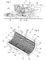
- a crop gathering device 18 is detachably connected in the form of a cutter to harvest harvested crops in the form of crops or other threshable culottes from the field and feed them up and down by a feeder 20 to a multi-drum threshing unit.
- a threshing cylinder 22 arranged one behind the other - a threshing cylinder 22, a stripping drum 24, a superseding working conveyor drum 26, a Tangentialseparator 28 and a turning drum 30 includes.
- Downstream of the turning drum 30 is a straw shaker 32.
- the threshing drum 22 is surrounded by a concave 34 in its lower and rear area.
- the chaff may be ejected at the rear of the screen by a rotating chaff spreader, or it may be discharged through a straw chopper (not shown) disposed downstream of the straw walker 32.
- the cleaned grain from the grain tank 50 may be unloaded by a discharge system with cross augers 54 and a discharge conveyor 56.
- the systems mentioned are driven by means of an internal combustion engine 58 and controlled and controlled by an operator from a driver's cab 60.
- the various devices for threshing, conveying, cleaning and separating are located within the frame 12. Outside the frame 12 is an outer shell, which is largely hinged. It should be noted that the multi-drum thresher shown here is only one embodiment. It could also be replaced by a single transverse threshing cylinder and a downstream separator with a straw walker or one or more separation rotors.
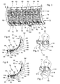
- the second threshing section 78 Downstream of the first threshing section 72 is the second threshing section 78 fixedly connected to the cheeks 62 and constructed by threshing bars 68 extending between the cheeks 62 and basket wires 80 guided by the threshing bars 68.
- the distances between the adjacent threshing bars 68 and adjacent basket wires 80 in the second threshing section 78 are smaller than the distances between the adjacent threshing bars 68 and adjacent basket wires 76 in the first threshing section 72, but could be larger.
- the threshing section 34 Downstream of the second threshing section 78, the threshing section 34 is followed by the third threshing section 82, which is composed of two finger strips 84 arranged one behind the other.
- the finger strips are attached to rectangular bars 86 which extend between the cheeks 62 and by a suitable adjusting drive 88 (see. FIG. 3 ) are rotatable synchronously about their longitudinal axes. This is also on the revelation of DE 10 2009 047 287 A1 directed.
- an axially extending between the cheeks 62 Drum 68 is rigidly attached.
- the aforementioned holding elements 90 serve to releasably fix the inserts 74 in the concave 34. These are between a holding position, as in the FIGS. 4 and 5 is shown, and a release position, as in the FIGS. 6 and 7 is reproduced, movable. Each of the three inserts 74 is associated with a single holding element 90, wherein it would also be possible to use a different number of inserts 74 and / or assign each two or more holding elements 90.
- the holding elements 90 are rigidly attached to a shaft 94.
- the shaft 94 extends axially between the cheeks 62 and through holes in the sections 92 of the curved strips 64. The fixation of the shaft 94 in the axial direction is effected by the cheeks 62 which abut from the outside at the ends of the shaft 94.
- the shaft 94 is rotatable about its longitudinal axis by a drive 96.
- the drive 96 comprises a screw spindle 98, the head 100 of which rests on the front side of the inlet plate 66 on a concave plate holder 100 and whose thread cooperates with a nut 102, which in turn is attached to an angle lever 104.
- the angle lever 104 is connected via a pivot pin 106 with a lower arm 108 of the middle support member 90 which is rigidly attached to the shaft 94.
- a rotation of the screw spindle 98 thus has a displacement of the nut 102 along the screw spindle 98, a displacement of the angle lever 104 and finally a pivoting of the middle support member 90 and the shaft 94 about its longitudinal axis and rotation of the other (rigidly connected to the shaft 94) Retaining elements 90 result.
- the attachment of the screw spindle 98 at the front of the inlet plate 66 allows good accessibility to the drive 96.
- a second, in the FIG. 3 shown screw with a head 110 can serve (via a mechanism, not shown) for adjusting the finger strips 84. It would be conceivable to replace or supplement the manually operated adjustment drive 96 represented here by a power-operated actuator (hydraulic cylinder or electric motor).
- the holding elements 90 comprise in their upper, the shaft 94 adjacent region a tapered hook 112, which extends in the holding position in a matching opening 114 in the frontmost razor 68 of the insert 74 and fixed the insert 74 in the radial direction of the concave 34 , In the release position, however, the hook 112 does not extend into the opening 114.
- the support members 90 further include an eccentric 116 whose outer surface 118 is positioned below the foremost razor 68 of the insert 74.
- the concave 34 is expediently brought into a position as far as possible from the threshing drum 22 by actuators (not shown) serving to adjust the threshing slit.
- the inserts 74 can then be exchanged and by operating the adjusting drive 96, the holding elements 90 are returned to the holding position to lock the inserts 74.
- the inserts 74 are locked downwards (radially) by their curved strips 64, which bear against the sections 92 of the curved strips 64 of the supporting structure of the concave 34.
- the locking is effected by the rearmost threshing 68 of the inserts, which bear against the foremost threshing 68 of the second threshing section 78.
- a locking of the rear portions of the inserts 74 against a radially inwardly directed movement is not provided and also not required, because the crop pushes the inserts 74 in operation to the outside.
- the hooks 112 of the retaining elements 90 do not necessarily have to cooperate with openings introduced into the threshing bars 68 of the inserts 74, but tabs (not shown) may also be attached to the threshing bars 68 into which the hooks 112 penetrate can.
- the shaft 94 may not necessarily be supported on the cheeks 62 and arched ledges 64 of the concave 34, but separate brackets could be provided which would be secured at any location on the concave 34.
Landscapes
- Life Sciences & Earth Sciences (AREA)
- Environmental Sciences (AREA)
- Threshing Machine Elements (AREA)
Applications Claiming Priority (1)
| Application Number | Priority Date | Filing Date | Title |
|---|---|---|---|
| DE201010061863 DE102010061863A1 (de) | 2010-11-24 | 2010-11-24 | Dreschkorb mit wenigstens einem demontierbaren Einsatz |
Publications (2)
| Publication Number | Publication Date |
|---|---|
| EP2457434A1 true EP2457434A1 (fr) | 2012-05-30 |
| EP2457434B1 EP2457434B1 (fr) | 2013-06-26 |
Family
ID=44799783
Family Applications (1)
| Application Number | Title | Priority Date | Filing Date |
|---|---|---|---|
| EP20110184972 Active EP2457434B1 (fr) | 2010-11-24 | 2011-10-13 | Panier de battage doté d'au moins un insert démontable |
Country Status (2)
| Country | Link |
|---|---|
| EP (1) | EP2457434B1 (fr) |
| DE (1) | DE102010061863A1 (fr) |
Cited By (4)
| Publication number | Priority date | Publication date | Assignee | Title |
|---|---|---|---|---|
| CN105009830A (zh) * | 2015-07-29 | 2015-11-04 | 江苏大学 | 一种切纵流滚筒对接负压气流喂入装置 |
| EP3075226A1 (fr) * | 2015-04-02 | 2016-10-05 | Deere & Company | Panier de battage ou de separation dote d'au moins un insert demontable |
| EP3854200A1 (fr) | 2020-01-27 | 2021-07-28 | Deere & Company | Système de battage ou séparation avec insert démontable |
| EP4378299A1 (fr) * | 2022-11-11 | 2024-06-05 | AGCO International GmbH | Système de séparation de grains pour moissonneuse-batteuse |
Families Citing this family (6)
| Publication number | Priority date | Publication date | Assignee | Title |
|---|---|---|---|---|
| CN105103813A (zh) * | 2015-08-13 | 2015-12-02 | 张铁刚 | 脱粒机用脱粒滚筒凹板总成带驱动旋转机构 |
| CN105165290A (zh) * | 2015-08-13 | 2015-12-23 | 张铁刚 | 脱粒机用脱粒滚筒凹板总成链驱动旋转机构 |
| DE202017102477U1 (de) | 2017-04-26 | 2017-05-29 | Ab. Agri-Broker E.K. | Dreschkorb für Mähdrescher |
| DE102017108967B4 (de) | 2017-04-26 | 2022-11-10 | Ab. Agri-Broker E.K. | Dreschkorb für Mähdrescher |
| DE102021128494A1 (de) * | 2021-11-02 | 2023-05-04 | Deere & Company | Dreschkorb für einen Mähdrescher |
| DE102022109160A1 (de) * | 2022-04-13 | 2023-10-19 | Deere & Company | Verschlussklappe für einen Dresch- oder Trennkorb einer Dresch- und/oder Trenneinrichtung |
Citations (6)
| Publication number | Priority date | Publication date | Assignee | Title |
|---|---|---|---|---|
| DE6916279U (de) * | 1969-04-23 | 1969-09-04 | Claas Maschf Gmbh Geb | Verstellbarer dreschkorb |
| US3568682A (en) * | 1969-09-17 | 1971-03-09 | Int Harvester Co | Grate for axial flow combine |
| EP0927512A1 (fr) * | 1998-01-03 | 1999-07-07 | Deere & Company | Segment d'un contre-batteur, contre-batteur et moissonneuse-batteuse |
| EP1059023A2 (fr) | 1999-06-10 | 2000-12-13 | CLAAS Selbstfahrende Erntemaschinen GmbH | Moissonneuse-batteuse |
| EP1197136A1 (fr) | 2000-09-15 | 2002-04-17 | Case Harvesting Systems GmbH | Contrebatteur pour moissonneuse-batteuse |
| DE102009047287A1 (de) | 2009-11-30 | 2011-06-01 | Deere & Company, Moline | Dreschkorb für ein Tangentialdreschwerk |
-
2010
- 2010-11-24 DE DE201010061863 patent/DE102010061863A1/de not_active Withdrawn
-
2011
- 2011-10-13 EP EP20110184972 patent/EP2457434B1/fr active Active
Patent Citations (6)
| Publication number | Priority date | Publication date | Assignee | Title |
|---|---|---|---|---|
| DE6916279U (de) * | 1969-04-23 | 1969-09-04 | Claas Maschf Gmbh Geb | Verstellbarer dreschkorb |
| US3568682A (en) * | 1969-09-17 | 1971-03-09 | Int Harvester Co | Grate for axial flow combine |
| EP0927512A1 (fr) * | 1998-01-03 | 1999-07-07 | Deere & Company | Segment d'un contre-batteur, contre-batteur et moissonneuse-batteuse |
| EP1059023A2 (fr) | 1999-06-10 | 2000-12-13 | CLAAS Selbstfahrende Erntemaschinen GmbH | Moissonneuse-batteuse |
| EP1197136A1 (fr) | 2000-09-15 | 2002-04-17 | Case Harvesting Systems GmbH | Contrebatteur pour moissonneuse-batteuse |
| DE102009047287A1 (de) | 2009-11-30 | 2011-06-01 | Deere & Company, Moline | Dreschkorb für ein Tangentialdreschwerk |
Cited By (5)
| Publication number | Priority date | Publication date | Assignee | Title |
|---|---|---|---|---|
| EP3075226A1 (fr) * | 2015-04-02 | 2016-10-05 | Deere & Company | Panier de battage ou de separation dote d'au moins un insert demontable |
| CN105009830A (zh) * | 2015-07-29 | 2015-11-04 | 江苏大学 | 一种切纵流滚筒对接负压气流喂入装置 |
| EP3854200A1 (fr) | 2020-01-27 | 2021-07-28 | Deere & Company | Système de battage ou séparation avec insert démontable |
| DE102020200948A1 (de) | 2020-01-27 | 2021-07-29 | Deere & Company | Dresch- oder Separieranordnung mit einem demontierbaren Einsatz |
| EP4378299A1 (fr) * | 2022-11-11 | 2024-06-05 | AGCO International GmbH | Système de séparation de grains pour moissonneuse-batteuse |
Also Published As
| Publication number | Publication date |
|---|---|
| EP2457434B1 (fr) | 2013-06-26 |
| DE102010061863A1 (de) | 2012-05-24 |
Similar Documents
| Publication | Publication Date | Title |
|---|---|---|
| EP2457434B1 (fr) | Panier de battage doté d'au moins un insert démontable | |
| DE102009047287B4 (de) | Dreschkorb für ein Tangentialdreschwerk | |
| DE102012210649B4 (de) | Tangentialdreschwerk mit einer Fördertrommel und einer Dresch- oder Abscheidetrommel | |
| EP3420803B1 (fr) | Element de séparation ou de battage pour les récoltes céréalières | |
| DE102015205622B4 (de) | Schrägfördererzusammenbau für einen Mähdrescher | |
| EP1474964A1 (fr) | Méthode et dispositif d'ajustement des ouvertures d'une surface de séparation, en particulier d'un contre-batteur d'une machine de récolte | |
| EP2591664A1 (fr) | Crible pour une installation de nettoyage d'une moissonneuse-batteuse | |
| EP3075226B1 (fr) | Panier de battage ou de séparation dôté d'au moins un insert démontable | |
| EP2014149B1 (fr) | Tambour rotatif de séparation pour une batteuse à plusieurs cylindres | |
| EP3354126B1 (fr) | Couteau et tambour de hachoir pour une ramasseuse-hacheuse | |
| DE102005021766A1 (de) | Schneidwerk mit Fördergurtzusammenbauten | |
| EP2036425B2 (fr) | Agencement de panier de battage pour une moissonneuse-batteuse | |
| EP4209123B1 (fr) | Contre-batteur pour moissonneuse-batteuse | |
| BE1021663B1 (de) | Mehrtrommeldreschwerk | |
| DE2835774A1 (de) | Dreschspalteinstellung fuer maehdrescher der axialflussbauart | |
| DE19709398A1 (de) | Gutbearbeitungsvorrichtung | |
| BE1022970B1 (de) | Verstellanordnung zur Verstellung des Arbeitsspaltes eines Korbes einer Dresch- und/oder Trenneinrichtung | |
| BE1021334B1 (de) | Mähdrescher mit einer zwischen der drescheinrichtung und der reinigung angeordneten nachdrescheinrichtung | |
| DE102018219864B3 (de) | Mähdrescher mit einem Schneckenfördererzusammenbau | |
| DE102016202324B4 (de) | Längenverstellbarer Schneckenfördererzusammenbau für einen Mähdrescher | |
| EP1530895B1 (fr) | Moissoneuse batteuse à recueil de cailloux | |
| EP3854200B1 (fr) | Système de battage ou séparation avec insert démontable | |
| EP2764766A1 (fr) | Mécanisme de battage doté d'un tire-paille et d'un rouleau racleur | |
| EP3081069A1 (fr) | Dispositif mecanique destine a eviter la formation de voute lors du dechargement de recolte a partir d'une tremie d'une moissonneuse-batteuse | |
| EP3335545A1 (fr) | Châssis modulaire pour tambour |
Legal Events
| Date | Code | Title | Description |
|---|---|---|---|
| PUAI | Public reference made under article 153(3) epc to a published international application that has entered the european phase |
Free format text: ORIGINAL CODE: 0009012 |
|
| AK | Designated contracting states |
Kind code of ref document: A1 Designated state(s): AL AT BE BG CH CY CZ DE DK EE ES FI FR GB GR HR HU IE IS IT LI LT LU LV MC MK MT NL NO PL PT RO RS SE SI SK SM TR |
|
| AX | Request for extension of the european patent |
Extension state: BA ME |
|
| 17P | Request for examination filed |
Effective date: 20121130 |
|
| GRAP | Despatch of communication of intention to grant a patent |
Free format text: ORIGINAL CODE: EPIDOSNIGR1 |
|
| GRAS | Grant fee paid |
Free format text: ORIGINAL CODE: EPIDOSNIGR3 |
|
| GRAA | (expected) grant |
Free format text: ORIGINAL CODE: 0009210 |
|
| AK | Designated contracting states |
Kind code of ref document: B1 Designated state(s): AL AT BE BG CH CY CZ DE DK EE ES FI FR GB GR HR HU IE IS IT LI LT LU LV MC MK MT NL NO PL PT RO RS SE SI SK SM TR |
|
| REG | Reference to a national code |
Ref country code: GB Ref legal event code: FG4D Free format text: NOT ENGLISH |
|
| REG | Reference to a national code |
Ref country code: CH Ref legal event code: EP |
|
| REG | Reference to a national code |
Ref country code: AT Ref legal event code: REF Ref document number: 618268 Country of ref document: AT Kind code of ref document: T Effective date: 20130715 |
|
| REG | Reference to a national code |
Ref country code: IE Ref legal event code: FG4D Free format text: LANGUAGE OF EP DOCUMENT: GERMAN |
|
| REG | Reference to a national code |
Ref country code: DE Ref legal event code: R096 Ref document number: 502011000952 Country of ref document: DE Effective date: 20130822 |
|
| PG25 | Lapsed in a contracting state [announced via postgrant information from national office to epo] |
Ref country code: NO Free format text: LAPSE BECAUSE OF FAILURE TO SUBMIT A TRANSLATION OF THE DESCRIPTION OR TO PAY THE FEE WITHIN THE PRESCRIBED TIME-LIMIT Effective date: 20130926 Ref country code: LT Free format text: LAPSE BECAUSE OF FAILURE TO SUBMIT A TRANSLATION OF THE DESCRIPTION OR TO PAY THE FEE WITHIN THE PRESCRIBED TIME-LIMIT Effective date: 20130626 Ref country code: FI Free format text: LAPSE BECAUSE OF FAILURE TO SUBMIT A TRANSLATION OF THE DESCRIPTION OR TO PAY THE FEE WITHIN THE PRESCRIBED TIME-LIMIT Effective date: 20130626 Ref country code: SI Free format text: LAPSE BECAUSE OF FAILURE TO SUBMIT A TRANSLATION OF THE DESCRIPTION OR TO PAY THE FEE WITHIN THE PRESCRIBED TIME-LIMIT Effective date: 20130626 Ref country code: GR Free format text: LAPSE BECAUSE OF FAILURE TO SUBMIT A TRANSLATION OF THE DESCRIPTION OR TO PAY THE FEE WITHIN THE PRESCRIBED TIME-LIMIT Effective date: 20130927 Ref country code: SE Free format text: LAPSE BECAUSE OF FAILURE TO SUBMIT A TRANSLATION OF THE DESCRIPTION OR TO PAY THE FEE WITHIN THE PRESCRIBED TIME-LIMIT Effective date: 20130626 |
|
| REG | Reference to a national code |
Ref country code: LT Ref legal event code: MG4D |
|
| PG25 | Lapsed in a contracting state [announced via postgrant information from national office to epo] |
Ref country code: BG Free format text: LAPSE BECAUSE OF FAILURE TO SUBMIT A TRANSLATION OF THE DESCRIPTION OR TO PAY THE FEE WITHIN THE PRESCRIBED TIME-LIMIT Effective date: 20130926 Ref country code: RS Free format text: LAPSE BECAUSE OF FAILURE TO SUBMIT A TRANSLATION OF THE DESCRIPTION OR TO PAY THE FEE WITHIN THE PRESCRIBED TIME-LIMIT Effective date: 20130626 Ref country code: HR Free format text: LAPSE BECAUSE OF FAILURE TO SUBMIT A TRANSLATION OF THE DESCRIPTION OR TO PAY THE FEE WITHIN THE PRESCRIBED TIME-LIMIT Effective date: 20130626 |
|
| REG | Reference to a national code |
Ref country code: NL Ref legal event code: VDEP Effective date: 20130626 |
|
| PG25 | Lapsed in a contracting state [announced via postgrant information from national office to epo] |
Ref country code: LV Free format text: LAPSE BECAUSE OF FAILURE TO SUBMIT A TRANSLATION OF THE DESCRIPTION OR TO PAY THE FEE WITHIN THE PRESCRIBED TIME-LIMIT Effective date: 20130626 |
|
| PG25 | Lapsed in a contracting state [announced via postgrant information from national office to epo] |
Ref country code: EE Free format text: LAPSE BECAUSE OF FAILURE TO SUBMIT A TRANSLATION OF THE DESCRIPTION OR TO PAY THE FEE WITHIN THE PRESCRIBED TIME-LIMIT Effective date: 20130626 Ref country code: CY Free format text: LAPSE BECAUSE OF FAILURE TO SUBMIT A TRANSLATION OF THE DESCRIPTION OR TO PAY THE FEE WITHIN THE PRESCRIBED TIME-LIMIT Effective date: 20130828 Ref country code: PT Free format text: LAPSE BECAUSE OF FAILURE TO SUBMIT A TRANSLATION OF THE DESCRIPTION OR TO PAY THE FEE WITHIN THE PRESCRIBED TIME-LIMIT Effective date: 20131028 Ref country code: SK Free format text: LAPSE BECAUSE OF FAILURE TO SUBMIT A TRANSLATION OF THE DESCRIPTION OR TO PAY THE FEE WITHIN THE PRESCRIBED TIME-LIMIT Effective date: 20130626 Ref country code: CZ Free format text: LAPSE BECAUSE OF FAILURE TO SUBMIT A TRANSLATION OF THE DESCRIPTION OR TO PAY THE FEE WITHIN THE PRESCRIBED TIME-LIMIT Effective date: 20130626 Ref country code: IS Free format text: LAPSE BECAUSE OF FAILURE TO SUBMIT A TRANSLATION OF THE DESCRIPTION OR TO PAY THE FEE WITHIN THE PRESCRIBED TIME-LIMIT Effective date: 20131026 |
|
| PG25 | Lapsed in a contracting state [announced via postgrant information from national office to epo] |
Ref country code: RO Free format text: LAPSE BECAUSE OF FAILURE TO SUBMIT A TRANSLATION OF THE DESCRIPTION OR TO PAY THE FEE WITHIN THE PRESCRIBED TIME-LIMIT Effective date: 20130626 Ref country code: PL Free format text: LAPSE BECAUSE OF FAILURE TO SUBMIT A TRANSLATION OF THE DESCRIPTION OR TO PAY THE FEE WITHIN THE PRESCRIBED TIME-LIMIT Effective date: 20130626 Ref country code: NL Free format text: LAPSE BECAUSE OF FAILURE TO SUBMIT A TRANSLATION OF THE DESCRIPTION OR TO PAY THE FEE WITHIN THE PRESCRIBED TIME-LIMIT Effective date: 20130626 Ref country code: ES Free format text: LAPSE BECAUSE OF FAILURE TO SUBMIT A TRANSLATION OF THE DESCRIPTION OR TO PAY THE FEE WITHIN THE PRESCRIBED TIME-LIMIT Effective date: 20131007 |
|
| PG25 | Lapsed in a contracting state [announced via postgrant information from national office to epo] |
Ref country code: CY Free format text: LAPSE BECAUSE OF FAILURE TO SUBMIT A TRANSLATION OF THE DESCRIPTION OR TO PAY THE FEE WITHIN THE PRESCRIBED TIME-LIMIT Effective date: 20130626 |
|
| PG25 | Lapsed in a contracting state [announced via postgrant information from national office to epo] |
Ref country code: DK Free format text: LAPSE BECAUSE OF FAILURE TO SUBMIT A TRANSLATION OF THE DESCRIPTION OR TO PAY THE FEE WITHIN THE PRESCRIBED TIME-LIMIT Effective date: 20130626 |
|
| PLBE | No opposition filed within time limit |
Free format text: ORIGINAL CODE: 0009261 |
|
| STAA | Information on the status of an ep patent application or granted ep patent |
Free format text: STATUS: NO OPPOSITION FILED WITHIN TIME LIMIT |
|
| PG25 | Lapsed in a contracting state [announced via postgrant information from national office to epo] |
Ref country code: MC Free format text: LAPSE BECAUSE OF FAILURE TO SUBMIT A TRANSLATION OF THE DESCRIPTION OR TO PAY THE FEE WITHIN THE PRESCRIBED TIME-LIMIT Effective date: 20130626 |
|
| 26N | No opposition filed |
Effective date: 20140327 |
|
| REG | Reference to a national code |
Ref country code: DE Ref legal event code: R097 Ref document number: 502011000952 Country of ref document: DE Effective date: 20140327 |
|
| REG | Reference to a national code |
Ref country code: IE Ref legal event code: MM4A |
|
| REG | Reference to a national code |
Ref country code: FR Ref legal event code: ST Effective date: 20140630 |
|
| PG25 | Lapsed in a contracting state [announced via postgrant information from national office to epo] |
Ref country code: FR Free format text: LAPSE BECAUSE OF NON-PAYMENT OF DUE FEES Effective date: 20131031 |
|
| PG25 | Lapsed in a contracting state [announced via postgrant information from national office to epo] |
Ref country code: IE Free format text: LAPSE BECAUSE OF NON-PAYMENT OF DUE FEES Effective date: 20131013 |
|
| PG25 | Lapsed in a contracting state [announced via postgrant information from national office to epo] |
Ref country code: SM Free format text: LAPSE BECAUSE OF FAILURE TO SUBMIT A TRANSLATION OF THE DESCRIPTION OR TO PAY THE FEE WITHIN THE PRESCRIBED TIME-LIMIT Effective date: 20130626 |
|
| REG | Reference to a national code |
Ref country code: CH Ref legal event code: PL |
|
| PG25 | Lapsed in a contracting state [announced via postgrant information from national office to epo] |
Ref country code: TR Free format text: LAPSE BECAUSE OF FAILURE TO SUBMIT A TRANSLATION OF THE DESCRIPTION OR TO PAY THE FEE WITHIN THE PRESCRIBED TIME-LIMIT Effective date: 20130626 |
|
| PG25 | Lapsed in a contracting state [announced via postgrant information from national office to epo] |
Ref country code: LU Free format text: LAPSE BECAUSE OF NON-PAYMENT OF DUE FEES Effective date: 20131013 Ref country code: LI Free format text: LAPSE BECAUSE OF NON-PAYMENT OF DUE FEES Effective date: 20141031 Ref country code: CH Free format text: LAPSE BECAUSE OF NON-PAYMENT OF DUE FEES Effective date: 20141031 Ref country code: MK Free format text: LAPSE BECAUSE OF FAILURE TO SUBMIT A TRANSLATION OF THE DESCRIPTION OR TO PAY THE FEE WITHIN THE PRESCRIBED TIME-LIMIT Effective date: 20130626 Ref country code: HU Free format text: LAPSE BECAUSE OF FAILURE TO SUBMIT A TRANSLATION OF THE DESCRIPTION OR TO PAY THE FEE WITHIN THE PRESCRIBED TIME-LIMIT; INVALID AB INITIO Effective date: 20111013 |
|
| PG25 | Lapsed in a contracting state [announced via postgrant information from national office to epo] |
Ref country code: MT Free format text: LAPSE BECAUSE OF FAILURE TO SUBMIT A TRANSLATION OF THE DESCRIPTION OR TO PAY THE FEE WITHIN THE PRESCRIBED TIME-LIMIT Effective date: 20130626 |
|
| GBPC | Gb: european patent ceased through non-payment of renewal fee |
Effective date: 20151013 |
|
| PG25 | Lapsed in a contracting state [announced via postgrant information from national office to epo] |
Ref country code: GB Free format text: LAPSE BECAUSE OF NON-PAYMENT OF DUE FEES Effective date: 20151013 |
|
| REG | Reference to a national code |
Ref country code: AT Ref legal event code: MM01 Ref document number: 618268 Country of ref document: AT Kind code of ref document: T Effective date: 20161013 |
|
| PG25 | Lapsed in a contracting state [announced via postgrant information from national office to epo] |
Ref country code: AT Free format text: LAPSE BECAUSE OF NON-PAYMENT OF DUE FEES Effective date: 20161013 |
|
| PG25 | Lapsed in a contracting state [announced via postgrant information from national office to epo] |
Ref country code: AL Free format text: LAPSE BECAUSE OF FAILURE TO SUBMIT A TRANSLATION OF THE DESCRIPTION OR TO PAY THE FEE WITHIN THE PRESCRIBED TIME-LIMIT Effective date: 20130626 |
|
| PGFP | Annual fee paid to national office [announced via postgrant information from national office to epo] |
Ref country code: IT Payment date: 20221020 Year of fee payment: 12 |
|
| PG25 | Lapsed in a contracting state [announced via postgrant information from national office to epo] |
Ref country code: IT Free format text: LAPSE BECAUSE OF NON-PAYMENT OF DUE FEES Effective date: 20231013 |
|
| PG25 | Lapsed in a contracting state [announced via postgrant information from national office to epo] |
Ref country code: IT Free format text: LAPSE BECAUSE OF NON-PAYMENT OF DUE FEES Effective date: 20231013 |
|
| PGFP | Annual fee paid to national office [announced via postgrant information from national office to epo] |
Ref country code: DE Payment date: 20240919 Year of fee payment: 14 |
|
| PGFP | Annual fee paid to national office [announced via postgrant information from national office to epo] |
Ref country code: BE Payment date: 20241028 Year of fee payment: 14 |