EP2457663A1 - Getriebemotor für ein Mühlenantriebssystem - Google Patents
Getriebemotor für ein Mühlenantriebssystem Download PDFInfo
- Publication number
- EP2457663A1 EP2457663A1 EP10015077A EP10015077A EP2457663A1 EP 2457663 A1 EP2457663 A1 EP 2457663A1 EP 10015077 A EP10015077 A EP 10015077A EP 10015077 A EP10015077 A EP 10015077A EP 2457663 A1 EP2457663 A1 EP 2457663A1
- Authority
- EP
- European Patent Office
- Prior art keywords
- rotor
- gear
- lubricant
- stator
- transmission
- Prior art date
- Legal status (The legal status is an assumption and is not a legal conclusion. Google has not performed a legal analysis and makes no representation as to the accuracy of the status listed.)
- Granted
Links
Images
Classifications
-
- B—PERFORMING OPERATIONS; TRANSPORTING
- B02—CRUSHING, PULVERISING, OR DISINTEGRATING; PREPARATORY TREATMENT OF GRAIN FOR MILLING
- B02C—CRUSHING, PULVERISING, OR DISINTEGRATING IN GENERAL; MILLING GRAIN
- B02C15/00—Disintegrating by milling members in the form of rollers or balls co-operating with rings or discs
- B02C15/006—Ring or disc drive gear arrangement
Definitions
- Known mill drive systems include one or more gear stages for driving power conversion of an electric motor.
- Gear stages and electric motor are closely linked to a processing process within e.g. a power plant coupled to a bowl mill, a mixing drum, a crusher, a tube mill or a rotary kiln, which is subject to considerable repercussions of the processing process.
- bevel gear stages are used to connect the electric motor to the drive train.
- WO 2008/031694 A1 discloses a mill drive system having a gear unit locatable below a grinding table.
- the transmission comprises at least one planetary stage and has a vertical shaft position.
- an electric motor is integrated, which is connected to a lubricant supply circuit of the transmission, whose rotor and stator have vertically extending axes and whose cooling is carried out by means of circulating through the gear lubricant.
- WO 2009/068484 A1 is a spur gear with one or more gear stages for driving a gear wheel enclosed by a work machine described which includes a transmission gear housing receiving the gear and arranged on an output shaft of an output stage, adjustable movable pinion meshing with the ring gear.
- the gear housing consists of a first inherently rigid housing part and a second rigid housing part.
- the first housing part encloses the output stage with the output shaft and the adjustable pinion gear and has the transmission on outstanding side walls, which rest on the foundation.
- the second housing part is fastened to the first housing part without contact with the foundation on one end face.
- WO 2010/20287 is a mill drive system with an integrated motor-gear unit is known which has a common cooling circuit.
- the motor-gear unit is supported on a bottom plate of a housing comprising the motor-gear unit.
- a mill drive system is described with a can be arranged below a grinding table gear with at least one planetary and / or spur and an integrated in a housing of the transmission electric motor.
- the mill drive system comprises a converter with an associated control device for non-interlocking speed control of the motor.
- the present invention is therefore an object of the invention to provide a geared motor for a mill drive system, on the one hand to avoid transmission damage caused by short breaks in the drive train and on the other hand, a reduction of bending forces from a grinding process.
- the geared motor according to the invention comprises a gear which can be arranged below a grinding plate or laterally of a grinding drum and has at least one planetary gear stage which has a vertical or horizontal shaft position.
- an electric motor is integrated in a housing of the transmission, which is connected to a lubricant supply circuit of the transmission.
- Rotor and stator of the motor have axes extending parallel to the shaft position of the gearbox. Cooling of the engine takes place by means of circulating lubricant through the gearbox.
- a lubricating oil-tight casing for rotor or stator windings of the motor to seal against within the housing provided circulating lubricant.
- the mill drive system comprises a converter with an associated control device for the non-interlocking speed control of the motor.
- a ring gear of the at least one planetary gear is radially surrounded by both the rotor and the stator. Rotor and stator are preferably arranged concentrically to the ring gear.
- inverter By using an inverter, a variety of application-specific translation variants can be realized with a reduced number of Veriereungsbaumaschinemaschinetypen.
- speed control By the speed control, the respective processing process Moreover, with the mill drive system according to the invention, they can be operated at an optimum operating point. This improves the efficiency of the milling process. This in turn allows a reduction in energy consumption.
- the engine may be designed, for example, as an external rotor.
- the ring gear forms a stator.
- a sun gear shaft of the at least one planetary gear is connected to a rotor carrier.
- At least one axially extending opening may be provided in the rotor carrier for a lubricant outlet from the transmission into a lubricant collecting area or container.
- the motor can also be designed as an internal rotor.
- the ring gear is preferably rotatably connected to the rotor.
- seals are provided only on a driven plate, on lubricant supply lines, on electrical power supply leads and on at least one feed for a measuring device. This allows a further reduction of mechanical components and thus contributes to increased reliability.
- the motor is a permanent-magnet synchronous machine whose rotor magnet system is welded into a stainless steel jacket. Since no thermal losses occur on the rotor in this way, no rotor cooling is required.
- the motor can also be designed as a squirrel cage machine.
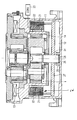
- the mill drive system shown in the figure comprises a arranged below a Mahltellers gear 1 with two planetary stages. Both the drive-side planetary stage and the output-side planetary stage have a vertical shaft position. Both planetary stages each include a ring gear, a planetary carrier with planetary gears mounted therein, and a sun gear. The ring gears of the planetary stages are fixedly connected to a transmission housing 11. The planet carrier of the driven-side planetary stage can be connected to the grinding table and mounted by means of a thrust bearing 13. The sun gear of the drive-side planetary stage is connected to a rotor shaft 28 of an electric motor 2 integrated into the transmission housing 11, which rotor comprises a rotor 21 and a stator 22 surrounding it radially. Rotor 21 and stator 22 have vertically extending axes.
- the ring gear 14 of the input-side planetary gear is radially surrounded by both the rotor 21 and the stator 22. Rotor 21 and stator 22 are arranged concentrically to the ring gear 14 of the input-side planetary gear.
- the motor 2 is designed as an external rotor.
- the ring gear 14 of the drive-side planetary gear here forms a stator.
- the rotor shaft 28 or a sun gear shaft of the drive-side planetary gear stage is connected to a rotor carrier 27, on which the rotor 21 is supported.
- the motor 2 could in principle also be designed as an internal rotor.
- the ring gear 14 of the drive-side planetary gear can be rotatably connected to the rotor 21.
- the rotor shaft 28 is mounted by means of a radial bearing 24 arranged between the engine 2 and the transmission 1, a radial bearing 25 arranged below the motor 2 in a lubricant sump 12, and an axial bearing 26 likewise arranged below the motor 2. In this way, with a relatively short rotor shaft 28, a very good centering of the rotor 21 is possible.
- Rotor shaft 28 and sun gear of the drive-side planetary stage are preferably connected via a coupling arranged below or above the motor 2.
- the planet carrier of the drive-side planetary stage and the sun gear of the output-side planetary stage are interconnected.
- the engine 2 is connected to a lubricant supply circuit of the transmission 1, wherein the lubricant from the lubricant sump 12 is pumped to lubrication points in the gearbox 1 and runs from there via the engine 2 into the lubricant sump 12. In this way, there is a cooling of the engine 2 by means of circulating through the gear 1 lubricant.
- At least one lubricant supply channel is here guided to stator cooling plates, which can be flowed in with lubricant circulating through the transmission 1.
- lubricating oil can be sprayed specifically for cooling the stator 22, which is conveyed through cooling devices of the stator 22.
- a lubricating oil-tight sheath of the rotor 21 is provided for sealing against circulating within the housing lubricant.
- a lubricating oil-tight sheathing of a stator core which includes windings of the stator 22.
- a significant increase in the air gap of the engine 2 is not required, as it undergoes only a small magnification by the oil-tight sheaths.
- the motor 2 is in the present embodiment, a permanent-magnet synchronous machine whose rotor magnet system is welded in a stainless steel sheath. This allows particularly low electrical losses.
- the mill drive system shown in the figure further comprises a converter 23 with an associated control device for non-interlocking speed control of the motor 2, so that there is no play between the tooth flanks of the transmission 1 in the direction of rotation.
- Mechanical natural frequencies of a mill gearbox motor system become uncritical when using the inverter 23 due to system component decoupling. Tooth flanks of the transmission 1 are held by applying a minimum torque under constant adhesion. As a result, direction-changing loads on the tooth flanks are largely prevented.
Landscapes
- Engineering & Computer Science (AREA)
- Food Science & Technology (AREA)
- Connection Of Motors, Electrical Generators, Mechanical Devices, And The Like (AREA)
- Retarders (AREA)
- General Details Of Gearings (AREA)
Abstract
Description
- Bekannte Mühlenantriebssysteme umfassen eine oder mehrere Getriebestufen zur Antriebsleistungswandlung eines Elektromotors. Getriebestufen und Elektromotor bilden dabei einen eng an einen Verarbeitungsprozeß innerhalb z.B. einer Schüsselmühle, einer Mischtrommel, eines Brechers, einer Rohrmühle oder eines Drehrohrofens gekoppelten Antriebsstrang, der erheblichen Rückwirkungen des Verarbeitungsprozesses ausgesetzt ist. Üblicherweise werden Kegelradstufen zur Anbindung des Elektromotors an den Antriebsstrang verwendet.
- In
DE 39 31 116 A1 ist eine Antriebsvorrichtung für eine Mühle in Vertikalbauweise beschrieben, bei der ein Gehäuse eines Vorsatzgetriebes fest mit der Mühle verschraubt ist. Hierbei ist eine exakte Ausrichtung von weit auseinander liegenden Achsen von Antriebsritzel und Zahnkranz erforderlich. Darüber hinaus bewirkt eine Einleitung axialer Mühlenkräfte über ein Axial-Drucklager in ein gemeinsames Getriebegehäuse erhebliche Belastungen für einen Verzahnungseingriff im Vorsatzgetriebe. Durch einen gemeinsamen großen Getriebe- und Mühlenlagerinnenraum wird eine schnelle Verschmutzung von Schmieröl für die Antriebsvorrichtung begünstigt. Außerdem erweist sich eine mechanische Leistungsverzweigung im Vorsatzgetriebe angesichts einer fehlenden Kompensation überzähliger Zwangskräfte als problematisch. - Aus
JP 2005 052799 A -
WO 2008/031694 A1 offenbart ein Mühlenantriebssystem mit einem unterhalb eines Mahltellers anordenbaren Getriebe. Das Getriebe umfaßt zumindest eine Planetenstufe und weist eine vertikale Wellenlage auf. In ein Gehäuse des Getriebes ist ein elektrischer Motor integriert, der an einen Schmierstoffversorgungskreislauf des Getriebes angeschlossen ist, dessen Rotor und Stator sich vertikal erstreckende Achsen aufweisen und dessen Kühlung mittels durch das Getriebe zirkulierenden Schmierstoffs erfolgt. - In
WO 2009/068484 A1 ist ein Stirnradgetriebe mit einer oder mehreren Getriebestufen zum Antrieb einer von einem Zahnkranz umschlossenen Arbeitsmaschine beschrieben, das ein die Getriebestufen aufnehmendes Getriebegehäuse und ein auf einer Abtriebswelle einer Abtriebsstufe angeordnetes, einstellbewegliches Zahnritzel umfaßt, das mit dem Zahnkranz kämmt. Das Getriebegehäuse besteht aus einem ersten in sich steifen Gehäuseteil und aus einem zweiten starren Gehäuseteil. Der erste Gehäuseteil umschließt die Abtriebsstufe mit der Abtriebswelle und dem einstellbeweglichen Zahnritzel und weist das Getriebe überragende Seitenwände auf, die auf dem Fundament aufruhen. Der zweite Gehäuseteil ist ohne Berührung mit dem Fundament an einer Stirnseite an dem ersten Gehäuseteil befestigt. - Aus
WO 2010/20287 - In der älteren europäischen Patentanmeldung mit dem Anmeldeaktenzeichen
09011589.0 - Der vorliegenden Erfindung liegt daher die Aufgabe zugrunde, einen Getriebemotor für ein Mühlenantriebssystem zu schaffen, das einerseits eine Vermeidung von Getriebeschäden durch Kurzunterbrechungen im Antriebsstrang und andererseits eine Reduktion von Biegekräften aus einem Mahlprozeß ermöglicht.
- Erfindungsgemäß wird diese Aufgabe durch einen Getriebemotor für ein Mühlenantriebssystem mit den in Anspruch 1 angegebenen Merkmalen gelöst. Vorteilhafte Weiterbildungen der vorliegenden Erfindung sind in den abhängigen Ansprüchen angegeben.
- Der erfindungsgemäße Getriebemotor umfaßt ein unterhalb eines Mahltellers oder seitlich einer Mahltrommel anordenbares Getriebe mit zumindest einer Planetenradstufe, das eine vertikale oder horizontale Wellenlage aufweist. Außerdem ist in ein Gehäuse des Getriebes ein elektrischer Motor integriert, der an einen Schmierstoffversorgungskreislauf des Getriebes angeschlossen ist. Rotor und Stator des Motors weisen sich parallel zur Wellenlage des Getriebes erstreckende Achsen auf. Eine Kühlung des Motors erfolgt mittels durch das Getriebe zirkulierenden Schmierstoffs. Darüber hinaus ist eine schmieröldichte Ummantelung für Rotor- bzw. Statorwicklungen des Motors zur Abdichtung gegenüber innerhalb des Gehäuses zirkulierendem Schmierstoff vorgesehen. Des weiteren umfaßt das erfindungsgemäße Mühlenantriebssystem einen Umrichter mit einer zugeordneten Regelungseinrichtung zur verzahnungsspielfreien Drehzahlregelung des Motors. Ein Hohlrad der zumindest einen Planetenradstufe ist sowohl vom Rotor als auch vom Stator radial umgeben. Rotor und Stator sind vorzugsweise konzentrisch zum Hohlrad angeordnet. Durch eine Anordnung des Motors um das Hohlrad kann eine verkürzte Baulänge realisiert werden. Hieraus resultiert eine minimierte Biegearmlänge für Hebelkräfte aus einem Mahlprozeß. Aufgrund der Anordnung des Motors um das Hohlrad ist auch ein Entfall einer Kardanverbindung zwischen Motor und Getriebe sowie eines externen Motorfundaments möglich.
- Aufgrund einer Integration des Motors in den Schmierstoffkreislauf des Getriebes kann auf aufwendige Belüftungsmaßnahmen zur ausreichenden Kühlung des Motors verzichtet werden. Durch Verwendung eines Umrichters zur Motordrehzahlregelung wird Entkopplung zwischen Netzversorgung und Motordrehmoment erzielt. Auf diese Weise können Verzahnungsschäden bei Kurzunterbrechungen infolge eines Netzausfalls vermieden werden, da durch einen Netzausfall aufgrund der erfindungsgemäßen Drehzahlregelung des Motors kein Verzahnungsspiel in Drehrichtung im Getriebe hervorgerufen wird. Durch eine komplett vertikale oder horizontale Anordnung von Mahlteller, Getriebe und Motor ist außerdem ein Verzicht auf verhältnismäßig teuere Kegelradgetriebe möglich. Durch den Verzicht auf Kegelradgetriebe und eine Luftkühlung des Motors werden außerdem Geräuschemissionen deutlich reduziert.
- Durch Verwendung eines Umrichters kann eine Vielzahl anwendungsspezifischer Übersetzungsvarianten bei reduzierter Anzahl von Verzahnungsbauteiletypen realisiert werden. Durch die Drehzahlregelung kann der jeweilige Verarbeitungsprozeß mit dem erfindungsgemäßen Mühlenantriebssystem darüber hinaus in einem optimalen Arbeitspunkt betrieben werden. Hierdurch wird die Effizienz des Mahlprozesses verbessert. Dies ermöglicht wiederum eine Energieverbrauchsreduktion.
- Der Motor kann beispielsweise als Außenläufer ausgeführt sein. Dabei bildet das Hohlrad einen Statorträger. Entsprechend einer weiteren Ausgestaltung der vorliegenden Erfindung ist eine Sonnenradwelle der zumindest einen Planetenradstufe mit einem Rotorträger verbunden. In dem Rotorträger kann zumindest eine sich axial erstreckende Öffnung für einen Schmierstoffablauf vom Getriebe in einen Schmierstoffsammelbereich oder -behälter vorgesehen sein. Alternativ zu einer Ausgestaltung als Außenläufer kann der Motor auch als Innenläufer ausgeführt sein. In diesem Fall ist das Hohlrad vorzugsweise drehfest mit dem Rotor verbunden.
- Entsprechend einer bevorzugten Ausgestaltung der vorliegenden Erfindung sind Dichtungen nur noch an einem Abtriebsteller, an Schmierstoffversorgungsleitungen, an elektrischen Energieversorgungszuführungen und an zumindest einer Zuführung für eine Meßeinrichtung vorgesehen. Dies ermöglicht eine weitere Reduktion mechanischer Bauteile und trägt damit zu einer erhöhten Zuverlässigkeit bei.
- Entsprechend einer vorteilhaften Weiterbildung der vorliegenden Erfindung ist der Motor eine permanenterregte Synchronmaschine ist, deren Rotor-Magnetsystem in einen Edelstahlmantel eingeschweißt ist. Da am Rotor auf diese Weise keine thermischen Verluste entstehen, ist keine Rotorkühlung erforderlich. Alternativ zu einer permanenterregten Synchronmaschine kann der Motor auch als Kurzschlußläufermaschine ausgestaltet sein.
- Die vorliegende Erfindung wird nachfolgend an einem Ausführungsbeispiel anhand der Zeichnung näher erläutert. Es zeigt die
- Figur
- ein Mühlenantriebssystem mit einem erfindungsgemäβen Getriebemotor in einer Schnittdarstellung.
- Das in der Figur dargestellte Mühlenantriebssystem umfaßt ein unterhalb eines Mahltellers angeordnetes Getriebe 1 mit zwei Planetenstufen. Sowohl antriebsseitigen Planetenstufe als auch abtriebsseitige Planetenstufe weisen eine vertikale Wellenlage auf. Beide Planetenstufen umfassen jeweils ein Hohlrad, einen Planetenträger mit darin gelagerten Planetenrädern und ein Sonnenrad. Die Hohlräder der Planetenstufen sind fest mit einem Getriebegehäuse 11 verbunden. Der Planetenträger der abtriebsseitigen Planetenstufe ist mit dem Mahlteller verbindbar und mittels eines Axiallagers 13 gelagert. Das Sonnenrad der antriebsseitigen Planetenstufe ist mit einer Rotorwelle 28 eines in das Getriebegehäuse 11 integrierten elektrischen Motors 2 verbunden, der einen Rotor 21 und einen diesen radial umgebenden Stator 22 umfaßt. Rotor 21 und Stator 22 weisen sich vertikal erstreckende Achsen auf.
- Das Hohlrad 14 der antriebsseitigen Planetenradstufe ist sowohl vom Rotor 21 als auch vom Stator 22 radial umgeben. Dabei sind Rotor 21 und Stator 22 sind konzentrisch zum Hohlrad 14 der antriebsseitigen Planetenradstufe angeordnet. Im vorliegenden Ausführungsbeispiel ist der Motor 2 ist als Außenläufer ausgeführt. Das Hohlrad 14 der antriebsseitigen Planetenradstufe bildet hierbei einen Statorträger. Die Rotorwelle 28 bzw. eine Sonnenradwelle der antriebsseitigen Planetenradstufe ist mit einem Rotorträger 27 verbunden, auf dem der Rotor 21 abgestützt ist.
- Alternativ zu einer in der Figur dargestellten Ausgestaltung als Außenläufer könnte der Motor 2 grundsätzlich auch als Innenläufer ausgeführt sein. In diesem Fall kann das Hohlrad 14 der antriebsseitigen Planetenradstufe drehfest mit dem Rotor 21 verbunden werden.
- Die Rotorwelle 28 ist mittels eines zwischen Motor 2 und Getriebe 1 angeordneten Radiallagers 24, eines unterhalb der Motors 2 in einem Schmierstoffsumpf 12 angeordneten Radiallagers 25 sowie eines ebenfalls unterhalb der Motors 2 angeordneten Axiallagers 26 gelagert. Auf diese Weise ist bei einer relativ kurzen Rotorwelle 28 eine sehr gute Zentrierung des Rotors 21 möglich. Rotorwelle 28 und Sonnenrad der antriebsseitigen Planetenstufe sind vorzugsweise über eine unterhalb oder oberhalb des Motors 2 angeordnete Kupplung verbunden. Darüber hinaus sind im vorliegenden Ausführungsbeispiel der Planetenträger der antriebsseitigen Planetenstufe und das Sonnenrad der abtriebsseitigen Planetenstufe miteinander verbunden.
- Der Motor 2 ist an einen Schmierstoffversorgungskreislauf des Getriebes 1 angeschlossen, bei dem Schmierstoff aus dem Schmierstoffsumpf 12 zu Schmierungsstellen im Getriebe 1 gepumpt wird und von dort über den Motor 2 in den Schmierstoffsumpf 12 abläuft. Auf diese Weise erfolgt eine Kühlung des Motors 2 mittels durch das Getriebe 1 zirkulierenden Schmierstoffs. Zumindest ein in der Figur nicht explizit dargestellter Schmierstoffversorgungskanal ist hierbei zu Statorkühlblechen geführt, das mit durch das Getriebe 1 zirkulierendem Schmierstoff anströmbar ist. Zusätzlich kann gezielt Schmieröl zur Kühlung des Stators 22 angesprüht werden, das durch Kühleinrichtungen des Stators 22 gefördert wird.
- Am Rotorträger 27 ist eine schmieröldichte Ummantelung des Rotors 21 zur Abdichtung gegenüber innerhalb des Gehäuses zirkulierendem Schmierstoff vorgesehen. In entsprechender Weise schließt sich an einen Luftspalt zwischen Rotor 21 und Stator 22 in radialer Richtung eine schmieröldichte Ummantelung eines Ständerblechpakets an, das Wicklungen des Stators 22 umfaßt. Eine deutliche Vergrößerung des Luftspalts des Motors 2 ist nicht erforderlich, da dieser durch die schmieröldichten Ummantelungen lediglich eine geringe Vergrößerung erfährt. Der Motor 2 ist im vorliegenden Ausführungsbeispiel eine permanenterregte Synchronmaschine, deren Rotor-Magnetsystem in einen Edelstahlmantel eingeschweißt ist. Dies ermöglicht besonders geringe elektrische Verluste.
- Das in der Figur dargestellte Mühlenantriebssystem weist ferner einen Umrichter 23 mit einer zugeordneten Regelungseinrichtung zur verzahnungsspielfreien Drehzahlregelung des Motors 2 auf, so daß zwischen Zahnflanken des Getriebes 1 in Drehrichtung kein Spiel besteht. Mechanischen Eigenfrequenzen eines Mühle-Getriebe-Motor-Systems werden bei Verwendung des Umrichters 23 unkritisch infolge einer Systemkomponenten-Entkoppelung. Zahnflanken des Getriebes 1 werden dabei durch Aufschaltung eines Mindestdrehmoments unter ständigem Kraftschluß gehalten. Hierdurch werden richtungsändernde Belastungen der Zahnflanken weitgehend unterbunden.
- Die Anwendung der vorliegenden Erfindung ist nicht auf das beschriebene Ausführungsbeispiel beschränkt.
Claims (10)
- Getriebemotor für ein Mühlenantriebssystem mit- einem unterhalb eines Mahltellers oder seitlich einer Mahltrommel anordenbaren Getriebe mit zumindest einer Planetenradstufe, das entweder eine vertikale Wellenlage oder eine horizontale Wellenlage aufweist,- einem in ein Gehäuse des Getriebes integrierten elektrischen Motor, der an einen Schmierstoffversorgungskreislauf des Getriebes angeschlossen ist, dessen Rotor und Stator sich parallel zur Wellenlage des Getriebes erstreckende Achsen aufweisen und dessen Kühlung mittels durch das Getriebe zirkulierenden Schmierstoffs erfolgt, gekennzeichnet durch- eine schmieröldichten Ummantelung für Rotor- und/oder Statorwicklungen des Motors zur Abdichtung gegenüber innerhalb des Gehäuses zirkulierendem Schmierstoff,- einen Umrichter mit einer zugeordneten Regelungseinrichtung zur verzahnungsspielfreien Drehzahlregelung des Motors,- ein Hohlrad der zumindest einen Planetenradstufe, das sowohl vom Rotor als auch vom Stator radial umgeben ist.
- Getriebemotor nach Anspruch 1,
bei dem der Rotor und der Stator konzentrisch zum Hohlrad angeordnet sind. - Getriebemotor nach einem der Ansprüche 1 oder 2,
bei dem der Motor als Außenläufer ausgeführt ist, und bei dem das Hohlrad einen Statorträger bildet. - Getriebemotor nach Anspruch 3,
bei dem eine Sonnenradwelle der zumindest einen Planetenradstufe mit einem Rotorträger verbunden ist. - Getriebemotor nach einem der Ansprüche 1 oder 2,
bei dem der Motor als Innenläufer ausgeführt ist, und bei dem das Hohlrad drehfest mit dem Rotor verbunden ist. - Getriebemotor nach einem der Ansprüche 1 bis 5,
bei dem ein Schmierstoffversorgungskanal zu zumindest einem Statorkühlblech geführt ist, das mit durch das Getriebe zirkulierendem Schmierstoff anströmbar ist. - Getriebemotor nach einem der Ansprüche 1 bis 6,
bei dem der Motor unterhalb des Getriebes angeordnet ist, und bei dem unterhalb des Motors ein Schmierstoffsammelbereich oder -behälter vorgesehen ist. - Getriebemotor nach Anspruch 7,
bei dem in einem Rotorträger zumindest eine sich axial erstreckende Öffnung für einen Schmierstoffablauf vom Getriebe in den Schmierstoffsammelbereich oder -behälter vorgesehen ist. - Getriebemotor nach einem der Ansprüche 1 bis 8,
bei dem Dichtungen nur an einem Abtriebsteller, an Schmierstoffversorgungsleitungen, an elektrischen Energieversorgungszuführungen und an zumindest einer Zuführung für eine Meßeinrichtung vorgesehen sind. - Getriebemotor nach einem der Ansprüche 1 bis 9,
bei dem der Motor eine permanenterregte Synchronmaschine ist, deren Rotor-Magnetsystem in einen Edelstahlmantel eingeschweißt ist.
Priority Applications (8)
| Application Number | Priority Date | Filing Date | Title |
|---|---|---|---|
| DK10015077.0T DK2457663T3 (en) | 2010-11-29 | 2010-11-29 | Gear Motor for a mill-drivanlæg |
| ES10015077.0T ES2444437T3 (es) | 2010-11-29 | 2010-11-29 | Motor-reductor de un sistema de accionamiento de molino |
| EP10015077.0A EP2457663B1 (de) | 2010-11-29 | 2010-11-29 | Getriebemotor eines Mühlenantriebssystems |
| PL10015077T PL2457663T3 (pl) | 2010-11-29 | 2010-11-29 | Silnik przekładniowy układu napędowego młyna |
| PCT/EP2011/069091 WO2012072351A1 (de) | 2010-11-29 | 2011-10-31 | Getriebemotor für ein mühlenantriebssystem |
| BR112013013077A BR112013013077A2 (pt) | 2010-11-29 | 2011-10-31 | motor com engrenagem para um sistema de acionamento de moinho |
| RU2013129755/13A RU2538394C1 (ru) | 2010-11-29 | 2011-10-31 | Редукторный двигатель для приводной системы мельницы |
| CN201120480952XU CN202634175U (zh) | 2010-11-29 | 2011-11-28 | 用于粉碎传动系统的齿轮电动机 |
Applications Claiming Priority (1)
| Application Number | Priority Date | Filing Date | Title |
|---|---|---|---|
| EP10015077.0A EP2457663B1 (de) | 2010-11-29 | 2010-11-29 | Getriebemotor eines Mühlenantriebssystems |
Publications (2)
| Publication Number | Publication Date |
|---|---|
| EP2457663A1 true EP2457663A1 (de) | 2012-05-30 |
| EP2457663B1 EP2457663B1 (de) | 2014-01-01 |
Family
ID=43859737
Family Applications (1)
| Application Number | Title | Priority Date | Filing Date |
|---|---|---|---|
| EP10015077.0A Active EP2457663B1 (de) | 2010-11-29 | 2010-11-29 | Getriebemotor eines Mühlenantriebssystems |
Country Status (8)
| Country | Link |
|---|---|
| EP (1) | EP2457663B1 (de) |
| CN (1) | CN202634175U (de) |
| BR (1) | BR112013013077A2 (de) |
| DK (1) | DK2457663T3 (de) |
| ES (1) | ES2444437T3 (de) |
| PL (1) | PL2457663T3 (de) |
| RU (1) | RU2538394C1 (de) |
| WO (1) | WO2012072351A1 (de) |
Cited By (9)
| Publication number | Priority date | Publication date | Assignee | Title |
|---|---|---|---|---|
| CN102716780A (zh) * | 2012-06-29 | 2012-10-10 | 冯桂宏 | 组合式定转子永磁外转子电动机直驱立磨磨盘 |
| EP2641658A1 (de) | 2011-02-24 | 2013-09-25 | Siemens Aktiengesellschaft | Getriebemotor für ein Mühlenantriebssystem |
| US8632437B2 (en) | 2011-04-04 | 2014-01-21 | Siemens Aktiengesellschaft | Drive system for a wind turbine |
| CN103826749A (zh) * | 2011-07-21 | 2014-05-28 | 伦克股份有限公司 | 用于立式滚动碾磨机的驱动系统 |
| CN104889424A (zh) * | 2015-05-29 | 2015-09-09 | 上海大学 | 一种具有转矩放大功能的电主轴 |
| CN106000588A (zh) * | 2016-06-15 | 2016-10-12 | 张荣斌 | 一种打散分级机用分离装置 |
| CN112871323A (zh) * | 2021-02-03 | 2021-06-01 | 河南全新机电设备有限公司 | 一种具有缓振机构的永磁电机直驱立式磨机 |
| CN113751137A (zh) * | 2021-10-02 | 2021-12-07 | 河南全新机电设备有限公司 | 一种具有双向载荷缓冲装置的永磁电机直驱立式磨机 |
| CN116317340A (zh) * | 2023-04-04 | 2023-06-23 | 德清三星机电科技有限公司 | 一种高速电机带减速机构一体模块 |
Families Citing this family (2)
| Publication number | Priority date | Publication date | Assignee | Title |
|---|---|---|---|---|
| ES2698673T3 (es) * | 2015-02-02 | 2019-02-05 | Flender Gmbh | Disposición de accionamiento, máquina de trabajo con al menos una tal disposición de accionamiento así como procedimiento para hacer funcionar una tal disposición de accionamiento |
| CN114770883A (zh) * | 2022-03-28 | 2022-07-22 | 宁波勤悦节能科技有限公司 | 一种注塑机熔胶驱动机构用调速齿轮箱 |
Citations (5)
| Publication number | Priority date | Publication date | Assignee | Title |
|---|---|---|---|---|
| DE3931116A1 (de) | 1989-09-18 | 1991-03-28 | Krupp Polysius Ag | Antriebseinrichtung fuer eine rollenmuehle |
| JP2005052799A (ja) | 2003-08-07 | 2005-03-03 | Seisa Gear Ltd | 立形粉砕機用歯車装置 |
| WO2008031694A1 (de) | 2006-09-14 | 2008-03-20 | Siemens Aktiengesellschaft | Mühle zum mahlen von grobem, steinartigem schüttgut mit achsparallelem antrieb |
| WO2009068484A1 (de) | 2007-11-28 | 2009-06-04 | Siemens Aktiengesellschaft | Stirnradgetriebe |
| WO2010020287A1 (de) | 2008-08-22 | 2010-02-25 | Maag Gear Ag | Schwerlastantriebsanordnung und damit angetriebene mühle |
Family Cites Families (3)
| Publication number | Priority date | Publication date | Assignee | Title |
|---|---|---|---|---|
| DE1957580A1 (de) * | 1969-11-15 | 1972-01-05 | Pfeiffer Barbarossawerke | Muehlenantrieb |
| CH658801A5 (de) * | 1982-10-29 | 1986-12-15 | Maag Zahnraeder & Maschinen Ag | Walzenschuesselmuehle. |
| SU1227238A1 (ru) * | 1983-11-10 | 1986-04-30 | Всесоюзный Научно-Исследовательский Институт Цементного Машиностроения | Привод вертикальной валковой мельницы |
-
2010
- 2010-11-29 EP EP10015077.0A patent/EP2457663B1/de active Active
- 2010-11-29 DK DK10015077.0T patent/DK2457663T3/en active
- 2010-11-29 ES ES10015077.0T patent/ES2444437T3/es active Active
- 2010-11-29 PL PL10015077T patent/PL2457663T3/pl unknown
-
2011
- 2011-10-31 BR BR112013013077A patent/BR112013013077A2/pt not_active IP Right Cessation
- 2011-10-31 RU RU2013129755/13A patent/RU2538394C1/ru not_active IP Right Cessation
- 2011-10-31 WO PCT/EP2011/069091 patent/WO2012072351A1/de not_active Ceased
- 2011-11-28 CN CN201120480952XU patent/CN202634175U/zh not_active Expired - Lifetime
Patent Citations (5)
| Publication number | Priority date | Publication date | Assignee | Title |
|---|---|---|---|---|
| DE3931116A1 (de) | 1989-09-18 | 1991-03-28 | Krupp Polysius Ag | Antriebseinrichtung fuer eine rollenmuehle |
| JP2005052799A (ja) | 2003-08-07 | 2005-03-03 | Seisa Gear Ltd | 立形粉砕機用歯車装置 |
| WO2008031694A1 (de) | 2006-09-14 | 2008-03-20 | Siemens Aktiengesellschaft | Mühle zum mahlen von grobem, steinartigem schüttgut mit achsparallelem antrieb |
| WO2009068484A1 (de) | 2007-11-28 | 2009-06-04 | Siemens Aktiengesellschaft | Stirnradgetriebe |
| WO2010020287A1 (de) | 2008-08-22 | 2010-02-25 | Maag Gear Ag | Schwerlastantriebsanordnung und damit angetriebene mühle |
Cited By (12)
| Publication number | Priority date | Publication date | Assignee | Title |
|---|---|---|---|---|
| EP2641658A1 (de) | 2011-02-24 | 2013-09-25 | Siemens Aktiengesellschaft | Getriebemotor für ein Mühlenantriebssystem |
| US8632437B2 (en) | 2011-04-04 | 2014-01-21 | Siemens Aktiengesellschaft | Drive system for a wind turbine |
| CN103826749A (zh) * | 2011-07-21 | 2014-05-28 | 伦克股份有限公司 | 用于立式滚动碾磨机的驱动系统 |
| CN103826749B (zh) * | 2011-07-21 | 2015-08-19 | 伦克股份有限公司 | 用于立式滚动碾磨机的驱动系统 |
| CN102716780A (zh) * | 2012-06-29 | 2012-10-10 | 冯桂宏 | 组合式定转子永磁外转子电动机直驱立磨磨盘 |
| CN102716780B (zh) * | 2012-06-29 | 2014-12-03 | 冯桂宏 | 组合式定转子永磁外转子电动机直驱立磨磨盘 |
| CN104889424A (zh) * | 2015-05-29 | 2015-09-09 | 上海大学 | 一种具有转矩放大功能的电主轴 |
| CN106000588A (zh) * | 2016-06-15 | 2016-10-12 | 张荣斌 | 一种打散分级机用分离装置 |
| CN106000588B (zh) * | 2016-06-15 | 2018-07-10 | 马鞍山纽泽科技服务有限公司 | 一种打散分级机用分离装置 |
| CN112871323A (zh) * | 2021-02-03 | 2021-06-01 | 河南全新机电设备有限公司 | 一种具有缓振机构的永磁电机直驱立式磨机 |
| CN113751137A (zh) * | 2021-10-02 | 2021-12-07 | 河南全新机电设备有限公司 | 一种具有双向载荷缓冲装置的永磁电机直驱立式磨机 |
| CN116317340A (zh) * | 2023-04-04 | 2023-06-23 | 德清三星机电科技有限公司 | 一种高速电机带减速机构一体模块 |
Also Published As
| Publication number | Publication date |
|---|---|
| RU2538394C1 (ru) | 2015-01-10 |
| BR112013013077A2 (pt) | 2016-08-09 |
| EP2457663B1 (de) | 2014-01-01 |
| CN202634175U (zh) | 2012-12-26 |
| PL2457663T3 (pl) | 2014-06-30 |
| ES2444437T3 (es) | 2014-02-25 |
| RU2013129755A (ru) | 2015-01-10 |
| DK2457663T3 (en) | 2014-03-17 |
| WO2012072351A1 (de) | 2012-06-07 |
Similar Documents
| Publication | Publication Date | Title |
|---|---|---|
| EP2457663B1 (de) | Getriebemotor eines Mühlenantriebssystems | |
| EP2295147B1 (de) | Mühlenantriebssystem | |
| EP2380666B1 (de) | Mühlenantriebssystem | |
| EP1279867B1 (de) | Getriebe mit Leistungsaufteilung | |
| EP1250748B1 (de) | Elektrischer antrieb für ein fahrzeug | |
| EP1045140B1 (de) | Getriebe für eine Windkraftanlage | |
| EP1456561A1 (de) | Planetengetriebe, getriebemotor und baureihe von getriebemotoren | |
| EP2217833A1 (de) | Antriebseinheit, mit zumindest einer übersetzungsstufe | |
| DE112016006959T5 (de) | Getriebe mit variabler drehzahl | |
| EP2492016B1 (de) | Getriebemotor für ein Mühlenantriebssystem | |
| EP1757839B1 (de) | Schwerlastgetriebe für Walzenschüsselmühlen | |
| DE102011079555B4 (de) | Antriebsanordnung für eine Vertikal-Rollenmühle | |
| DE2535418A1 (de) | Antriebsvorrichtung fuer fahrzeuge, insbesondere eisenbahnfahrzeuge | |
| DE3032587A1 (de) | Elektrische maschine | |
| DE3634894A1 (de) | Antriebsvorrichtung mit einem elektromotor und einem diesem vorgeschalteten getriebe in einem gemeinsamen gehaeuse | |
| EP2649711B1 (de) | Getriebemotor | |
| DE202024104077U1 (de) | Kompaktes Antriebssystem für ein Förderband | |
| DE102012007623B4 (de) | Motor-Getriebe-Einheit | |
| WO2010046045A1 (de) | Getriebemotor, getriebesystem und verfahren zum betrieb eines systems | |
| DE102004012022B4 (de) | Getriebemotor | |
| EP2295274A1 (de) | Antriebseinheit für ein Kraftfahrzeug | |
| DE3526837A1 (de) | Epizykloidengetriebe-uebertragungsanordnung | |
| DE102015219116A1 (de) | Pumpenantriebsstrang und Kraftwerksanlage mit einem Pumpenantriebsstrang | |
| AT524208B1 (de) | Triebstrang | |
| EP3599391A1 (de) | Koppelgetriebe für windkraftanlagen und industrie-applikationen |
Legal Events
| Date | Code | Title | Description |
|---|---|---|---|
| PUAI | Public reference made under article 153(3) epc to a published international application that has entered the european phase |
Free format text: ORIGINAL CODE: 0009012 |
|
| 17P | Request for examination filed |
Effective date: 20110606 |
|
| AK | Designated contracting states |
Kind code of ref document: A1 Designated state(s): AL AT BE BG CH CY CZ DE DK EE ES FI FR GB GR HR HU IE IS IT LI LT LU LV MC MK MT NL NO PL PT RO RS SE SI SK SM TR |
|
| AX | Request for extension of the european patent |
Extension state: BA ME |
|
| RAP1 | Party data changed (applicant data changed or rights of an application transferred) |
Owner name: SIEMENS AKTIENGESELLSCHAFT |
|
| GRAP | Despatch of communication of intention to grant a patent |
Free format text: ORIGINAL CODE: EPIDOSNIGR1 |
|
| INTG | Intention to grant announced |
Effective date: 20130717 |
|
| GRAS | Grant fee paid |
Free format text: ORIGINAL CODE: EPIDOSNIGR3 |
|
| GRAA | (expected) grant |
Free format text: ORIGINAL CODE: 0009210 |
|
| AK | Designated contracting states |
Kind code of ref document: B1 Designated state(s): AL AT BE BG CH CY CZ DE DK EE ES FI FR GB GR HR HU IE IS IT LI LT LU LV MC MK MT NL NO PL PT RO RS SE SI SK SM TR |
|
| REG | Reference to a national code |
Ref country code: GB Ref legal event code: FG4D Free format text: NOT ENGLISH |
|
| REG | Reference to a national code |
Ref country code: CH Ref legal event code: EP |
|
| REG | Reference to a national code |
Ref country code: IE Ref legal event code: FG4D Free format text: LANGUAGE OF EP DOCUMENT: GERMAN |
|
| REG | Reference to a national code |
Ref country code: CH Ref legal event code: NV Representative=s name: SIEMENS SCHWEIZ AG, CH |
|
| REG | Reference to a national code |
Ref country code: RO Ref legal event code: EPE |
|
| REG | Reference to a national code |
Ref country code: DE Ref legal event code: R096 Ref document number: 502010005810 Country of ref document: DE Effective date: 20140213 |
|
| REG | Reference to a national code |
Ref country code: AT Ref legal event code: REF Ref document number: 647350 Country of ref document: AT Kind code of ref document: T Effective date: 20140215 |
|
| REG | Reference to a national code |
Ref country code: ES Ref legal event code: FG2A Ref document number: 2444437 Country of ref document: ES Kind code of ref document: T3 Effective date: 20140225 |
|
| REG | Reference to a national code |
Ref country code: DK Ref legal event code: T3 Effective date: 20140314 |
|
| REG | Reference to a national code |
Ref country code: GR Ref legal event code: EP Ref document number: 20140400301 Country of ref document: GR Effective date: 20140317 |
|
| REG | Reference to a national code |
Ref country code: NL Ref legal event code: VDEP Effective date: 20140101 |
|
| REG | Reference to a national code |
Ref country code: LT Ref legal event code: MG4D |
|
| REG | Reference to a national code |
Ref country code: PL Ref legal event code: T3 |
|
| PG25 | Lapsed in a contracting state [announced via postgrant information from national office to epo] |
Ref country code: LT Free format text: LAPSE BECAUSE OF FAILURE TO SUBMIT A TRANSLATION OF THE DESCRIPTION OR TO PAY THE FEE WITHIN THE PRESCRIBED TIME-LIMIT Effective date: 20140101 Ref country code: IS Free format text: LAPSE BECAUSE OF FAILURE TO SUBMIT A TRANSLATION OF THE DESCRIPTION OR TO PAY THE FEE WITHIN THE PRESCRIBED TIME-LIMIT Effective date: 20140501 |
|
| PG25 | Lapsed in a contracting state [announced via postgrant information from national office to epo] |
Ref country code: SE Free format text: LAPSE BECAUSE OF FAILURE TO SUBMIT A TRANSLATION OF THE DESCRIPTION OR TO PAY THE FEE WITHIN THE PRESCRIBED TIME-LIMIT Effective date: 20140101 Ref country code: PT Free format text: LAPSE BECAUSE OF FAILURE TO SUBMIT A TRANSLATION OF THE DESCRIPTION OR TO PAY THE FEE WITHIN THE PRESCRIBED TIME-LIMIT Effective date: 20140502 Ref country code: CY Free format text: LAPSE BECAUSE OF FAILURE TO SUBMIT A TRANSLATION OF THE DESCRIPTION OR TO PAY THE FEE WITHIN THE PRESCRIBED TIME-LIMIT Effective date: 20140101 Ref country code: NL Free format text: LAPSE BECAUSE OF FAILURE TO SUBMIT A TRANSLATION OF THE DESCRIPTION OR TO PAY THE FEE WITHIN THE PRESCRIBED TIME-LIMIT Effective date: 20140101 |
|
| PG25 | Lapsed in a contracting state [announced via postgrant information from national office to epo] |
Ref country code: LV Free format text: LAPSE BECAUSE OF FAILURE TO SUBMIT A TRANSLATION OF THE DESCRIPTION OR TO PAY THE FEE WITHIN THE PRESCRIBED TIME-LIMIT Effective date: 20140101 Ref country code: RS Free format text: LAPSE BECAUSE OF FAILURE TO SUBMIT A TRANSLATION OF THE DESCRIPTION OR TO PAY THE FEE WITHIN THE PRESCRIBED TIME-LIMIT Effective date: 20140101 Ref country code: HR Free format text: LAPSE BECAUSE OF FAILURE TO SUBMIT A TRANSLATION OF THE DESCRIPTION OR TO PAY THE FEE WITHIN THE PRESCRIBED TIME-LIMIT Effective date: 20140101 |
|
| REG | Reference to a national code |
Ref country code: DE Ref legal event code: R097 Ref document number: 502010005810 Country of ref document: DE |
|
| PG25 | Lapsed in a contracting state [announced via postgrant information from national office to epo] |
Ref country code: EE Free format text: LAPSE BECAUSE OF FAILURE TO SUBMIT A TRANSLATION OF THE DESCRIPTION OR TO PAY THE FEE WITHIN THE PRESCRIBED TIME-LIMIT Effective date: 20140101 |
|
| PLBE | No opposition filed within time limit |
Free format text: ORIGINAL CODE: 0009261 |
|
| STAA | Information on the status of an ep patent application or granted ep patent |
Free format text: STATUS: NO OPPOSITION FILED WITHIN TIME LIMIT |
|
| PG25 | Lapsed in a contracting state [announced via postgrant information from national office to epo] |
Ref country code: SK Free format text: LAPSE BECAUSE OF FAILURE TO SUBMIT A TRANSLATION OF THE DESCRIPTION OR TO PAY THE FEE WITHIN THE PRESCRIBED TIME-LIMIT Effective date: 20140101 |
|
| 26N | No opposition filed |
Effective date: 20141002 |
|
| REG | Reference to a national code |
Ref country code: DE Ref legal event code: R097 Ref document number: 502010005810 Country of ref document: DE Effective date: 20141002 |
|
| PG25 | Lapsed in a contracting state [announced via postgrant information from national office to epo] |
Ref country code: SI Free format text: LAPSE BECAUSE OF FAILURE TO SUBMIT A TRANSLATION OF THE DESCRIPTION OR TO PAY THE FEE WITHIN THE PRESCRIBED TIME-LIMIT Effective date: 20140101 |
|
| PG25 | Lapsed in a contracting state [announced via postgrant information from national office to epo] |
Ref country code: LU Free format text: LAPSE BECAUSE OF FAILURE TO SUBMIT A TRANSLATION OF THE DESCRIPTION OR TO PAY THE FEE WITHIN THE PRESCRIBED TIME-LIMIT Effective date: 20141129 Ref country code: MC Free format text: LAPSE BECAUSE OF FAILURE TO SUBMIT A TRANSLATION OF THE DESCRIPTION OR TO PAY THE FEE WITHIN THE PRESCRIBED TIME-LIMIT Effective date: 20140101 |
|
| REG | Reference to a national code |
Ref country code: IE Ref legal event code: MM4A |
|
| PG25 | Lapsed in a contracting state [announced via postgrant information from national office to epo] |
Ref country code: IE Free format text: LAPSE BECAUSE OF NON-PAYMENT OF DUE FEES Effective date: 20141129 |
|
| REG | Reference to a national code |
Ref country code: FR Ref legal event code: PLFP Year of fee payment: 6 |
|
| PG25 | Lapsed in a contracting state [announced via postgrant information from national office to epo] |
Ref country code: SM Free format text: LAPSE BECAUSE OF FAILURE TO SUBMIT A TRANSLATION OF THE DESCRIPTION OR TO PAY THE FEE WITHIN THE PRESCRIBED TIME-LIMIT Effective date: 20140101 Ref country code: NO Free format text: LAPSE BECAUSE OF FAILURE TO SUBMIT A TRANSLATION OF THE DESCRIPTION OR TO PAY THE FEE WITHIN THE PRESCRIBED TIME-LIMIT Effective date: 20140401 |
|
| PG25 | Lapsed in a contracting state [announced via postgrant information from national office to epo] |
Ref country code: MT Free format text: LAPSE BECAUSE OF FAILURE TO SUBMIT A TRANSLATION OF THE DESCRIPTION OR TO PAY THE FEE WITHIN THE PRESCRIBED TIME-LIMIT Effective date: 20140101 Ref country code: HU Free format text: LAPSE BECAUSE OF FAILURE TO SUBMIT A TRANSLATION OF THE DESCRIPTION OR TO PAY THE FEE WITHIN THE PRESCRIBED TIME-LIMIT; INVALID AB INITIO Effective date: 20101129 |
|
| REG | Reference to a national code |
Ref country code: FR Ref legal event code: PLFP Year of fee payment: 7 |
|
| REG | Reference to a national code |
Ref country code: AT Ref legal event code: MM01 Ref document number: 647350 Country of ref document: AT Kind code of ref document: T Effective date: 20151129 |
|
| PG25 | Lapsed in a contracting state [announced via postgrant information from national office to epo] |
Ref country code: AT Free format text: LAPSE BECAUSE OF NON-PAYMENT OF DUE FEES Effective date: 20151129 |
|
| REG | Reference to a national code |
Ref country code: CH Ref legal event code: PCOW Free format text: NEW ADDRESS: WERNER-VON-SIEMENS-STRASSE 1, 80333 MUENCHEN (DE) |
|
| REG | Reference to a national code |
Ref country code: CH Ref legal event code: PUE Owner name: FLENDER GMBH, DE Free format text: FORMER OWNER: SIEMENS AKTIENGESELLSCHAFT, DE |
|
| REG | Reference to a national code |
Ref country code: FR Ref legal event code: PLFP Year of fee payment: 8 |
|
| REG | Reference to a national code |
Ref country code: DE Ref legal event code: R081 Ref document number: 502010005810 Country of ref document: DE Owner name: FLENDER GMBH, DE Free format text: FORMER OWNER: SIEMENS AKTIENGESELLSCHAFT, 80333 MUENCHEN, DE |
|
| REG | Reference to a national code |
Ref country code: ES Ref legal event code: PC2A Owner name: FLENDER GMBH Effective date: 20171219 |
|
| REG | Reference to a national code |
Ref country code: GB Ref legal event code: 732E Free format text: REGISTERED BETWEEN 20171207 AND 20171213 |
|
| PGFP | Annual fee paid to national office [announced via postgrant information from national office to epo] |
Ref country code: TR Payment date: 20171124 Year of fee payment: 8 Ref country code: CZ Payment date: 20171127 Year of fee payment: 8 Ref country code: RO Payment date: 20171031 Year of fee payment: 8 |
|
| REG | Reference to a national code |
Ref country code: BE Ref legal event code: PD Owner name: FLENDER GMBH; DE Free format text: DETAILS ASSIGNMENT: CHANGE OF OWNER(S), AFFECTATION / CESSION; FORMER OWNER NAME: SIEMENS AKTIENGESELLSCHAFT Effective date: 20171117 |
|
| PGFP | Annual fee paid to national office [announced via postgrant information from national office to epo] |
Ref country code: PL Payment date: 20171025 Year of fee payment: 8 Ref country code: GR Payment date: 20171123 Year of fee payment: 8 Ref country code: BG Payment date: 20171122 Year of fee payment: 8 |
|
| REG | Reference to a national code |
Ref country code: FR Ref legal event code: TP Owner name: FLENDER GMBH, DE Effective date: 20180316 |
|
| PG25 | Lapsed in a contracting state [announced via postgrant information from national office to epo] |
Ref country code: MK Free format text: LAPSE BECAUSE OF FAILURE TO SUBMIT A TRANSLATION OF THE DESCRIPTION OR TO PAY THE FEE WITHIN THE PRESCRIBED TIME-LIMIT Effective date: 20140101 |
|
| PG25 | Lapsed in a contracting state [announced via postgrant information from national office to epo] |
Ref country code: AL Free format text: LAPSE BECAUSE OF FAILURE TO SUBMIT A TRANSLATION OF THE DESCRIPTION OR TO PAY THE FEE WITHIN THE PRESCRIBED TIME-LIMIT Effective date: 20140101 |
|
| PG25 | Lapsed in a contracting state [announced via postgrant information from national office to epo] |
Ref country code: CZ Free format text: LAPSE BECAUSE OF NON-PAYMENT OF DUE FEES Effective date: 20181129 |
|
| PG25 | Lapsed in a contracting state [announced via postgrant information from national office to epo] |
Ref country code: BG Free format text: LAPSE BECAUSE OF NON-PAYMENT OF DUE FEES Effective date: 20190531 Ref country code: RO Free format text: LAPSE BECAUSE OF NON-PAYMENT OF DUE FEES Effective date: 20181129 Ref country code: GR Free format text: LAPSE BECAUSE OF NON-PAYMENT OF DUE FEES Effective date: 20190605 |
|
| PG25 | Lapsed in a contracting state [announced via postgrant information from national office to epo] |
Ref country code: PL Free format text: LAPSE BECAUSE OF NON-PAYMENT OF DUE FEES Effective date: 20181129 |
|
| PGFP | Annual fee paid to national office [announced via postgrant information from national office to epo] |
Ref country code: GB Payment date: 20201202 Year of fee payment: 11 Ref country code: DK Payment date: 20201123 Year of fee payment: 11 |
|
| PGFP | Annual fee paid to national office [announced via postgrant information from national office to epo] |
Ref country code: CH Payment date: 20210202 Year of fee payment: 11 |
|
| REG | Reference to a national code |
Ref country code: DE Ref legal event code: R082 Ref document number: 502010005810 Country of ref document: DE Representative=s name: MICHALSKI HUETTERMANN & PARTNER PATENTANWAELTE, DE |
|
| PGFP | Annual fee paid to national office [announced via postgrant information from national office to epo] |
Ref country code: ES Payment date: 20210223 Year of fee payment: 11 |
|
| REG | Reference to a national code |
Ref country code: DK Ref legal event code: EBP Effective date: 20211130 |
|
| REG | Reference to a national code |
Ref country code: CH Ref legal event code: PL |
|
| GBPC | Gb: european patent ceased through non-payment of renewal fee |
Effective date: 20211129 |
|
| PG25 | Lapsed in a contracting state [announced via postgrant information from national office to epo] |
Ref country code: LI Free format text: LAPSE BECAUSE OF NON-PAYMENT OF DUE FEES Effective date: 20211130 Ref country code: CH Free format text: LAPSE BECAUSE OF NON-PAYMENT OF DUE FEES Effective date: 20211130 |
|
| PG25 | Lapsed in a contracting state [announced via postgrant information from national office to epo] |
Ref country code: GB Free format text: LAPSE BECAUSE OF NON-PAYMENT OF DUE FEES Effective date: 20211129 Ref country code: DK Free format text: LAPSE BECAUSE OF NON-PAYMENT OF DUE FEES Effective date: 20211130 |
|
| PGFP | Annual fee paid to national office [announced via postgrant information from national office to epo] |
Ref country code: IT Payment date: 20221124 Year of fee payment: 13 Ref country code: FR Payment date: 20221129 Year of fee payment: 13 Ref country code: FI Payment date: 20221121 Year of fee payment: 13 |
|
| REG | Reference to a national code |
Ref country code: ES Ref legal event code: FD2A Effective date: 20230220 |
|
| PGFP | Annual fee paid to national office [announced via postgrant information from national office to epo] |
Ref country code: BE Payment date: 20221118 Year of fee payment: 13 |
|
| PG25 | Lapsed in a contracting state [announced via postgrant information from national office to epo] |
Ref country code: ES Free format text: LAPSE BECAUSE OF NON-PAYMENT OF DUE FEES Effective date: 20211130 |
|
| PG25 | Lapsed in a contracting state [announced via postgrant information from national office to epo] |
Ref country code: FI Free format text: LAPSE BECAUSE OF NON-PAYMENT OF DUE FEES Effective date: 20231129 |
|
| REG | Reference to a national code |
Ref country code: BE Ref legal event code: MM Effective date: 20231130 |
|
| PG25 | Lapsed in a contracting state [announced via postgrant information from national office to epo] |
Ref country code: TR Free format text: LAPSE BECAUSE OF NON-PAYMENT OF DUE FEES Effective date: 20181129 |
|
| PG25 | Lapsed in a contracting state [announced via postgrant information from national office to epo] |
Ref country code: BE Free format text: LAPSE BECAUSE OF NON-PAYMENT OF DUE FEES Effective date: 20231130 |
|
| PG25 | Lapsed in a contracting state [announced via postgrant information from national office to epo] |
Ref country code: FR Free format text: LAPSE BECAUSE OF NON-PAYMENT OF DUE FEES Effective date: 20231130 |
|
| PG25 | Lapsed in a contracting state [announced via postgrant information from national office to epo] |
Ref country code: FR Free format text: LAPSE BECAUSE OF NON-PAYMENT OF DUE FEES Effective date: 20231130 Ref country code: BE Free format text: LAPSE BECAUSE OF NON-PAYMENT OF DUE FEES Effective date: 20231130 |
|
| PG25 | Lapsed in a contracting state [announced via postgrant information from national office to epo] |
Ref country code: IT Free format text: LAPSE BECAUSE OF NON-PAYMENT OF DUE FEES Effective date: 20231129 |
|
| PG25 | Lapsed in a contracting state [announced via postgrant information from national office to epo] |
Ref country code: IT Free format text: LAPSE BECAUSE OF NON-PAYMENT OF DUE FEES Effective date: 20231129 |
|
| PGFP | Annual fee paid to national office [announced via postgrant information from national office to epo] |
Ref country code: DE Payment date: 20251126 Year of fee payment: 16 |