EP2457686A2 - Dispositif d'espacement prédéfini de pièces en prévision d'un soudage, utilisation d'un tel dispositif et procédé de soudage d'un premier composant et d'un second composant - Google Patents
Dispositif d'espacement prédéfini de pièces en prévision d'un soudage, utilisation d'un tel dispositif et procédé de soudage d'un premier composant et d'un second composant Download PDFInfo
- Publication number
- EP2457686A2 EP2457686A2 EP11184898A EP11184898A EP2457686A2 EP 2457686 A2 EP2457686 A2 EP 2457686A2 EP 11184898 A EP11184898 A EP 11184898A EP 11184898 A EP11184898 A EP 11184898A EP 2457686 A2 EP2457686 A2 EP 2457686A2
- Authority
- EP
- European Patent Office
- Prior art keywords
- component
- welding
- gap
- welding gap
- weld
- Prior art date
- Legal status (The legal status is an assumption and is not a legal conclusion. Google has not performed a legal analysis and makes no representation as to the accuracy of the status listed.)
- Withdrawn
Links
- 238000000034 method Methods 0.000 title claims abstract 6
- 238000003466 welding Methods 0.000 title claims 15
- 239000000463 material Substances 0.000 claims abstract 10
- 239000002184 metal Substances 0.000 claims abstract 5
- 229910052751 metal Inorganic materials 0.000 claims abstract 5
- 238000002844 melting Methods 0.000 claims abstract 4
- 230000008018 melting Effects 0.000 claims abstract 4
- 239000000945 filler Substances 0.000 claims 2
- 150000002739 metals Chemical class 0.000 abstract 1
Images
Classifications
-
- B—PERFORMING OPERATIONS; TRANSPORTING
- B23—MACHINE TOOLS; METAL-WORKING NOT OTHERWISE PROVIDED FOR
- B23K—SOLDERING OR UNSOLDERING; WELDING; CLADDING OR PLATING BY SOLDERING OR WELDING; CUTTING BY APPLYING HEAT LOCALLY, e.g. FLAME CUTTING; WORKING BY LASER BEAM
- B23K37/00—Auxiliary devices or processes, not specially adapted for a procedure covered by only one of the other main groups of this subclass
- B23K37/04—Auxiliary devices or processes, not specially adapted for a procedure covered by only one of the other main groups of this subclass for holding or positioning work
-
- B—PERFORMING OPERATIONS; TRANSPORTING
- B23—MACHINE TOOLS; METAL-WORKING NOT OTHERWISE PROVIDED FOR
- B23K—SOLDERING OR UNSOLDERING; WELDING; CLADDING OR PLATING BY SOLDERING OR WELDING; CUTTING BY APPLYING HEAT LOCALLY, e.g. FLAME CUTTING; WORKING BY LASER BEAM
- B23K9/00—Arc welding or cutting
- B23K9/02—Seam welding; Backing means; Inserts
- B23K9/0203—Inserts
-
- B—PERFORMING OPERATIONS; TRANSPORTING
- B23—MACHINE TOOLS; METAL-WORKING NOT OTHERWISE PROVIDED FOR
- B23K—SOLDERING OR UNSOLDERING; WELDING; CLADDING OR PLATING BY SOLDERING OR WELDING; CUTTING BY APPLYING HEAT LOCALLY, e.g. FLAME CUTTING; WORKING BY LASER BEAM
- B23K9/00—Arc welding or cutting
- B23K9/02—Seam welding; Backing means; Inserts
- B23K9/025—Seam welding; Backing means; Inserts for rectilinear seams
Definitions
- the invention relates to a device for providing a defined welding gap between a first component and a second component, which are to be welded together, the use of such a device, and a method for welding a first component and a second component.
- This required air gap or welding gap depends on the sheet thickness of the components to be welded, the material of the components to be welded, the seam preparation and the welding process used.
- a device for providing a defined welding gap between a first component and a second component, which are to be welded to one another, wherein the device can be clamped to one of the first and second components to be welded and independently fixed thereto, thus providing a defined welding gap provide between the first component and the second component.
- the fixation is independent of the position of the components, since the device can not fall down.
- the device according to the invention has the advantage that a defined welding gap between the first component and the second component can be formed and maintained during welding in a simple and cost-effective manner. The welder only needs to clamp the device on the first or on the second component and can then create the component together with the device to the other component with which it is to strigcluster. Due to the thickness of the device, the welding gap is predetermined until the components to be welded are stapled. A "hold in the air" of the component is not required.
- the device is designed as a welding gap clip.
- This is particularly simple and inexpensive to produce.
- a secure penetration can be ensured by the welding gap clip.
- the Welding cleat may have different shapes, for example, it may be formed as a "simple" or “double” Sch spaspaltklammer.
- the device has a material thickness which is in a range of 0.5 mm to 4 mm.
- the device after a step of stitching the first component and the second component, is removable from the first component or the second component, in particular by melting or by mechanical removal.
- the device can be welded over after the step of stitching the first component and the second component.
- the device can be used for different component shapes, in particular for pipes and sheets.
- the device can be used for different sheet metal or wall thicknesses, in particular for sheet metal or wall thicknesses of the first component and / or the second component, which are in a range of 3 to 26 mm.
- a welding gap clamp with a diameter of 2.0 mm is suitable for wall thicknesses between 6 and 10 mm
- a welding gap clamp with a diameter of 2.4 mm is suitable for wall thicknesses of 11 to 25 mm.
- the device can be used for different types of seam preparation, in particular for HV, V, X seam preparation.
- the device can be fixed to the first component or the second component in such a way that at least a portion of the device lies in the welding zone between the first component and the second component, wherein the at least one section of the device is a Has material thickness, which corresponds to the welding gap to be defined between the first component and the second component to be welded.
- the device is made of a welding filler material wire, in particular by bending.
- the filler metal wire is made of a material that matches the respective filler metal during welding of the first component and the second component. This offers the advantage that when welding the welding gap clip no negative effects with respect to the metallurgical and mechanical properties of the weld occur.
- the wire is made of NiMoCr for e.g. Structural steels and fine grain steels.
- the device is at least partially abschmelzbar during preheating by a burner.
- a mechanical removal of the welding gap clip is not necessary.
- the device can be melted during the over-welding, in particular the welding gap clip which has already been partially melted away by the preheating, and merges with the melt bath. This is advantageous since, at the location of the weld gap staple stub, no error (for example a non-fused area) will thereby occur in the weld seam.
- a use of at least one welding gap clip in particular a device for setting and maintaining a defined welding gap between a first component and a second component, which are to be welded together, is provided.
- a method for welding a first component and a second component comprising the following steps: arranging at least one device which can be fixed independently on the first component on the first component; Positioning the first component on the second component, wherein the device disposed on the first component has a distance between the first component and the second component in accordance with their Material strength provides; and welding stitching of the first component and the second component.
- the method further comprises the step of removing, in particular the melting down or the mechanical removal, of the device.
- the method further comprises the step of over-welding the apparatus.
- the invention also includes a welding gap clip, which is clamped to a component by sliding and then fixed independently on the component to be welded and thus defines a defined air gap between two components in the welding technology.
- the resulting air gap is determined by the material thickness of the welding gap clip, and depending on the used, the material thickness of the welding gap clip can be between 0.5 and 4 mm.
- the welding gap clip can be completely or partially removed after the components have been stapled, for example by melting and / or mechanical removal.
- the welding gap clip can be used for different component shapes, for example for pipes and sheets.
- the welding gap clip can be used for different sheet thicknesses, for example from 5 to 10 mm, 11 to 25 mm or 26 to 60 mm.
- weld gap clip is preferably usable for different seam preparation types, for example for HV, V, X night preparation.
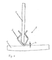
- Fig. 1 shows a device 5 according to one embodiment.
- the device 5 is designed as a welding gap clip 2.
- a first component 1 and a second component 3 can be seen, which are to be welded together.
- the welding gap clamp 2 is arranged or clamped on it, so that the welding gap clamp 2 remains fixed independently on the second component 3 during the adhesive welding.
- At least two welding gap clamps 2 are normally attached to the welding part so that the part can not tip over.
- Welding gap brackets 2 are provided at a smaller distance at one of the two first and second components 1, 3.
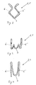
- Fig. 2 shows a Sch obtainspaltklammer 2 according to one embodiment.
- the welding gap clamp 2 is in contrast to the in FIG. 3 and FIG. 4 embodiments referred to as "normal” or “simple” welding gap clip 2. It has a first leg section 6 and a second leg section 6 ', which is designed and arranged mirror-symmetrically to the first leg section 6.
- the first leg portion 6 and the second leg portion 6 ' are resilient, so that between the first leg portion 6 and the second leg portion 6' that the second component 3 (see Fig. 1 ) can be clamped or fixed.
- the welding gap clip 2 has a section 7, which acts as a spacer between the first component 1 and the second component 3 and thus provides the welding gap 4. When welding, section 7 is in the welding zone.
- the "opening angle" of the weld gap clamp is at least twice the angle of seam preparation of the component to prevent the weld gap clip from abutting the desired location. For example, an opening angle of 90 ° is suitable for common 45 ° seam preparation.
- the welding gap clamp is made of a wire, which consists of a filler metal matched to the respective component. Furthermore, the thickness of the wire or the material thickness of the welding gap clip 2 essentially corresponds to the welding gap 4 required during welding.
- the wire used for the welding gap clip 2 shown here has a diameter of 2.0 mm. However, according to the intended use, the wire can also have any other diameter, for example a diameter of 2.4 mm.
- Fig. 3 shows a welding gap clip 2 according to another embodiment. Unlike the in Fig. 2 In the embodiment shown, this embodiment is referred to as a "double" welding gap clip 2. While the in Fig. 2 illustrated "simple" welding gap clip 2 is used for normal welding parts, the “double" welding gap clip 2 shown here can be used for particularly heavy welding parts.
- the "double" Sch spaspaltklammer 2 has a first leg portion 6 and a second leg portion 6 '. Between the first leg portion 6 and the second leg portion 6 ', the portion 7 is arranged, which is located in the welding zone during welding. The section 7 is formed in the embodiment shown here M-shaped. Also, the "double" welding gap clip 2 is resilient, so that it is independently fixed to a component to be welded, which is clamped between the first leg portion 6 and the second leg portion 6 '.
- FIG. 4 a welding gap clip 2 according to yet another embodiment.
- the welding gap clip 2 shown here likewise has a first leg section 6 and a second leg section 6 ', between which a component to be welded can be clamped.
- the portion 7, which is located during welding in the welding zone but not M-shaped but U-shaped.
- the welding gap clip 2 shown here is also produced in a spring-elastic manner from a wire which consists of a welding filler material.
- FIGS. 2, 3 and 4 Embodiments shown are suitable for both sheets and pipes of different wall thicknesses and seam preparations.
- other forms of the welding gap clip 2 are possible.
- the device 5 in a different form, which does not necessarily correspond to a clip but in another way to the component to be welded, for. B. by means of press fit or the like, can be fixed and acts as a spacer with a section.
- the welding nip bracket 2 may be made in various sizes according to the different sheet thicknesses and different materials according to the welded parts.
- FIG. 1 is shown, many high quality steel weldments are preheated between the Sch whospaltklammern 2 before welding with a burner and then stapled between the Sch whospaltklammern 2.
- the welding gap clamps 2 are no longer needed for positioning and can be ablated or fused with a burner during preheating of the remaining component. A melted welding gap clip 2 can be welded over.
- the stitching seams on the welded parts are usually sanded anyway, the Wegschleifen the welding gap clip 2 and the rest of the welding gap clip 2 after melting can be carried out in this operation with.
- the welding gap clamps 2 or the molten residues are not removed before welding, they melt completely or partially during welding.
- the possible resulting error is less than the error that may arise in a non-sharpened stapling. It is also possible to place several devices according to the invention next to one another in order to realize longer weld seams.
Landscapes
- Engineering & Computer Science (AREA)
- Physics & Mathematics (AREA)
- Mechanical Engineering (AREA)
- Plasma & Fusion (AREA)
- Optics & Photonics (AREA)
- Arc Welding In General (AREA)
- Connection Of Plates (AREA)
Applications Claiming Priority (1)
| Application Number | Priority Date | Filing Date | Title |
|---|---|---|---|
| DE202010015809U DE202010015809U1 (de) | 2010-11-24 | 2010-11-24 | Schweißspaltklammer |
Publications (2)
| Publication Number | Publication Date |
|---|---|
| EP2457686A2 true EP2457686A2 (fr) | 2012-05-30 |
| EP2457686A3 EP2457686A3 (fr) | 2013-12-25 |
Family
ID=43797174
Family Applications (1)
| Application Number | Title | Priority Date | Filing Date |
|---|---|---|---|
| EP11184898.2A Withdrawn EP2457686A3 (fr) | 2010-11-24 | 2011-10-12 | Dispositif d'espacement prédéfini de pièces en prévision d'un soudage, utilisation d'un tel dispositif et procédé de soudage d'un premier composant et d'un second composant |
Country Status (2)
| Country | Link |
|---|---|
| EP (1) | EP2457686A3 (fr) |
| DE (1) | DE202010015809U1 (fr) |
Citations (2)
| Publication number | Priority date | Publication date | Assignee | Title |
|---|---|---|---|---|
| US2046088A (en) * | 1936-04-08 | 1936-06-30 | Scovill Manufacturing Co | Welding rod |
| US2578360A (en) * | 1949-03-28 | 1951-12-11 | Arthur R Jubenville | Electrical connector |
Family Cites Families (4)
| Publication number | Priority date | Publication date | Assignee | Title |
|---|---|---|---|---|
| US1909229A (en) * | 1930-12-29 | 1933-05-16 | Raymond D Sullivan | Method of welding metallic structures |
| US3210068A (en) * | 1962-04-30 | 1965-10-05 | Continental Oil Co | Magnetic spacing tool |
| JPS5933478B2 (ja) * | 1981-01-28 | 1984-08-16 | 日本鋼管株式会社 | 鋼製円筒形構造物の積重ね組立用治具及びその組立用治具を使用した組立工法 |
| JP4908476B2 (ja) * | 2007-10-12 | 2012-04-04 | 日立建機株式会社 | T型継手の溶接方法 |
-
2010
- 2010-11-24 DE DE202010015809U patent/DE202010015809U1/de not_active Expired - Lifetime
-
2011
- 2011-10-12 EP EP11184898.2A patent/EP2457686A3/fr not_active Withdrawn
Patent Citations (2)
| Publication number | Priority date | Publication date | Assignee | Title |
|---|---|---|---|---|
| US2046088A (en) * | 1936-04-08 | 1936-06-30 | Scovill Manufacturing Co | Welding rod |
| US2578360A (en) * | 1949-03-28 | 1951-12-11 | Arthur R Jubenville | Electrical connector |
Also Published As
| Publication number | Publication date |
|---|---|
| EP2457686A3 (fr) | 2013-12-25 |
| DE202010015809U1 (de) | 2011-03-24 |
Similar Documents
| Publication | Publication Date | Title |
|---|---|---|
| EP3826795B1 (fr) | Dispositif et procédé de soudage bout à bout de pièces | |
| DE102005004787B4 (de) | Verwendung eines Bleches und Verfahren zur Herstellung einer Laserschweißnaht mit verkleinerten Endkrater | |
| DE102019114446A1 (de) | System und Verfahren zum Verschweißen von zwei thermoplastischen Werkstücken | |
| DE102019100651A1 (de) | Widerstandspunktschweißverfahren | |
| EP3030372B1 (fr) | Procédé de fabrication d'une liaison soudée | |
| EP2106305B1 (fr) | Dispositif de dressage à la flamme | |
| EP2148758A2 (fr) | Procédé et dispositif pour l'assemblage permanent de pièces en matériau métallique thermofusible | |
| DE3035437C2 (de) | Verfahren zum Befestigen eines aus schwer widerstandsschweißbarem Werkstoff bestehenden Ausgleichsgewichts an einem ebenfalls aus schwer schweißbarem Werkstoff bestehenden Rotor und Schweißvorrichtung hierfür | |
| DE102012015241A1 (de) | Verfahrenskombination zum Widerstandsschweißen | |
| WO2018224212A1 (fr) | Procédé de fabrication d'un composé d'éléments structuraux et composé d'éléments structuraux | |
| WO2015176947A1 (fr) | Procédé d'assemblage de pièces par soudage laser | |
| WO2013021053A1 (fr) | Procédé et dispositif pour relier rapidement une extrémité d'une bande métallique à un début d'une autre bande métallique | |
| CH678538A5 (en) | Hand arc welding of rail line butts - butting ends are cut with vertical ends facing each other and are preheated | |
| DE102014017563A1 (de) | Vorrichtung und Verfahren zum Fügen zweier Werkstücke mittels Laserschweißen | |
| EP1506834A1 (fr) | Méthode, dispositif de soudage et matériau de soudage pour souder un joint entre deux pièces, en particulier pour un appareil de mesure de niveau | |
| CH708916A2 (de) | Hybridschweissverfahren, -vorrichtung und -system für vertikal versetzte Komponenten. | |
| DE102015006421A1 (de) | Verfahren und Vorrichtung zum Fügen von Bauteilen | |
| DE69600474T2 (de) | Verfahren und Vorrichtung zum Verbinden von Kreuzungsschienen | |
| DE10351779B3 (de) | Verfahren zum Laserstrahlschweissen mittels vorherigem Heften | |
| DE10304709B4 (de) | Verfahren und Vorrichtung zum Laser-Hybridschweißen | |
| DE102012021766B4 (de) | Schweißanordnung insbesondere für den Karosseriebau | |
| DE102008057677B4 (de) | Verfahren und Anordnung zur Herstellung einer Schweißnaht sowie Fügestelle von zwei zumindest teilweise mit einem Überlappungsbereich übereinander angeordneten Werkstücken | |
| DE202018006370U1 (de) | Vorrichtung zum Stumpfschweißen von Werkstücken | |
| DE102008036864A1 (de) | Stranggepresstes Formteil sowie Verfahren zur Herstellung eines solchen Formteiles | |
| DE102015100935A1 (de) | Verfahren zum Verschweißen von mindestens zwei Bauteilen aus Metall |
Legal Events
| Date | Code | Title | Description |
|---|---|---|---|
| PUAI | Public reference made under article 153(3) epc to a published international application that has entered the european phase |
Free format text: ORIGINAL CODE: 0009012 |
|
| AK | Designated contracting states |
Kind code of ref document: A2 Designated state(s): AL AT BE BG CH CY CZ DE DK EE ES FI FR GB GR HR HU IE IS IT LI LT LU LV MC MK MT NL NO PL PT RO RS SE SI SK SM TR |
|
| AX | Request for extension of the european patent |
Extension state: BA ME |
|
| 17P | Request for examination filed |
Effective date: 20121107 |
|
| PUAL | Search report despatched |
Free format text: ORIGINAL CODE: 0009013 |
|
| AK | Designated contracting states |
Kind code of ref document: A3 Designated state(s): AL AT BE BG CH CY CZ DE DK EE ES FI FR GB GR HR HU IE IS IT LI LT LU LV MC MK MT NL NO PL PT RO RS SE SI SK SM TR |
|
| AX | Request for extension of the european patent |
Extension state: BA ME |
|
| RIC1 | Information provided on ipc code assigned before grant |
Ipc: B23K 37/04 20060101AFI20131120BHEP Ipc: B23K 9/025 20060101ALI20131120BHEP Ipc: B23K 9/02 20060101ALI20131120BHEP |
|
| RBV | Designated contracting states (corrected) |
Designated state(s): AL AT BE BG CH CY CZ DE DK EE ES FI FR GB GR HR HU IE IS IT LI LT LU LV MC MK MT NL NO PL PT RO RS SE SI SK SM TR |
|
| 17Q | First examination report despatched |
Effective date: 20140626 |
|
| STAA | Information on the status of an ep patent application or granted ep patent |
Free format text: STATUS: EXAMINATION IS IN PROGRESS |
|
| STAA | Information on the status of an ep patent application or granted ep patent |
Free format text: STATUS: THE APPLICATION IS DEEMED TO BE WITHDRAWN |
|
| 18D | Application deemed to be withdrawn |
Effective date: 20170810 |