EP2457744B1 - Luftreifen - Google Patents
Luftreifen Download PDFInfo
- Publication number
- EP2457744B1 EP2457744B1 EP11009281.4A EP11009281A EP2457744B1 EP 2457744 B1 EP2457744 B1 EP 2457744B1 EP 11009281 A EP11009281 A EP 11009281A EP 2457744 B1 EP2457744 B1 EP 2457744B1
- Authority
- EP
- European Patent Office
- Prior art keywords
- inboard
- outboard
- longitudinal groove
- shoulder
- tread
- Prior art date
- Legal status (The legal status is an assumption and is not a legal conclusion. Google has not performed a legal analysis and makes no representation as to the accuracy of the status listed.)
- Active
Links
- 238000012360 testing method Methods 0.000 description 12
- XLYOFNOQVPJJNP-UHFFFAOYSA-N water Substances O XLYOFNOQVPJJNP-UHFFFAOYSA-N 0.000 description 12
- 230000007423 decrease Effects 0.000 description 5
- 230000003247 decreasing effect Effects 0.000 description 5
- 238000005096 rolling process Methods 0.000 description 3
- 239000010426 asphalt Substances 0.000 description 2
- 239000011324 bead Substances 0.000 description 2
- 230000000694 effects Effects 0.000 description 2
- 230000006866 deterioration Effects 0.000 description 1
- 230000008520 organization Effects 0.000 description 1
- 230000003014 reinforcing effect Effects 0.000 description 1
- 238000013112 stability test Methods 0.000 description 1
Images


Classifications
-
- B—PERFORMING OPERATIONS; TRANSPORTING
- B60—VEHICLES IN GENERAL
- B60C—VEHICLE TYRES; TYRE INFLATION; TYRE CHANGING; CONNECTING VALVES TO INFLATABLE ELASTIC BODIES IN GENERAL; DEVICES OR ARRANGEMENTS RELATED TO TYRES
- B60C11/00—Tyre tread bands; Tread patterns; Anti-skid inserts
- B60C11/03—Tread patterns
- B60C11/0304—Asymmetric patterns
-
- B—PERFORMING OPERATIONS; TRANSPORTING
- B60—VEHICLES IN GENERAL
- B60C—VEHICLE TYRES; TYRE INFLATION; TYRE CHANGING; CONNECTING VALVES TO INFLATABLE ELASTIC BODIES IN GENERAL; DEVICES OR ARRANGEMENTS RELATED TO TYRES
- B60C11/00—Tyre tread bands; Tread patterns; Anti-skid inserts
-
- B—PERFORMING OPERATIONS; TRANSPORTING
- B60—VEHICLES IN GENERAL
- B60C—VEHICLE TYRES; TYRE INFLATION; TYRE CHANGING; CONNECTING VALVES TO INFLATABLE ELASTIC BODIES IN GENERAL; DEVICES OR ARRANGEMENTS RELATED TO TYRES
- B60C11/00—Tyre tread bands; Tread patterns; Anti-skid inserts
- B60C11/03—Tread patterns
-
- B—PERFORMING OPERATIONS; TRANSPORTING
- B60—VEHICLES IN GENERAL
- B60C—VEHICLE TYRES; TYRE INFLATION; TYRE CHANGING; CONNECTING VALVES TO INFLATABLE ELASTIC BODIES IN GENERAL; DEVICES OR ARRANGEMENTS RELATED TO TYRES
- B60C11/00—Tyre tread bands; Tread patterns; Anti-skid inserts
- B60C11/03—Tread patterns
- B60C11/04—Tread patterns in which the raised area of the pattern consists only of continuous circumferential ribs, e.g. zig-zag
-
- B—PERFORMING OPERATIONS; TRANSPORTING
- B60—VEHICLES IN GENERAL
- B60C—VEHICLE TYRES; TYRE INFLATION; TYRE CHANGING; CONNECTING VALVES TO INFLATABLE ELASTIC BODIES IN GENERAL; DEVICES OR ARRANGEMENTS RELATED TO TYRES
- B60C11/00—Tyre tread bands; Tread patterns; Anti-skid inserts
- B60C11/03—Tread patterns
- B60C11/11—Tread patterns in which the raised area of the pattern consists only of isolated elements, e.g. blocks
-
- B—PERFORMING OPERATIONS; TRANSPORTING
- B60—VEHICLES IN GENERAL
- B60C—VEHICLE TYRES; TYRE INFLATION; TYRE CHANGING; CONNECTING VALVES TO INFLATABLE ELASTIC BODIES IN GENERAL; DEVICES OR ARRANGEMENTS RELATED TO TYRES
- B60C11/00—Tyre tread bands; Tread patterns; Anti-skid inserts
- B60C11/03—Tread patterns
- B60C11/13—Tread patterns characterised by the groove cross-section, e.g. for buttressing or preventing stone-trapping
-
- B—PERFORMING OPERATIONS; TRANSPORTING
- B60—VEHICLES IN GENERAL
- B60C—VEHICLE TYRES; TYRE INFLATION; TYRE CHANGING; CONNECTING VALVES TO INFLATABLE ELASTIC BODIES IN GENERAL; DEVICES OR ARRANGEMENTS RELATED TO TYRES
- B60C5/00—Inflatable pneumatic tyres or inner tubes
-
- B—PERFORMING OPERATIONS; TRANSPORTING
- B60—VEHICLES IN GENERAL
- B60C—VEHICLE TYRES; TYRE INFLATION; TYRE CHANGING; CONNECTING VALVES TO INFLATABLE ELASTIC BODIES IN GENERAL; DEVICES OR ARRANGEMENTS RELATED TO TYRES
- B60C11/00—Tyre tread bands; Tread patterns; Anti-skid inserts
- B60C11/03—Tread patterns
- B60C11/0318—Tread patterns irregular patterns with particular pitch sequence
-
- B—PERFORMING OPERATIONS; TRANSPORTING
- B60—VEHICLES IN GENERAL
- B60C—VEHICLE TYRES; TYRE INFLATION; TYRE CHANGING; CONNECTING VALVES TO INFLATABLE ELASTIC BODIES IN GENERAL; DEVICES OR ARRANGEMENTS RELATED TO TYRES
- B60C11/00—Tyre tread bands; Tread patterns; Anti-skid inserts
- B60C11/03—Tread patterns
- B60C11/0327—Tread patterns characterised by special properties of the tread pattern
- B60C11/033—Tread patterns characterised by special properties of the tread pattern by the void or net-to-gross ratios of the patterns
-
- B—PERFORMING OPERATIONS; TRANSPORTING
- B60—VEHICLES IN GENERAL
- B60C—VEHICLE TYRES; TYRE INFLATION; TYRE CHANGING; CONNECTING VALVES TO INFLATABLE ELASTIC BODIES IN GENERAL; DEVICES OR ARRANGEMENTS RELATED TO TYRES
- B60C11/00—Tyre tread bands; Tread patterns; Anti-skid inserts
- B60C11/03—Tread patterns
- B60C2011/0337—Tread patterns characterised by particular design features of the pattern
- B60C2011/0339—Grooves
- B60C2011/0341—Circumferential grooves
-
- B—PERFORMING OPERATIONS; TRANSPORTING
- B60—VEHICLES IN GENERAL
- B60C—VEHICLE TYRES; TYRE INFLATION; TYRE CHANGING; CONNECTING VALVES TO INFLATABLE ELASTIC BODIES IN GENERAL; DEVICES OR ARRANGEMENTS RELATED TO TYRES
- B60C11/00—Tyre tread bands; Tread patterns; Anti-skid inserts
- B60C11/03—Tread patterns
- B60C2011/0337—Tread patterns characterised by particular design features of the pattern
- B60C2011/0339—Grooves
- B60C2011/0341—Circumferential grooves
- B60C2011/0353—Circumferential grooves characterised by width
-
- B—PERFORMING OPERATIONS; TRANSPORTING
- B60—VEHICLES IN GENERAL
- B60C—VEHICLE TYRES; TYRE INFLATION; TYRE CHANGING; CONNECTING VALVES TO INFLATABLE ELASTIC BODIES IN GENERAL; DEVICES OR ARRANGEMENTS RELATED TO TYRES
- B60C11/00—Tyre tread bands; Tread patterns; Anti-skid inserts
- B60C11/03—Tread patterns
- B60C2011/0337—Tread patterns characterised by particular design features of the pattern
- B60C2011/0339—Grooves
- B60C2011/0358—Lateral grooves, i.e. having an angle of 45 to 90 degees to the equatorial plane
- B60C2011/0365—Lateral grooves, i.e. having an angle of 45 to 90 degees to the equatorial plane characterised by width
-
- B—PERFORMING OPERATIONS; TRANSPORTING
- B60—VEHICLES IN GENERAL
- B60C—VEHICLE TYRES; TYRE INFLATION; TYRE CHANGING; CONNECTING VALVES TO INFLATABLE ELASTIC BODIES IN GENERAL; DEVICES OR ARRANGEMENTS RELATED TO TYRES
- B60C11/00—Tyre tread bands; Tread patterns; Anti-skid inserts
- B60C11/03—Tread patterns
- B60C2011/0337—Tread patterns characterised by particular design features of the pattern
- B60C2011/0339—Grooves
- B60C2011/0358—Lateral grooves, i.e. having an angle of 45 to 90 degees to the equatorial plane
- B60C2011/0372—Lateral grooves, i.e. having an angle of 45 to 90 degees to the equatorial plane with particular inclination angles
-
- B—PERFORMING OPERATIONS; TRANSPORTING
- B60—VEHICLES IN GENERAL
- B60C—VEHICLE TYRES; TYRE INFLATION; TYRE CHANGING; CONNECTING VALVES TO INFLATABLE ELASTIC BODIES IN GENERAL; DEVICES OR ARRANGEMENTS RELATED TO TYRES
- B60C11/00—Tyre tread bands; Tread patterns; Anti-skid inserts
- B60C11/03—Tread patterns
- B60C2011/0337—Tread patterns characterised by particular design features of the pattern
- B60C2011/0339—Grooves
- B60C2011/0374—Slant grooves, i.e. having an angle of about 5 to 35 degrees to the equatorial plane
-
- B—PERFORMING OPERATIONS; TRANSPORTING
- B60—VEHICLES IN GENERAL
- B60C—VEHICLE TYRES; TYRE INFLATION; TYRE CHANGING; CONNECTING VALVES TO INFLATABLE ELASTIC BODIES IN GENERAL; DEVICES OR ARRANGEMENTS RELATED TO TYRES
- B60C11/00—Tyre tread bands; Tread patterns; Anti-skid inserts
- B60C11/03—Tread patterns
- B60C2011/0337—Tread patterns characterised by particular design features of the pattern
- B60C2011/0386—Continuous ribs
- B60C2011/0388—Continuous ribs provided at the equatorial plane
Definitions
- the present invention relates to a pneumatic tire, more particularly to an asymmetric tread pattern for passenger cars and the like capable of improving the drainage performance without sacrificing the steering stability on dry roads.
- the features of the preamble of the independent claim are known from DE 10 2008 037497 A1 .
- Asymmetric tread patterns are also known from EP 2 202 098 A1 and EP 1 552 966 A1 .
- the tread portion is provided with circumferentially-continuously-extending longitudinal grooves, and the longitudinal grooves are increased in the cross-sectional area and/or volume.
- the groove volume/area is excessively increased, there is a tendency that the road grip performance during cornering is decreased and the steering stability on dry roads is liable to deteriorate.
- the drainage performance may be improved, but deterioration of the steering stability on dry roads is inevitable.
- an object of the present invention to provide a pneumatic tire of which drainage performance is improved without sacrificing the steering stability on dry roads.
- a pneumatic tire comprises a tread portion provided with a tread pattern asymmetric about the tire equator and having an inboard tread edge and an outboard tread edge to be positioned inside and outside, respectively, of a vehicle, the tread portion provided with circumferentially-continuously-extending longitudinal grooves including an inboard shoulder longitudinal groove as nearest to the inboard tread edge and an outboard shoulder longitudinal groove as nearest to the outboard tread edge, wherein the axial distance xi from the tire equator to the inboard edge of the inboard shoulder longitudinal groove is in a range of from 27 to 33 % of the tread width between the inboard tread edge and outboard tread edge, the axial distance Xo from the tire equator to the outboard edge of the outboard shoulder longitudinal groove is in a range of from 27 to 33 % of the tread width, the axial distance Xi is less than the axial distance Xo, and a crown region defined between the inboard edge of the inboard shoulder longitudinal groove and the outboard edge of
- inboard and outboard mean as being relatively close to the center of the vehicle and far from the center of the vehicle, respectively, on the assumption than the tire is properly installed on the vehicle. In the case of the tire alone, the terms “inboard” and “outboard” are interpreted as being relatively close to the inboard tread edge and close to the outboard tread edge, respectively.
- the inboard shoulder longitudinal groove and outboard shoulder longitudinal groove get closer to a tread center region contacting with the ground during straight running, and further the sea ratio of the crown region is high.
- the inboard shoulder land region which contacts with the ground during straight running when the tire is used with a negative camber angle is increased in the rigidity, and the straight running stability on dry roads can be greatly improved.
- the normally inflated unloaded condition is such that the tire is mounted on a standard wheel rim and inflate to a standard pressure but loaded with no tire load.
- the undermentioned normally inflated loaded condition is such that the tire is mounted on the standard wheel rim and inflate to the standard pressure and loaded with the standard tire load.
- the standard wheel rim is a wheel rim officially approved or recommended for the tire by standards organizations, i.e. JATMA (Japan and Asia), T&RA (North America), ETRTO (Europe), TRAA (AUStralia),STRO (Scandinavia), ALAPA (Latin America), ITTAC (India) and the like which are effective in the area where the tire is manufactured, sold or used.
- the standard pressure and the standard tire load are the maximum air pressure and the maximum tire load for the tire specified by the same organization in the Air-pressure/Maximum-load Table or similar list.
- the standard wheel rim is the "standard rim” specified in JATMA, the "Measuring Rim” in ETRTO, the "Design Rim” in TRA or the like.
- the standard pressure is the “maximum air pressure” in JATMA, the “Inflation Pressure” in ETRTO, the maximum pressure given in the “Tire Load Limits at various cold Inflation Pressures” table in TRA or the like.
- the standard load is the "maximum load capacity" in JATMA, the “Load capacity” in ETRTO, the maximum value given in the above-mentioned table in TRA or the like. In case of passenger car tires, however, the standard pressure and standard tire load are uniformly defined by 180 kPa and 88 % of the maximum tire load, respectively.
- the pneumatic tire 1 comprises a tread portion 2, a pair of sidewall portions, a pair of bead portions, a carcass extending between the bead portions, and a tread reinforcing belt disposed radially outside the carcass in the tread portion as usual.
- the pneumatic tire 1 is a summer tire for passenger cars.
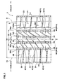
- the tread portion 2 is provided with longitudinal grooves 3 extending continuously in the tire circumferential direction, and transverse grooves 4 extending crosswise to the longitudinal grooves 3 so as to form a tread pattern which is left-right asymmetry about the tire equator C.
- the tire has an intended/designed mount position relative to the vehicle, namely, it is specified that which sidewall portion is to be positioned outside.
- the intended mount position is indicated in the sidewall portion by the use of words (for example "INSIDE” and/or "OUTSIDE") and/or symbol such as arrow.
- the tire therefore has an inboard tread edge 2i to be positioned inside and an outboard tread edge 2o to be positioned outside in relation to the vehicle.
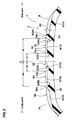
- the undermentioned tread width TW is the axial distance measured between the tread edges 2i and 2o under the normally inflated unloaded condition.
- the longitudinal grooves 3 are at least two grooves each extending straight in the tire circumferential direction and having a width W1 which is preferably set in a range of about 3 to 7 % of the tread width TW, and a depth D1 which is preferably set in a range of about 3 to 6 % of the tread width TW.
- Such straight grooves are preferable because they can provide good drainage during straight running and during cornering.
- the longitudinal grooves 3 include: an inboard shoulder longitudinal groove 3A as nearest to the inboard tread edge 2i; and an outboard shoulder longitudinal groove 3B as nearest to the outboard tread edge 2o.
- the longitudinal grooves 3 further include: an inboard central longitudinal groove 3C disposed between the inboard shoulder longitudinal groove 3A and the tire equator C; and an outboard center longitudinal groove 3D disposed between the outboard shoulder longitudinal groove 3B and the tire equator C.
- the tread portion 2 is divided into: an inboard shoulder land region 5A defined by the inboard shoulder longitudinal groove 3A and the inboard tread edge 2i; an outboard shoulder land region 5B defined by the outboard shoulder longitudinal groove 3B and the outboard tread edge 2o; an inboard middle land region 5C defined by the inboard shoulder longitudinal groove 3A and the inboard central longitudinal groove 3C; an outboard middle land region 5D defined by the outboard shoulder longitudinal groove 3B and the outboard center longitudinal groove 3D; and a central land region 5E defined by the inboard central longitudinal groove 3c and the outboard center longitudinal groove 3D.
- the crown region defined between the inboard edge 3Ao of the inboard shoulder longitudinal groove 3A and the outboard edge 3Bo of the outboard shoulder longitudinal groove 3B has a sea ratio in a range of from 30 to 50 %.
- the sea ratio means the ratio SG/SL of the total grooved area SG to the gross area SL of the region concerned measured at the tread surface.
- the axial distance Xi from the tire equator C to the inboard edge 3Ao of the inboard shoulder longitudinal groove 3A is set in a range of from 27 to 33 % of the tread width TW
- the axial distance Xo from the tire equator C to the outboard edge 3Bo of the outboard shoulder longitudinal groove 3B is set in a range of from 27 to 33 % of the tread width TW.
- the inboard shoulder longitudinal groove 3A and outboard shoulder longitudinal groove 3B shift toward a tread center region which contacts with the ground during straight running as well as during cornering. Further, the sea ratio of the crown region therebetween is increased. Therefore, water film existing beneath the tread central region can be effectively discharged.
- the above-mentioned axial distance Xi is set to be less than the axial distance Xo in order to increase the rigidity of the inboard shoulder land region 5A which contacts with the ground during straight running when the tire is installed on a vehicle with a negative camber angle, and thereby to improve the straight running stability on dry roads.
- the axial distances Xi and Xo are less than 27 % of the tread width TW, the rigidity in the inboard shoulder land region 5A and outboard shoulder land region 5B is increased and the difference from the rigidity in the crown region is also increased. As a result, there is a possibility that the steering stability is deteriorated. If the axial distances Xi and Xo are more than 33 % of the tread width TW, it is difficult to obtain the above-mentioned advantage.
- the axial distance Xi and distance Xo are preferably set in a range of not less than 28 %, but not more than 32 % of the tread width TW.
- the axial distance Xi is not more than 98 %, more preferably not more than 97 %, but, not less than 92 %, more preferably not less than 93 % of the distance Xo. If more than 98 %, it become difficult to obtain the above-mentioned advantage. If less than 92 %, the rigidity of the inboard shoulder land region 5A is increased, and the rigidity difference between the inboard shoulder land region 5A and outboard shoulder land region 5B increases. As a result, there is a possibility that steering stability on dry roads is deteriorated.
- the sea ratio of the crown region is less than 30 %, the drainage during straight running is deteriorated. If the sea ratio of the crown region exceeds 50 %, the rigidity is excessively decreased in the tread central region, and there is a possibility that straight running stability on dry roads is deteriorated. From this standpoint, the sea ratio is preferably not less than 35 %, more preferably not less than 37 %, but not more than 45 %, more preferably not more than 43 %.
- the width W1a of the inboard shoulder longitudinal groove 3A is set to be more than the width W1b of the outboard shoulder longitudinal groove 3B.
- Such wider inboard shoulder longitudinal groove 3A can eliminate more water from the tread face near the inboard shoulder longitudinal groove 3A when the tire 1 is installed on a vehicle with a negative camber angle and runs straight during which the tread face near the inboard shoulder longitudinal groove 3A mainly contacts with the ground, or when the tire 1 becomes on a closer side to the turning center during cornering. Thus, it is possible to improve the drainage performance of the tire under such situation.
- the groove width W1a is preferably set to be not less than 101 %, more preferably not less than 103 % of the groove width wlb.
- the groove width W1a is preferably set to be not more than 120 %, more preferably not more than 110 % of the groove width W1b.
- the axial distance Yi from the tire equator C to the inboard edge 3Co of the inboard central longitudinal groove 3C is set to be less than the axial distance Yo from the tire equator C to the outboard edge 3Do of the outboard center longitudinal groove 3D.
- the rigidity of the inboard middle land region 5C is relatively increased, and the straight running stability on dry roads can be effectively improved when the camber angle is negative because the inboard middle land region 5C can more contact with the ground during straight running.
- the axial distance Yi is not more than 95 %, more preferably not more than 90 %, but not less than 80 %, more preferably not less than 85 % of the axial distance Yo. If the axial distance Yi is more than 95 %, it is difficult to derive the above explained advantageous effect. If the axial distance Yi is less than 80 %, the rigidity difference between the inboard middle land region 5C and outboard middle land region 5D increases, and there is a possibility that the steering stability on dry roads is deteriorated.
- transverse grooves 4 are: inboard shoulder transverse grooves 11 disposed in the inboard shoulder land region 5A; outboard shoulder transverse grooves 12 disposed in the outboard shoulder land region 5B; inboard middle transverse grooves 13 disposed in the inboard middle land region 5C; outboard middle transverse grooves 14 disposed in the outboard middle land region 5D; and central transverse grooves 15 disposed in the central land region 5E.
- these transverse grooves 11-15 each have a width W2 of about 2 to 3 % of the tread width TW, and a depth D2 of about 5 to 8 % of the tread width TW.
- the inboard shoulder transverse grooves 11 extend toward the tire equator from the outside of the inboard tread edge 2i, while slightly inclining to one circumferential direction and keeping a substantially constant groove width w2 to smoothly lead water to the inboard tread edge 2i.
- the angle ⁇ 1 of the inboard shoulder transverse grooves 11 with respect to the tire circumferential direction is preferably set in a range of not less than 75 degrees, more preferably not less than 80 degrees, but not more than 90 degrees.
- angle ⁇ 1 is less than 75 degrees, the smooth leading of water utilizing the rolling of the tire becomes difficult. If the angle ⁇ 1 is more than 90 degrees, the rigidity in the inboard shoulder land region 5A decreases, and there is a possibility that the straight running stability on dry roads is deteriorated.
- the outboard ends 11i of the inboard shoulder transverse grooves 11 terminate, without reaching to the inboard shoulder longitudinal groove 3A, whereby, in the inboard shoulder land region 5A, there is formed a circumferentially continuously extending rib 21 abutting on the inboard shoulder longitudinal groove 3A.
- the rigidity in the inboard shoulder land region 5A is increased, and the straight running stability on dry roads can be greatly improved when the tire is used with a negative camber angle.
- the axial minimum distance L1 between the outboard ends 11i of the inboard shoulder transverse grooves 11 and the inboard edge 3Ao of the inboard shoulder longitudinal groove 3A is preferably set to be not less than 80 %, more preferably not less than 90 % of the width W1a of the inboard shoulder longitudinal groove 3A.
- the axial minimum distance L1 is preferably not more than 120 %, more preferably not more than 110 % of the groove width W1a.
- inner shoulder narrow grooves 16 each extending from one of the outboard ends 11i of the inboard shoulder transverse grooves 11 to the circumferentially adjacent inboard shoulder transverse groove 11, while inclining toward the inboard tread edge 2i at a small angle with respect to the tire circumferential direction.
- Such inner shoulder narrow grooves 16 can provide a zigzag edge having a saw-tooth appearance for the rib 21, and the zigzag edge can break water film. As a result, the drainage performance can be improved.
- an inboard shoulder link groove 17 which circumferentially connects the inboard ends 11o of the circumferentially adjacent inboard shoulder transverse grooves 11.
- the inboard shoulder link groove 17 can mitigate distortion occurring in the inboard shoulder land region 5A, and helps to control the occurrence of uneven wear.
- the outboard shoulder transverse grooves 12 extend from the outboard shoulder longitudinal groove 3B toward the outboard tread edge 2o, while slightly inclining to one circumferential direction.
- the inboard ends 12i of the outboard shoulder transverse grooves 12 are opened to the outboard shoulder longitudinal groove 3B.
- the outboard shoulder transverse grooves 12 extend beyond the outboard tread edge 2o and then terminate. Accordingly, the outboard ends 12o thereof are positioned outside the outboard tread edge 2o.
- water film existing beneath the outboard shoulder land region 5B and water existing in the outboard shoulder longitudinal groove 3B can be effectively led to the outboard tread edge 2i and discharged.
- the angle ⁇ 2 of the outboard shoulder transverse grooves 12 with respect to the tire circumferential direction is preferably set in a range of not less than 80 degrees, but not more than 90 degrees for the similar view to the angle ⁇ 1.
- an outer shoulder link groove 18 circumferentially connecting the outboard ends 12o of the outboard shoulder transverse grooves 12.
- the outer shoulder link groove 18 can mitigate distortion occurring in the outboard shoulder land region 5, and helps to control the occurrence of uneven wear.
- the outboard shoulder land region 5B is divided into outer shoulder blocks 22 having rectangular configurations longer in the tire axial direction than in the tire circumferential direction in order to increase the axial rigidity and thereby to improve the steering stability on dry roads.
- the outboard shoulder transverse groove 12 is partially provided near the outboard shoulder longitudinal groove 3B with a tie bar 28 protruding from the groove bottom within the groove so as to extend from one of opposite groove walls to the other in order to increase the tread rigidity in the outboard shoulder land region 5B and thereby further improve the steering stability on dry roads.
- the inboard middle transverse grooves 13 are disposed between the inboard shoulder longitudinal groove 3A and the inboard central longitudinal groove 3C, and are inclined steeply when compare with the inboard shoulder transverse grooves 11.
- the angle ⁇ 3 of the inboard middle transverse grooves 13 with respect to the tire circumferential direction is preferably set in a range of not less than 25 degrees, more preferably not less than 30 degrees, but not more than 50 degrees, more preferably not more than 45 degrees in order to improve the rigidity and drainage in the inboard middle land region 5C in a well balanced manner.
- the width W2 of the inboard middle transverse grooves 13 gradually increases from the inboard central longitudinal groove 3C to the inboard shoulder longitudinal groove 3A.
- the inboard middle transverse grooves 13 include: first inboard middle transverse grooves 13A; and second inboard middle transverse grooves 13B which are arranged alternately in the tire circumferential direction.
- the first inboard middle transverse groove 13A has an inboard end 13Ao opened to the inboard shoulder longitudinal groove 3A and an outboard end 13Ai opened to the inboard central longitudinal groove 3C.
- the second inboard middle transverse grooves 13B has an inboard end 13Bo opened to the inboard shoulder longitudinal groove 3A and an outboard end 13Bi terminated without reaching to the inboard central longitudinal groove 3C.
- the inboard middle land region 5C is divided into inboard middle blocks 23 having a parallelogram configuration longer in the tire circumferential direction than in the tire axial direction.
- the circumferential pitch P1 of the first inboard middle transverse grooves 13A is more than the circumferential pitch P2 of the inboard shoulder transverse grooves 11.
- the circumferential pitch P1 can be defined as the circumferential distance between the intersecting points 31 of the inboard shoulder longitudinal groove 3A with the groove edges of the first inboard middle transverse grooves 13A on one side in the tire circumferential direction.
- the circumferential pitch P2 can be defined as the circumferential distance between the intersecting points 32 of the inboard tread edge 2i with the groove edges of the inboard shoulder transverse grooves 11 on one side in the tire circumferential direction.
- the drainage can be increased by the first inboard middle transverse grooves 13A, while controlling decrease in the tread rigidity in the inboard middle land region 5C.
- the circumferential pitch P1 is preferably set to be not less than 150 %, more preferably not less than 170 % of the circumferential pitch P2.
- the circumferential pitch P1 is preferably not more than 250 %, more preferably not more than 220 % of the circumferential pitch P2.
- the outboard middle transverse grooves 14 extend from the outboard shoulder longitudinal groove 3B to the outboard center longitudinal groove 3D, while inclining to one circumferential direction.
- the outboard middle transverse groove 14 has an outboard end 14o opened to the outboard shoulder longitudinal groove 3B and an inboard end 14i opened to the outboard center longitudinal groove 3D.
- the angle ⁇ 4 of the outboard middle transverse grooves 14 with respect to the tire circumferential direction is set to be less than the angle ⁇ 2 of the outboard shoulder transverse grooves 12 with respect to the tire circumferential direction.
- the angle ⁇ 4 is set in a range of about 40 to 70 degrees.
- Such outboard middle transverse grooves 14 can lead water film existing beneath the outboard middle land region 5D to the outboard tread edge 2o effectively utilizing the rolling of the tire.
- the outboard middle transverse grooves 14 include:
- the outboard middle land region 5D is divided into outboard middle blocks 24 having a substantially parallelogram configuration in order to provide axial rigidity and circumferential rigidity in a well balance manner, which helps to improve the straight running stability on dry roads and steering stability.
- the central transverse grooves 15 include first central transverse grooves 15A and second central transverse grooves 15B which are arraigned alternately in the circumferential direction.
- the first central transverse groove 15A has an outboard end 15Ao opened to the outboard center longitudinal groove 3D and an inboard end 15Ai positioned between the tire equator C and the inboard central longitudinal groove 3C.
- the second central transverse groove 15B has an outboard end 15Bo opened to the outboard center longitudinal groove 3D and an inboard end 15Bi positioned between the outboard center longitudinal groove 3D and the tire equator C.
- the second central transverse groove 15B is wider than the first central transverse groove 15A.
- the central land region 5E is not provided with grooves extending across its entire width, therefore, the central land region 5E can function as an almost circumferentially continuously extending rib.
- the first and second central transverse grooves 15A and 15B prevent the rigidity of the central land region 5E from excessively decreasing, which helps to increase the drainage while maintaining the straight running stability and steering stability.
- the angle ⁇ 5 of the central transverse grooves 15 is less than the angle ⁇ 2 of the outboard shoulder transverse grooves 12 and less than the angle ⁇ 4 of the outboard middle transverse grooves 14.
- the angle ⁇ 5 is set in a range of from about 25 to 60 degrees.
- Such central transverse grooves 15 can effectively lead water film existing beneath the central land region 5E to the outboard tread edge 2o by utilizing the rolling of the tire.
- the first central transverse grooves 15A are respectively aligned with the first outboard middle transverse grooves 14A.
- the second central transverse grooves 15B are respectively aligned with the second outboard middle transverse grooves 14B.
- test tires of size 245/50 R18 (rim size 18X8J) having longitudinal grooves and transverse grooves shown in Table 1 were prepared and tested.
- tread width TW 183 mm longitudinal grooves: groove depth D1: 8 mm (4.1 % of TW) transverse grooves: width w2: 3 to 5 mm (1.6 to 2.7 % of TW) depth D2: 5 to 7 mm (2.7 to 3.8 % of TW) inboard shoulder transverse grooves:
- test car was run on a dry asphalt road in a tire test course, and the test driver evaluated the steering stability into ranks based on the steering response, rigidity and grip during cornering, wherein the higher the rank number, the better the steering stability on dry roads.
- rank number the higher the rank number
Landscapes
- Engineering & Computer Science (AREA)
- Mechanical Engineering (AREA)
- Tires In General (AREA)
Claims (10)
- Luftreifen, der einen Laufflächenabschnitt (2) umfasst, der mit einem Laufflächenprofil versehen ist, das um den Reifenäquator (C) herum asymmetrisch ist, und der eine innen liegende Laufflächenkante (2i) und eine außen liegende Laufflächenkante (2o) aufweist, die jeweils auf der Innenseite bzw. der Außenseite eines Fahrzeugs zu positionieren sind,
wobei der Laufflächenabschnitt mit sich in Umfangsrichtung durchgehend erstreckenden Längsrillen (3) versehen ist, die eine innen liegende Schulterlängsrille (3A) am nächsten bei der innen liegenden Laufflächenkante (2i) und eine außen liegende Schulterlängsrille (3B) am nächsten bei der außen liegenden Laufflächenkante (2o) umfassen,
dadurch gekennzeichnet, dass
der axiale Abstand Xi von dem Reifenäquator (C) zu der innen liegenden Kante (3Ao) der innen liegenden Schulterlängsrille (3A) in einem Bereich von 27 bis 33 % einer Laufflächenbreite (Tw) zwischen der innen liegenden Laufflächenkante (2i) und der außen liegenden Laufflächenkante (2o) liegt,
der axiale Abstand Xo von dem Reifenäquator (C) zu der außen liegenden Kante (3Bo) der außen liegenden Schulterlängsrille (3B) in einem Bereich von 27 bis 33 % der Laufflächenbreite (TW) liegt,
der axiale Abstand Xi kleiner als der axiale Abstand Xo ist, und
ein Kronenbereich, der zwischen einer innen liegenden Kante (3Ao) der innen liegenden Schulterlängsrille (3A) und einer außen liegenden Kante (3Bo) der außen liegenden Schulterlängsrille (3B) definiert ist, ein See-Verhältnis in einem Bereich von 30 bis 50 % aufweist,
wobei
ein innen liegender Schulterlandbereich (5A) des Laufflächenabschnitts, der zwischen der innen liegenden Schulterlängsrille (3A) und der innen liegenden Laufflächenkante (2i) definiert ist, mit innen liegenden Schulterquerrillen (11) versehen ist, die sich unter einem Winkel von 75 bis 90 Grad mit Bezug auf die Umfangsrichtung des Reifens von der Außenseite der innen liegenden Laufflächenkante (2i) zu der innen liegenden Schulterlängsrille (3A) hin erstrecken, aber enden, ohne diese zu erreichen. - Luftreifen nach Anspruch 1, wobei
ein außen liegender Schulterlandbereich (5B) des Laufflächenabschnitts, der zwischen der außen liegenden Schulterlängsrille (3B) und der außen liegenden Laufflächenkante (2o) definiert ist, mit außen liegenden Schulterquerrillen (12) versehen ist, die sich unter einem Winkel von 80 bis 90 Grad mit Bezug auf die Umfangsrichtung des Reifens von der außen liegenden Schulterlängsrille (3B) zu der außen liegenden Laufflächenkante (2o) hin erstrecken und an einer Position jenseits der außen liegenden Laufflächenkante (2o) enden. - Luftreifen nach einem der Ansprüche 1-2, wobei
die Breite der innen liegenden Schulterlängsrille (3A) größer als die Breite der außen liegenden Schulterlängsrille (3B) ist. - Luftreifen nach einem der Ansprüche 1-3, wobei
die Längsrillen (3) ferner umfassen: eine innen liegende zentrale Längsrille (3C), die zwischen dem Reifenäquator und der innen liegenden Schulterlängsrille (3A) angeordnet ist; und eine außen liegende zentrale Längsrille (3D), die zwischen dem Reifenäquator und der außen liegenden Schulterlängsrille (3B) angeordnet ist, und
der axiale Abstand Yi von dem Reifenäquator zu der innen liegenden Kante (3Co) der innen liegenden zentralen Längsrille (3C) kleiner als der axiale Abstand Yo von dem Reifenäquator zu der außen liegenden Kante (3Do) der außen liegenden zentralen Längsrille (3D) ist. - Luftreifen nach Anspruch 4, wobei
ein innen liegender mittlerer Landbereich (5c) des Laufflächenabschnitts, der zwischen der innen liegenden zentralen Längsrille (3C) und der innen liegenden Schulterlängsrille (3A) definiert ist, mit innen liegenden mittleren Querrillen (13) versehen ist, die sich unter einem Winkel von 25 bis 50 Grad mit Bezug auf die Umfangsrichtung des Reifens erstrecken, und
die innen liegenden mittleren Querrillen (13) umfassen:erste innen liegende mittlere Querrillen (13A), die jeweils ein innen liegendes Ende (13Ao) aufweisen, das zu der innen liegenden Schulterlängsrille (3A) geöffnet ist; und ein außen liegendes Ende (13Ai), das zu der innen liegenden zentralen Längsrille (3C) geöffnet ist, undzweite innen liegende mittlere Querrillen (13B), die ein innen liegendes Ende (13Bo) aufweisen, das zu der innen liegenden Schulterlängsrille (3A) geöffnet ist, und ein außen liegendes Ende (13Bi), das endet, ohne die innen liegende zentrale Längsrille (3C) zu erreichen. - Luftreifen nach Anspruch 5, wobei
der Umfangsteilungsabstand (P1) der ersten innen liegenden mittleren Querrillen (13A) größer als der Umfangsteilungsabstand (P2) der innen liegenden Schulterquerrillen (11) ist. - Luftreifen nach einem der Ansprüche 1-6, der an einem Fahrzeug angebracht ist, das einen negativen Sturzwinkel aufweist.
- Luftreifen nach einem der Ansprüche 1-7, wobei
der axiale Abstand Xi von dem Reifenäquator (C) zu der innen liegenden Kante (3Ao) der innen liegenden Schulterlängsrille (3A) in einem Bereich von 28 bis 32 % einer Laufflächenbreite (Tw) zwischen der innen liegenden Laufflächenkante (2i) und der außen liegenden Laufflächenkante (2o) liegt. - Luftreifen nach einem der Ansprüche 1-8, wobei
der axiale Abstand Xo von dem Reifenäquator (C) zu der außen liegenden Kante (3Bo) der außen liegenden Schulterlängsrille (3B) in einem Bereich von 28 bis 32 % der Laufflächenbreite (TW) liegt. - Luftreifen nach einem der Ansprüche 1-9, wobei
das See-Verhältnis des Kronenbereichs in einem Bereich von 35 bis 45 % und bevorzugt in einem Bereich von 37 bis 43 % liegt.
Applications Claiming Priority (1)
| Application Number | Priority Date | Filing Date | Title |
|---|---|---|---|
| JP2010267115A JP5118742B2 (ja) | 2010-11-30 | 2010-11-30 | 空気入りタイヤ |
Publications (3)
| Publication Number | Publication Date |
|---|---|
| EP2457744A2 EP2457744A2 (de) | 2012-05-30 |
| EP2457744A3 EP2457744A3 (de) | 2012-12-12 |
| EP2457744B1 true EP2457744B1 (de) | 2015-05-27 |
Family
ID=45065600
Family Applications (1)
| Application Number | Title | Priority Date | Filing Date |
|---|---|---|---|
| EP11009281.4A Active EP2457744B1 (de) | 2010-11-30 | 2011-11-23 | Luftreifen |
Country Status (5)
| Country | Link |
|---|---|
| US (1) | US9174492B2 (de) |
| EP (1) | EP2457744B1 (de) |
| JP (1) | JP5118742B2 (de) |
| KR (1) | KR101788879B1 (de) |
| CN (1) | CN102529593B (de) |
Families Citing this family (25)
| Publication number | Priority date | Publication date | Assignee | Title |
|---|---|---|---|---|
| CN104936796B (zh) * | 2013-03-15 | 2017-03-29 | 横滨橡胶株式会社 | 零压轮胎 |
| JP5913238B2 (ja) * | 2013-09-09 | 2016-04-27 | 住友ゴム工業株式会社 | 空気入りタイヤ |
| JP6097238B2 (ja) * | 2014-03-11 | 2017-03-15 | 住友ゴム工業株式会社 | 空気入りタイヤ |
| JP6047137B2 (ja) | 2014-11-20 | 2016-12-21 | 住友ゴム工業株式会社 | 空気入りタイヤ |
| JP6126571B2 (ja) * | 2014-12-09 | 2017-05-10 | 住友ゴム工業株式会社 | 空気入りタイヤ |
| JP6441096B2 (ja) * | 2015-01-29 | 2018-12-19 | 株式会社ブリヂストン | 空気入りタイヤ |
| JP6391483B2 (ja) * | 2015-01-29 | 2018-09-19 | 株式会社ブリヂストン | 空気入りタイヤ |
| EP3498498B1 (de) | 2015-01-30 | 2021-03-24 | Bridgestone Corporation | Luftreifen |
| JP6814638B2 (ja) | 2015-02-04 | 2021-01-20 | 株式会社ブリヂストン | 空気入りタイヤ |
| JP6348868B2 (ja) * | 2015-04-09 | 2018-06-27 | 住友ゴム工業株式会社 | 空気入りタイヤ |
| JP6482396B2 (ja) | 2015-06-15 | 2019-03-13 | 株式会社ブリヂストン | 空気入りタイヤ |
| JP6614949B2 (ja) * | 2015-12-03 | 2019-12-04 | Toyo Tire株式会社 | 空気入りタイヤ |
| AU201615825S (en) * | 2016-07-26 | 2016-11-15 | Kumho Tire Co | Tyre for an automobile |
| USD821961S1 (en) * | 2016-10-21 | 2018-07-03 | Sumitomo Rubber Industries, Ltd. | Tire for automobile |
| JP6828387B2 (ja) * | 2016-11-14 | 2021-02-10 | 住友ゴム工業株式会社 | タイヤ |
| JP6762267B2 (ja) * | 2017-06-07 | 2020-09-30 | 株式会社ブリヂストン | タイヤ |
| JP1601816S (de) * | 2017-10-16 | 2019-04-08 | ||
| USD913202S1 (en) * | 2018-09-28 | 2021-03-16 | Nokian Tyres Plc | Tyre |
| USD913203S1 (en) * | 2018-09-28 | 2021-03-16 | Nokian Tyres Plc | Tyre |
| JP7198080B2 (ja) * | 2018-12-27 | 2022-12-28 | Toyo Tire株式会社 | 空気入りタイヤ |
| CN112810387B (zh) * | 2019-11-18 | 2023-10-17 | 住友橡胶工业株式会社 | 轮胎 |
| JP7516849B2 (ja) * | 2020-05-14 | 2024-07-17 | 住友ゴム工業株式会社 | タイヤ |
| CN114407582B (zh) * | 2021-12-13 | 2023-10-24 | 安徽佳通乘用子午线轮胎有限公司 | 一种平衡轮胎花纹刚性的充气轮胎 |
| CN117103911A (zh) * | 2023-07-14 | 2023-11-24 | 山东玲珑轮胎股份有限公司 | 一种低滚阻优制动的轿车轮胎及其制备工艺 |
| WO2025133874A1 (en) * | 2023-12-20 | 2025-06-26 | Pirelli Tyre S.P.A. | Car tyre |
Family Cites Families (19)
| Publication number | Priority date | Publication date | Assignee | Title |
|---|---|---|---|---|
| JP3675595B2 (ja) * | 1996-12-06 | 2005-07-27 | 株式会社ブリヂストン | 乗用車用空気入りタイヤ |
| JP2000309206A (ja) * | 1999-04-26 | 2000-11-07 | Sumitomo Rubber Ind Ltd | 空気入りタイヤ |
| JP2004090729A (ja) * | 2002-08-30 | 2004-03-25 | Bridgestone Corp | 空気入りタイヤ |
| EP1552966B1 (de) * | 2002-08-30 | 2012-02-22 | Bridgestone Corporation | Luftreifen und reifenradanordnung |
| US20060266455A1 (en) * | 2002-12-10 | 2006-11-30 | Bridgestone Corporation | Pneumatic tire |
| JP3678727B2 (ja) | 2003-01-07 | 2005-08-03 | 住友ゴム工業株式会社 | 空気入りタイヤ |
| JP4369734B2 (ja) * | 2003-12-09 | 2009-11-25 | 住友ゴム工業株式会社 | 空気入りタイヤ |
| JP4732724B2 (ja) * | 2004-08-27 | 2011-07-27 | 株式会社ブリヂストン | 空気入りタイヤ |
| JP4392339B2 (ja) * | 2004-12-24 | 2009-12-24 | 住友ゴム工業株式会社 | 空気入りタイヤ |
| JP4011586B2 (ja) * | 2005-02-25 | 2007-11-21 | 横浜ゴム株式会社 | 空気入りタイヤおよびタイヤ成形金型 |
| WO2007145177A1 (ja) * | 2006-06-12 | 2007-12-21 | The Yokohama Rubber Co., Ltd. | 空気入りタイヤ |
| JP4214159B2 (ja) * | 2006-06-29 | 2009-01-28 | 住友ゴム工業株式会社 | 空気入りタイヤ |
| JP4089787B1 (ja) * | 2006-11-24 | 2008-05-28 | 横浜ゴム株式会社 | 空気入りラジアルタイヤ |
| JP4217267B1 (ja) * | 2007-09-13 | 2009-01-28 | 住友ゴム工業株式会社 | 空気入りタイヤ |
| RU2433052C1 (ru) * | 2007-09-18 | 2011-11-10 | Бриджстоун Корпорейшн | Пневматическая шина |
| JP4406455B2 (ja) * | 2007-12-18 | 2010-01-27 | 住友ゴム工業株式会社 | 空気入りタイヤ |
| JP4213197B1 (ja) * | 2008-01-15 | 2009-01-21 | 横浜ゴム株式会社 | 空気入りタイヤ |
| DE102008037497A1 (de) * | 2008-10-30 | 2010-05-06 | Continental Reifen Deutschland Gmbh | Fahrzeugluftreifen |
| JP4685919B2 (ja) * | 2008-12-08 | 2011-05-18 | 住友ゴム工業株式会社 | 空気入りタイヤ |
-
2010
- 2010-11-30 JP JP2010267115A patent/JP5118742B2/ja active Active
-
2011
- 2011-11-23 EP EP11009281.4A patent/EP2457744B1/de active Active
- 2011-11-28 CN CN201110384248.9A patent/CN102529593B/zh active Active
- 2011-11-28 KR KR1020110124959A patent/KR101788879B1/ko active Active
- 2011-11-29 US US13/306,013 patent/US9174492B2/en active Active
Also Published As
| Publication number | Publication date |
|---|---|
| KR101788879B1 (ko) | 2017-10-20 |
| JP2012116306A (ja) | 2012-06-21 |
| KR20120059392A (ko) | 2012-06-08 |
| EP2457744A3 (de) | 2012-12-12 |
| CN102529593A (zh) | 2012-07-04 |
| US9174492B2 (en) | 2015-11-03 |
| US20120132334A1 (en) | 2012-05-31 |
| JP5118742B2 (ja) | 2013-01-16 |
| EP2457744A2 (de) | 2012-05-30 |
| CN102529593B (zh) | 2016-01-20 |
Similar Documents
| Publication | Publication Date | Title |
|---|---|---|
| EP2457744A2 (de) | Luftreifen | |
| US9085201B2 (en) | Pneumatic tire | |
| EP3000621B1 (de) | Luftreifen | |
| US10286732B2 (en) | Tire | |
| EP3147139B1 (de) | Luftreifen | |
| US9302552B2 (en) | Pneumatic tire | |
| US9421826B2 (en) | Pneumatic tire | |
| US8210219B2 (en) | Pneumatic tire with tread having crown rib and middle ribs | |
| EP2660078B1 (de) | Luftreifen | |
| EP2789481B1 (de) | Laufstreifen eines luftreifens | |
| EP2730434B1 (de) | Luftreifen | |
| EP2746066B1 (de) | Luftreifen | |
| EP3095623B1 (de) | Luftreifen | |
| US9150056B2 (en) | Pneumatic tire | |
| US10471776B2 (en) | Pneumatic tire | |
| EP2433817B1 (de) | Luftreifen | |
| EP2982520B1 (de) | Luftreifen | |
| EP3081397B1 (de) | Luftreifen | |
| EP3064378B1 (de) | Luftreifen | |
| US20160236517A1 (en) | Pneumatic tire | |
| US10766311B2 (en) | Pneumatic tire | |
| US11524529B2 (en) | Tire | |
| US11654721B2 (en) | Tire | |
| US20230191848A1 (en) | Tire | |
| EP3549793B1 (de) | Reifen |
Legal Events
| Date | Code | Title | Description |
|---|---|---|---|
| PUAI | Public reference made under article 153(3) epc to a published international application that has entered the european phase |
Free format text: ORIGINAL CODE: 0009012 |
|
| AK | Designated contracting states |
Kind code of ref document: A2 Designated state(s): AL AT BE BG CH CY CZ DE DK EE ES FI FR GB GR HR HU IE IS IT LI LT LU LV MC MK MT NL NO PL PT RO RS SE SI SK SM TR |
|
| AX | Request for extension of the european patent |
Extension state: BA ME |
|
| PUAL | Search report despatched |
Free format text: ORIGINAL CODE: 0009013 |
|
| AK | Designated contracting states |
Kind code of ref document: A3 Designated state(s): AL AT BE BG CH CY CZ DE DK EE ES FI FR GB GR HR HU IE IS IT LI LT LU LV MC MK MT NL NO PL PT RO RS SE SI SK SM TR |
|
| AX | Request for extension of the european patent |
Extension state: BA ME |
|
| RIC1 | Information provided on ipc code assigned before grant |
Ipc: B60C 11/04 20060101AFI20121107BHEP Ipc: B60C 11/03 20060101ALI20121107BHEP |
|
| 17P | Request for examination filed |
Effective date: 20130606 |
|
| RBV | Designated contracting states (corrected) |
Designated state(s): AL AT BE BG CH CY CZ DE DK EE ES FI FR GB GR HR HU IE IS IT LI LT LU LV MC MK MT NL NO PL PT RO RS SE SI SK SM TR |
|
| 17Q | First examination report despatched |
Effective date: 20140328 |
|
| GRAP | Despatch of communication of intention to grant a patent |
Free format text: ORIGINAL CODE: EPIDOSNIGR1 |
|
| INTG | Intention to grant announced |
Effective date: 20141216 |
|
| GRAS | Grant fee paid |
Free format text: ORIGINAL CODE: EPIDOSNIGR3 |
|
| GRAA | (expected) grant |
Free format text: ORIGINAL CODE: 0009210 |
|
| AK | Designated contracting states |
Kind code of ref document: B1 Designated state(s): AL AT BE BG CH CY CZ DE DK EE ES FI FR GB GR HR HU IE IS IT LI LT LU LV MC MK MT NL NO PL PT RO RS SE SI SK SM TR |
|
| REG | Reference to a national code |
Ref country code: GB Ref legal event code: FG4D |
|
| REG | Reference to a national code |
Ref country code: CH Ref legal event code: EP |
|
| REG | Reference to a national code |
Ref country code: AT Ref legal event code: REF Ref document number: 728627 Country of ref document: AT Kind code of ref document: T Effective date: 20150615 |
|
| REG | Reference to a national code |
Ref country code: IE Ref legal event code: FG4D |
|
| REG | Reference to a national code |
Ref country code: DE Ref legal event code: R096 Ref document number: 602011016697 Country of ref document: DE |
|
| REG | Reference to a national code |
Ref country code: AT Ref legal event code: MK05 Ref document number: 728627 Country of ref document: AT Kind code of ref document: T Effective date: 20150527 |
|
| REG | Reference to a national code |
Ref country code: LT Ref legal event code: MG4D |
|
| PG25 | Lapsed in a contracting state [announced via postgrant information from national office to epo] |
Ref country code: LT Free format text: LAPSE BECAUSE OF FAILURE TO SUBMIT A TRANSLATION OF THE DESCRIPTION OR TO PAY THE FEE WITHIN THE PRESCRIBED TIME-LIMIT Effective date: 20150527 Ref country code: ES Free format text: LAPSE BECAUSE OF FAILURE TO SUBMIT A TRANSLATION OF THE DESCRIPTION OR TO PAY THE FEE WITHIN THE PRESCRIBED TIME-LIMIT Effective date: 20150527 Ref country code: HR Free format text: LAPSE BECAUSE OF FAILURE TO SUBMIT A TRANSLATION OF THE DESCRIPTION OR TO PAY THE FEE WITHIN THE PRESCRIBED TIME-LIMIT Effective date: 20150527 Ref country code: FI Free format text: LAPSE BECAUSE OF FAILURE TO SUBMIT A TRANSLATION OF THE DESCRIPTION OR TO PAY THE FEE WITHIN THE PRESCRIBED TIME-LIMIT Effective date: 20150527 Ref country code: NO Free format text: LAPSE BECAUSE OF FAILURE TO SUBMIT A TRANSLATION OF THE DESCRIPTION OR TO PAY THE FEE WITHIN THE PRESCRIBED TIME-LIMIT Effective date: 20150827 Ref country code: PT Free format text: LAPSE BECAUSE OF FAILURE TO SUBMIT A TRANSLATION OF THE DESCRIPTION OR TO PAY THE FEE WITHIN THE PRESCRIBED TIME-LIMIT Effective date: 20150928 |
|
| REG | Reference to a national code |
Ref country code: NL Ref legal event code: MP Effective date: 20150527 |
|
| REG | Reference to a national code |
Ref country code: FR Ref legal event code: PLFP Year of fee payment: 5 |
|
| PG25 | Lapsed in a contracting state [announced via postgrant information from national office to epo] |
Ref country code: IS Free format text: LAPSE BECAUSE OF FAILURE TO SUBMIT A TRANSLATION OF THE DESCRIPTION OR TO PAY THE FEE WITHIN THE PRESCRIBED TIME-LIMIT Effective date: 20150927 Ref country code: BG Free format text: LAPSE BECAUSE OF FAILURE TO SUBMIT A TRANSLATION OF THE DESCRIPTION OR TO PAY THE FEE WITHIN THE PRESCRIBED TIME-LIMIT Effective date: 20150827 Ref country code: AT Free format text: LAPSE BECAUSE OF FAILURE TO SUBMIT A TRANSLATION OF THE DESCRIPTION OR TO PAY THE FEE WITHIN THE PRESCRIBED TIME-LIMIT Effective date: 20150527 Ref country code: GR Free format text: LAPSE BECAUSE OF FAILURE TO SUBMIT A TRANSLATION OF THE DESCRIPTION OR TO PAY THE FEE WITHIN THE PRESCRIBED TIME-LIMIT Effective date: 20150828 Ref country code: LV Free format text: LAPSE BECAUSE OF FAILURE TO SUBMIT A TRANSLATION OF THE DESCRIPTION OR TO PAY THE FEE WITHIN THE PRESCRIBED TIME-LIMIT Effective date: 20150527 Ref country code: RS Free format text: LAPSE BECAUSE OF FAILURE TO SUBMIT A TRANSLATION OF THE DESCRIPTION OR TO PAY THE FEE WITHIN THE PRESCRIBED TIME-LIMIT Effective date: 20150527 |
|
| PG25 | Lapsed in a contracting state [announced via postgrant information from national office to epo] |
Ref country code: DK Free format text: LAPSE BECAUSE OF FAILURE TO SUBMIT A TRANSLATION OF THE DESCRIPTION OR TO PAY THE FEE WITHIN THE PRESCRIBED TIME-LIMIT Effective date: 20150527 Ref country code: EE Free format text: LAPSE BECAUSE OF FAILURE TO SUBMIT A TRANSLATION OF THE DESCRIPTION OR TO PAY THE FEE WITHIN THE PRESCRIBED TIME-LIMIT Effective date: 20150527 |
|
| PG25 | Lapsed in a contracting state [announced via postgrant information from national office to epo] |
Ref country code: SK Free format text: LAPSE BECAUSE OF FAILURE TO SUBMIT A TRANSLATION OF THE DESCRIPTION OR TO PAY THE FEE WITHIN THE PRESCRIBED TIME-LIMIT Effective date: 20150527 Ref country code: CZ Free format text: LAPSE BECAUSE OF FAILURE TO SUBMIT A TRANSLATION OF THE DESCRIPTION OR TO PAY THE FEE WITHIN THE PRESCRIBED TIME-LIMIT Effective date: 20150527 Ref country code: PL Free format text: LAPSE BECAUSE OF FAILURE TO SUBMIT A TRANSLATION OF THE DESCRIPTION OR TO PAY THE FEE WITHIN THE PRESCRIBED TIME-LIMIT Effective date: 20150527 Ref country code: RO Free format text: LAPSE BECAUSE OF NON-PAYMENT OF DUE FEES Effective date: 20150527 |
|
| REG | Reference to a national code |
Ref country code: DE Ref legal event code: R097 Ref document number: 602011016697 Country of ref document: DE |
|
| PLBE | No opposition filed within time limit |
Free format text: ORIGINAL CODE: 0009261 |
|
| STAA | Information on the status of an ep patent application or granted ep patent |
Free format text: STATUS: NO OPPOSITION FILED WITHIN TIME LIMIT |
|
| PG25 | Lapsed in a contracting state [announced via postgrant information from national office to epo] |
Ref country code: IT Free format text: LAPSE BECAUSE OF FAILURE TO SUBMIT A TRANSLATION OF THE DESCRIPTION OR TO PAY THE FEE WITHIN THE PRESCRIBED TIME-LIMIT Effective date: 20150527 |
|
| 26N | No opposition filed |
Effective date: 20160301 |
|
| PG25 | Lapsed in a contracting state [announced via postgrant information from national office to epo] |
Ref country code: SI Free format text: LAPSE BECAUSE OF FAILURE TO SUBMIT A TRANSLATION OF THE DESCRIPTION OR TO PAY THE FEE WITHIN THE PRESCRIBED TIME-LIMIT Effective date: 20150527 |
|
| PG25 | Lapsed in a contracting state [announced via postgrant information from national office to epo] |
Ref country code: MC Free format text: LAPSE BECAUSE OF FAILURE TO SUBMIT A TRANSLATION OF THE DESCRIPTION OR TO PAY THE FEE WITHIN THE PRESCRIBED TIME-LIMIT Effective date: 20150527 Ref country code: LU Free format text: LAPSE BECAUSE OF FAILURE TO SUBMIT A TRANSLATION OF THE DESCRIPTION OR TO PAY THE FEE WITHIN THE PRESCRIBED TIME-LIMIT Effective date: 20151123 |
|
| REG | Reference to a national code |
Ref country code: CH Ref legal event code: PL |
|
| GBPC | Gb: european patent ceased through non-payment of renewal fee |
Effective date: 20151123 |
|
| PG25 | Lapsed in a contracting state [announced via postgrant information from national office to epo] |
Ref country code: CH Free format text: LAPSE BECAUSE OF NON-PAYMENT OF DUE FEES Effective date: 20151130 Ref country code: LI Free format text: LAPSE BECAUSE OF NON-PAYMENT OF DUE FEES Effective date: 20151130 |
|
| REG | Reference to a national code |
Ref country code: IE Ref legal event code: MM4A |
|
| PG25 | Lapsed in a contracting state [announced via postgrant information from national office to epo] |
Ref country code: BE Free format text: LAPSE BECAUSE OF FAILURE TO SUBMIT A TRANSLATION OF THE DESCRIPTION OR TO PAY THE FEE WITHIN THE PRESCRIBED TIME-LIMIT Effective date: 20150527 |
|
| REG | Reference to a national code |
Ref country code: FR Ref legal event code: PLFP Year of fee payment: 6 |
|
| PG25 | Lapsed in a contracting state [announced via postgrant information from national office to epo] |
Ref country code: GB Free format text: LAPSE BECAUSE OF NON-PAYMENT OF DUE FEES Effective date: 20151123 Ref country code: IE Free format text: LAPSE BECAUSE OF NON-PAYMENT OF DUE FEES Effective date: 20151123 |
|
| PG25 | Lapsed in a contracting state [announced via postgrant information from national office to epo] |
Ref country code: SM Free format text: LAPSE BECAUSE OF FAILURE TO SUBMIT A TRANSLATION OF THE DESCRIPTION OR TO PAY THE FEE WITHIN THE PRESCRIBED TIME-LIMIT Effective date: 20150527 Ref country code: HU Free format text: LAPSE BECAUSE OF FAILURE TO SUBMIT A TRANSLATION OF THE DESCRIPTION OR TO PAY THE FEE WITHIN THE PRESCRIBED TIME-LIMIT; INVALID AB INITIO Effective date: 20111123 |
|
| PG25 | Lapsed in a contracting state [announced via postgrant information from national office to epo] |
Ref country code: CY Free format text: LAPSE BECAUSE OF FAILURE TO SUBMIT A TRANSLATION OF THE DESCRIPTION OR TO PAY THE FEE WITHIN THE PRESCRIBED TIME-LIMIT Effective date: 20150527 Ref country code: SE Free format text: LAPSE BECAUSE OF FAILURE TO SUBMIT A TRANSLATION OF THE DESCRIPTION OR TO PAY THE FEE WITHIN THE PRESCRIBED TIME-LIMIT Effective date: 20150527 Ref country code: NL Free format text: LAPSE BECAUSE OF FAILURE TO SUBMIT A TRANSLATION OF THE DESCRIPTION OR TO PAY THE FEE WITHIN THE PRESCRIBED TIME-LIMIT Effective date: 20150527 |
|
| PG25 | Lapsed in a contracting state [announced via postgrant information from national office to epo] |
Ref country code: TR Free format text: LAPSE BECAUSE OF FAILURE TO SUBMIT A TRANSLATION OF THE DESCRIPTION OR TO PAY THE FEE WITHIN THE PRESCRIBED TIME-LIMIT Effective date: 20150527 Ref country code: MT Free format text: LAPSE BECAUSE OF FAILURE TO SUBMIT A TRANSLATION OF THE DESCRIPTION OR TO PAY THE FEE WITHIN THE PRESCRIBED TIME-LIMIT Effective date: 20150527 |
|
| REG | Reference to a national code |
Ref country code: FR Ref legal event code: PLFP Year of fee payment: 7 |
|
| PG25 | Lapsed in a contracting state [announced via postgrant information from national office to epo] |
Ref country code: MK Free format text: LAPSE BECAUSE OF FAILURE TO SUBMIT A TRANSLATION OF THE DESCRIPTION OR TO PAY THE FEE WITHIN THE PRESCRIBED TIME-LIMIT Effective date: 20150527 |
|
| REG | Reference to a national code |
Ref country code: FR Ref legal event code: PLFP Year of fee payment: 8 |
|
| PG25 | Lapsed in a contracting state [announced via postgrant information from national office to epo] |
Ref country code: AL Free format text: LAPSE BECAUSE OF FAILURE TO SUBMIT A TRANSLATION OF THE DESCRIPTION OR TO PAY THE FEE WITHIN THE PRESCRIBED TIME-LIMIT Effective date: 20150527 |
|
| PGFP | Annual fee paid to national office [announced via postgrant information from national office to epo] |
Ref country code: FR Payment date: 20181011 Year of fee payment: 8 |
|
| PG25 | Lapsed in a contracting state [announced via postgrant information from national office to epo] |
Ref country code: FR Free format text: LAPSE BECAUSE OF NON-PAYMENT OF DUE FEES Effective date: 20191202 |
|
| P01 | Opt-out of the competence of the unified patent court (upc) registered |
Effective date: 20230510 |
|
| PGFP | Annual fee paid to national office [announced via postgrant information from national office to epo] |
Ref country code: DE Payment date: 20241001 Year of fee payment: 14 |