EP2457745B1 - Fahrzeugluftreifen - Google Patents
Fahrzeugluftreifen Download PDFInfo
- Publication number
- EP2457745B1 EP2457745B1 EP11181360.6A EP11181360A EP2457745B1 EP 2457745 B1 EP2457745 B1 EP 2457745B1 EP 11181360 A EP11181360 A EP 11181360A EP 2457745 B1 EP2457745 B1 EP 2457745B1
- Authority
- EP
- European Patent Office
- Prior art keywords
- groove
- pneumatic vehicle
- grooves
- profile
- circumferential
- Prior art date
- Legal status (The legal status is an assumption and is not a legal conclusion. Google has not performed a legal analysis and makes no representation as to the accuracy of the status listed.)
- Active
Links
Images


Classifications
-
- B—PERFORMING OPERATIONS; TRANSPORTING
- B60—VEHICLES IN GENERAL
- B60C—VEHICLE TYRES; TYRE INFLATION; TYRE CHANGING; CONNECTING VALVES TO INFLATABLE ELASTIC BODIES IN GENERAL; DEVICES OR ARRANGEMENTS RELATED TO TYRES
- B60C11/00—Tyre tread bands; Tread patterns; Anti-skid inserts
- B60C11/03—Tread patterns
- B60C11/0304—Asymmetric patterns
-
- B—PERFORMING OPERATIONS; TRANSPORTING
- B60—VEHICLES IN GENERAL
- B60C—VEHICLE TYRES; TYRE INFLATION; TYRE CHANGING; CONNECTING VALVES TO INFLATABLE ELASTIC BODIES IN GENERAL; DEVICES OR ARRANGEMENTS RELATED TO TYRES
- B60C11/00—Tyre tread bands; Tread patterns; Anti-skid inserts
- B60C11/03—Tread patterns
- B60C11/0306—Patterns comprising block rows or discontinuous ribs
-
- B—PERFORMING OPERATIONS; TRANSPORTING
- B60—VEHICLES IN GENERAL
- B60C—VEHICLE TYRES; TYRE INFLATION; TYRE CHANGING; CONNECTING VALVES TO INFLATABLE ELASTIC BODIES IN GENERAL; DEVICES OR ARRANGEMENTS RELATED TO TYRES
- B60C11/00—Tyre tread bands; Tread patterns; Anti-skid inserts
- B60C11/03—Tread patterns
- B60C2011/0337—Tread patterns characterised by particular design features of the pattern
- B60C2011/0339—Grooves
- B60C2011/0341—Circumferential grooves
-
- B—PERFORMING OPERATIONS; TRANSPORTING
- B60—VEHICLES IN GENERAL
- B60C—VEHICLE TYRES; TYRE INFLATION; TYRE CHANGING; CONNECTING VALVES TO INFLATABLE ELASTIC BODIES IN GENERAL; DEVICES OR ARRANGEMENTS RELATED TO TYRES
- B60C11/00—Tyre tread bands; Tread patterns; Anti-skid inserts
- B60C11/03—Tread patterns
- B60C2011/0337—Tread patterns characterised by particular design features of the pattern
- B60C2011/0339—Grooves
- B60C2011/0358—Lateral grooves, i.e. having an angle of 45 to 90 degees to the equatorial plane
- B60C2011/0367—Lateral grooves, i.e. having an angle of 45 to 90 degees to the equatorial plane characterised by depth
- B60C2011/0369—Lateral grooves, i.e. having an angle of 45 to 90 degees to the equatorial plane characterised by depth with varying depth of the groove
-
- B—PERFORMING OPERATIONS; TRANSPORTING
- B60—VEHICLES IN GENERAL
- B60C—VEHICLE TYRES; TYRE INFLATION; TYRE CHANGING; CONNECTING VALVES TO INFLATABLE ELASTIC BODIES IN GENERAL; DEVICES OR ARRANGEMENTS RELATED TO TYRES
- B60C11/00—Tyre tread bands; Tread patterns; Anti-skid inserts
- B60C11/03—Tread patterns
- B60C2011/0337—Tread patterns characterised by particular design features of the pattern
- B60C2011/0339—Grooves
- B60C2011/0381—Blind or isolated grooves
Definitions
- the invention relates to a vehicle pneumatic tire with tread pattern with extended over the circumference of the pneumatic vehicle tire treads - such as tread ribs or profile block rows - which are bounded in the axial direction A of the pneumatic vehicle tire over the circumference of the pneumatic vehicle tire circumferential grooves, with at least one over the circumference of the pneumatic vehicle tire extended tread rib.
- Such pneumatic vehicle tires are known.
- the profile bands influencing the handling properties are made as stiff as possible.
- To achieve the highest possible circumferential stiffness it is known to use circumferential ribs closed over the circumference.
- Such circumferential ribs may have a particularly high rigidity due to their completely closed training, whereby the transverse forces important for the handling can be transferred well. Due to the lack of grooves are such profile bands without transverse grooves, however, without further measures only limited suitable for the formation of good aquaplaning properties. Water can not be taken up in such profile bands nor sufficiently dissipated by transverse grooves.
- profile ribbons with many, wide and deep transverse grooves to achieve good aquaplaning properties, whereby when rolling on the road a large volume of water can be absorbed and dissipated by the transverse grooves.
- the formation of such profile bands leads due to the large number of continuous transverse grooves with a large groove cross-section to a significant softening of the respective profile band and thus to a reduction in rigidity, whereby the handling properties are adversely affected on dry roads.
- the invention is therefore based on the object to make the tread pattern in such a pneumatic tire with simple means so that a profile band allows both high stiffness in the circumferential and transverse directions and good absorption and discharge of water and thus both good handling on dry roads and good aquaplaning properties are possible.
- the object is inventively by the formation of a pneumatic vehicle tire with tread with extended over the circumference of the pneumatic vehicle tire treads - such as tread ribs or profile block rows - which are limited in the axial direction A of the pneumatic vehicle tire over the circumference of the vehicle pneumatic tire extending circumferential grooves with at least one over the profile of the vehicle pneumatic tire extended tread according to the features of claim 1, in which in the tread rib distributed over the circumference of the vehicle pneumatic tire arranged and spaced pairs of axially juxtaposed, are formed in the circumferential direction U aligned grooves extending in opposite circumferential direction in each case starting from a groove start with increasing their groove depth T over a peripheral segment of the pneumatic vehicle tire with a common circumferential extension and ends, and in which the two grooves each at its end in a transverse direction - Or oblique transverse groove open.
- This design makes it possible, while maintaining a circumferentially extending over the entire circumference rib, which is additionally provided with circumferentially distributed segments with personallysrillenabroughen, a high transverse stiffness of the profile can be ensured.
- the two adjacent therapeuticsrillenabroughe allow even in wide profile ribs sufficient intake of water and a derivative in the opening into them transverse grooves.
- the tread rib allows through the segmentally distributed peripheral portions with axially adjacent circumferential grooves, each opening in diverting transverse grooves, a large volume for receiving water in the tread rib with the help of the transverse grooves and the circumferential grooves while maintaining a high circumferential and transverse stiffness.
- circumferential grooves and the transverse grooves allow a variety of grip edges, which additionally favor the grip on wet and dry roads.
- the opposite change in depth of the adjacent circumferential grooves causes, with additional promotion of the rigidity, an increased build-up of pressure for water drainage, whereby the water can be taken in both directions of rotation of the pneumatic vehicle tire in spite of high circumferential and lateral stiffness in large quantities and safely discharged.
- a high density of drainage channels is made possible with a high rigidity of the tread rib in the circumferential and in the transverse direction.
- this allows the use of particularly wide profile ribs in the handling of particularly critical zones while ensuring good water absorption and drainage.
- a pneumatic vehicle tire according to the features of claim 2, wherein the transverse groove is formed in each case starting from the groove only to a directed in the axial direction A of the tire side in the rib.
- the hierfurch conditional asymmetry of the rib allows a targeted optimized training to achieve good handling properties.
- a pneumatic vehicle tire according to the features of claim 3, wherein the transverse groove respectively starting from the groove on a directed in the axial direction A of the tire side of the groove over the entire formed on this side of the groove axial extension region of the tread rib within the ground contact width T A of the tire extends is formed.
- Particularly advantageous for optimal drainage is the formation of a pneumatic vehicle tire according to the features of claim 6, wherein at least one of the two transverse grooves in a profile rib in the axial direction A bounding circumferential groove opens.
- a pneumatic vehicle tire according to the features of claim 10, wherein the rib is formed as shoulder profile band of the tread in the trained for use on the vehicle as the outer shoulder OU tire shoulder and wherein the tread pattern is formed in particular as an asymmetric tread pattern.
- a pneumatic vehicle tire according to the features of claim 11, wherein the rib is formed between the tire shoulders rib and wherein the tread profile in particular as a symmetrical tread pattern is trained.
- FIGS. 1 to 5 show a tread pattern of a pneumatic vehicle tire for passenger cars with a side-mounted, asymmetric tread profiling with an axial direction A of the pneumatic vehicle tire for use on the vehicle to the vehicle outside OU back and with a vehicle inside IN side trained.
- the tread pattern is formed on its outer edge of the vehicle OU hinendend trained tire shoulder with a trained over the circumference of the vehicle tire tread rib 1, which extends in the circumferential direction U of the pneumatic vehicle tire aligned over the entire circumference of the fauxlufaccos.
- a profile block row 2 of known type is formed, which extends over the entire circumference of the vehicle pneumatic tire and is aligned in the circumferential direction U.
- the profile block row 2 is arranged in a known manner from one another in the circumferential direction U and each formed by transverse grooves separate profile block elements.
- a profile block row 3 formed of known type adjacent to the profile block row 2 is a profile block row 3 formed of known type, which extends over the entire circumference of the vehicle pneumatic tire and is aligned in the circumferential direction U.
- the profile block row 3 is arranged in a known manner from one another in the circumferential direction U and each formed by transverse grooves separate profile block elements.
- a profile block row 4 of known type is formed, which extends over the entire circumference of the pneumatic vehicle tire and is aligned in the circumferential direction U.
- the profile block row 4 is arranged in a known manner from one another in the circumferential direction U and each formed by transverse grooves separate profile block elements.
- the tread rib 1 and the tread block row 2 are spaced in a known manner in the axial direction A by a circumferentially aligned U and extending over the entire circumference of the vehicle pneumatic tire circumferential groove 5 from each other.
- the profile block row 2 and the profile block row 3 are in the axial direction A in a known manner by a circumferentially U aligned and over the entire circumference of the pneumatic vehicle tire extending circumferential groove 6 spaced apart.
- the profile block row 3 and the profile block row 4 are spaced from one another in the axial direction A by a circumferential groove 7 which extends over the entire circumference of the pneumatic vehicle tire and is aligned in the circumferential direction U.
- the transverse grooves of the profile block row 4 extend starting from a position outside the ground clearance width T A.
- the transverse grooves of the profile block row 3 extend in the axial direction A, starting from the circumferential groove 7 in the circumferential groove 6.
- the transverse grooves of the profile block row 2 extend in the axial direction A, starting from the circumferential groove 6 in the circumferential groove 5.
- the tread rib 1 is designed to be larger than the width of the tread block rows 2, 3 and 4 in its axial direction A, starting from the circumferential groove 5 towards the outside of the tire OU, in the axial extent of the ground tread width T A.
- circumferential segments 25 are distributed over the circumference of the vehicle pneumatic tire formed, in each of which a pair of spaced apart in the axial direction A at a distance c grooves 8 and 9 are formed, which extend in the circumferential direction U of the vehicle pneumatic tire.
- the grooves 8 and 9 extend in each case starting from a groove beginning 16 in the circumferential segment 25 in the circumferential direction U with a circumferentially measured longitudinal extent L and terminate in a helical groove 10 and 11. This ends a groove 8 each in a helical groove 10.
- a Groove 9 ends in each case in a helical groove 11.
- the grooves 8 and 9 are formed along its longitudinal extension L with a measured width B in the axial direction A, the width B in each case in the rib in the radial direction R of the pneumatic vehicle tire outwardly bounding , the road contact surface forming, radially outer surface 12 of the tread rib 1 is measured.
- the grooves 8 and 9 over their entire measured in the radial direction R radial extent starting from the respective groove 8 and 9 radially inwardly delimiting groove bottom 13 to the radially outer surface 12 of the tread rib 1 along its entire length extension of the length L formed with the width B.
- the direction of extension of the groove 8 in the opposite circumferential direction to the direction of the groove beginning 16 of the groove 9 to the oblique groove 11 directed toward extension direction of the groove 9 is oriented.
- the oblique groove 10 extends straight from the groove 8 with an axial direction component A in a direction away from the two grooves 8 and 9 direction to the tire outer side OU to a position outside the ground contact width T A , thereby closing in the direction of orientation of the groove 8, starting from Beginning 16 of the groove 8 to the oblique groove 10 seen (ie in FIG. 1 seen from top to bottom), an angle ⁇ to the circumferential direction U a.
- the oblique groove 11 extends straight from the groove 9 to the circumferential groove 5 and thereby closes in the orientation direction the groove 9 seen from the beginning of the groove 16 of the groove 9 to the oblique groove 11 out (ie in FIG. 1 seen from bottom to top) a diaper ⁇ to the circumferential direction U of the pneumatic vehicle tire.
- the selected angles ⁇ and ⁇ also mean that in the illustrated embodiment in the axial direction A, starting from the tire outer side OU to the tire inner side IN within the ground contact width T A. the oblique grooves 10 and 11 along their axial extent have an inclination with the same inclination direction.
- the groove 8 starting from the beginning 16 of the groove 8 over its extension length L in the circumferential direction U to the confluence into the oblique groove 10, first in a first extension region 15 with a progressively increasing groove depth T and in a to the first extension region 15 subsequent second extension portion 14 is formed with a degressively increasing groove depth T.
- the second extension region 14 extends to the junction of the groove 8 in the oblique groove 10th
- the groove depth T of the groove 9 is - as shown in FIG. 3 - Starting from the beginning 16 of the groove 9 over its extension length L in the circumferential direction U to the confluence into the oblique groove 11 of the groove 9 along its entire extent first in a first extension region 15 with progressively increasing groove depth T and in a subsequent to the first extension region 15 second extension region 14 formed with degressive increasing groove depth T.
- the second extension region 14 extends to the junction of the groove 9 in the oblique groove 11th
- the respective groove 8 or 9 over their entire extension region with increasing groove depth T formed and reaches its maximum T MAX in the confluence with the respective oblique groove 10 and 11.
- the oblique groove 10 is formed in the extension region of the mouth of the groove 8 also with the maximum groove depth T MAX of the groove 8.
- the oblique groove 11 is also formed in the extension region of the mouth of the groove 9 with the maximum groove depth T MAX of the groove 9.
- the groove depth T is in each case the radial extent of the respective groove 8 or 9 or 10 or 11, starting from the radially outer surface 12 to the groove groove 8 or 9 or 10 or 11 radially inwardly delimiting groove bottom 13 or 17 or 18 respectively.
- the groove bottom 13 of the groove 8 is curved starting from the beginning 16 of the groove 8 in the first extension region 15 around a curvature center M 2 of curvature radius R 2 arranged on the inner side of the groove bottom 13 and curved in the second extension region 14 formed on the radial direction of the tire outer side of the groove bottom 13 arranged curvature center M 1 curved radius of curvature R 1 contour line, wherein the transition between the curvature in the first extension region 15 and the curvature in the second extension region 14 is formed tangentially
- the groove bottom 13 of the groove 9 is curved starting from the beginning 16 of the groove 9 with a curvature center R 2 arranged in the first extension region 15 around a center of curvature M 2 arranged on the inside of the groove bottom 13 and in the second extension region 14 formed on the radial direction of the tire outer side of the groove bottom 13 arranged curvature center M 1 curved radius of curvature R 1 contour line, wherein the transition between the curvature in the first extension region 15 and the curvature in the second extension region 14 is formed tangentially.
- each circumferential segment 25 the two grooves 8 and 9 of the formed in the peripheral segment 25 pair of grooves 8 and 9 are each formed with their measured from their groove start 16 to the confluence with the respective oblique groove 10 and 11 circumferential extent in a common, same circumferential extent section ,
- the extension lengths L of the grooves 8 and 9 are formed as a function of the selected pitch lengths of the tread pattern with 15mm ⁇ L ⁇ 50mm.
- the extension lengths L with 15mm ⁇ L ⁇ 20mm - for example, with L 18mm - formed.
- the grooves 8 and 9 are formed with their circumferential extent at least half of their respective extension length L in the same, same circumferential extent section, so that they are formed with a circumferential overlap length of at least half of their extension length L.
- the overlap length is formed in the illustrated embodiment with at least 10mm.
- the grooves 8 and 9 are formed with complete circumferential overlap, that is, that they are formed with the same extension length L with the same circumferential positioning in the pneumatic vehicle tire and with identical circumferential extent.
- the formation of the distance a of the grooves 8 and 9 is in each case dependent on the selected angle ⁇ or ⁇ of the respective oblique grooves 10 and 11.
- the distance a is selected to be 5 mm ⁇ a ⁇ 20 mm.
- the width B 1 of the oblique grooves 10 and 11 is formed with 1mm ⁇ B 1 ⁇ 6mm.
- the grooves 8 and 9 are formed with a width B of 2mm ⁇ B ⁇ 15mm.
- the groove depth T of the grooves 8 and 9 is formed in its maximum value T MAX in the region of the confluence with the respective oblique groove 10 or 11 with 4 mm ⁇ T MAX ⁇ 9 mm.
- FIG. 6 shows an alternative embodiment of a tread pattern with symmetrical profile, in which in the two tire shoulders each extending in the circumferential direction U of the tire and over the entire circumference oriented profile block row 20 and 21 is formed.
- the profile block rows 20 and 21 are each formed in the circumferential direction U arranged behind one another and spaced by transverse grooves profile block elements.
- a profile rib 22 is formed, which extends over the entire circumference of the vehicle pneumatic tire and is aligned in the circumferential direction U.
- the profile rib 22 is spaced from the shoulder profile block row 20 by a circumferential groove 23 and from the shoulder profile block row 21 by a circumferential groove 24 in the axial direction A.
- the circumferential grooves 23 and 24 extend over the entire circumference of the pneumatic vehicle tire and are aligned in the circumferential direction U.
- the profile rib 22 is analogous to the profile rib 1 of FIG. 1 formed with circumferentially distributed circumferential segments 25, in each of which a pair of grooves 8 and 9 are formed with oblique grooves 10 and 11, the pairs of grooves 8 and 9 and oblique grooves 10 and 11 of the tread rib 1 of FIG. 1 are formed accordingly.
- the oblique grooves 10 each extend from a groove 8 into the circumferential groove 23, the oblique grooves 11 each extend from a groove 9 into the circumferential groove 24.
- the angle ⁇ of the oblique grooves 10 is in the in FIG. 6 illustrated embodiment formed at 45 °. Likewise, the angle ⁇ is the
- the other training of the grooves 8 and 9 with depth profile and longitudinal extent corresponds to the in the FIGS. 1 to 5 illustrated and / or explained embodiments.
Landscapes
- Engineering & Computer Science (AREA)
- Mechanical Engineering (AREA)
- Tires In General (AREA)
Description
- Die Erfindung betrifft einen Fahrzeugluftreifen mit Laufstreifenprofil mit über den Umfang des Fahrzeugluftreifens erstreckten Profilbändern - wie zum Beispiel Profilrippen oder Profilblockreihen -, die in axialer Richtung A des Fahrzeugluftreifens durch über den Umfang des Fahrzeugluftreifens erstreckte Umfangsrillen begrenzt sind, mit wenigstens einer über den Umfang des Fahrzeugluftreifens erstreckten Profilrippe.
- Derartige Fahrzeugluftreifen sind bekannt. Dabei werden die die Handlingeigenschaften beeinflussenden Profilbänder möglichst steif ausgebildet. Um möglichst hohe Steifigkeit in Umfangs- und in Querrichtung aufzubringen ist es dabei wünschenswert, diese Profilbänder möglichst mit nur wenigen oder ohne Querrillen auszubilden. Zur Erzielung möglichst hoher Umfangssteifigkeit ist es bekannt hierzu über den Umfang geschlossene Umfangsrippen einzusetzen. Derartige Umfangsrippen können aufgrund ihrer vollständig geschlossenen Ausbildung eine besonders hohe Steifigkeit aufweisen, wodurch auch die für das Handling wichtigen Querkräfte gut übertragen werden können. Aufgrund der fehlenden Rillen sind derartige Profilbänder ohne Querrillen jedoch ohne weitere Maßnahmen nur eingeschränkt geeignet zur Ausbildung guter Aquaplaningeigenschaften. Wasser kann in derartigen Profilbändern weder aufgenommen noch durch Querrillen ausreichend abgeleitet werden.
- Darüber hinaus ist es bekannt, zur Erzielung guter Aquaplaningeigenschaften Profilbänder mit vielen, breiten und tiefen Querrillen auszubilden, wodurch beim Abrollen auf der Straße eine großes Volumen an Wasser von den Querrillen aufgenommen und abgeleitet werden kann. Die Ausbildung derartiger Profilbänder führt aufgrund der Vielzahl von durchgehenden Querrillen mit großem Rillenquerschnitt zu einer deutlichen Aufweichung des jeweiligen Profilbandes und somit zu einer Reduzierung der Steifigkeit, wodurch die Handlingeigenschaften auf trockener Straße negativ beeinflusst werden.
- Daneben ist es auch bekannt, sehr schmale Profilbänder auszubilden, die eng beieinander in axialer Richtung A des Reifens nebeneinander angeordnet und jeweils durch Umfangrillen voneinander getrennt werden. Bei derartigen Ausbildungen kann durch die Umfangsrillen auf kleiner axialer Fläche relativ viel Wasser aufgenommen und üblicherweise durch zusätzlich in den Profilbändern ausgebildete Querrillen abgeleitet werden. Diese eng beieinander angeordneten Umfangsrillen zwischen den schmalen Profilbändern bewirken zusätzlich eine weitere Reduzierung der Steifigkeit in Querrichtung, die bei sehr enger Dichte derartiger Umfangsrillen zu einer weiteren Reduktion der Eignung für Handling führt.
- Die oben genannten Effekte sind insbesondere im Bereich der zur Fahrzeugaußenseite weisenden Reifenschultern, welche für die Handlingeigenschaften besonders wichtig sind, besonders stark ausgeprägt.
- Aus der
EP 16 37 356 A1 sowie aus derDE 36 25 120 A1 und derEP 205 81 43 A1 sind jeweils gattungsgemäße Fahrzeugluftreifen mit Laufstreifenprofilen bekannt, bei welchen in über den Umfang des Fahrzeugluftreifens erstreckten Profilrippen zusätzliche Rillen ausgebildet sind, die in den Profilrippen enden. - Der Erfindung liegt daher die Aufgabe zugrunde, bei derartigen Fahrzeugluftreifen das Laufstreifenprofil mit einfachen Mitteln so zu gestalten, dass ein Profilband sowohl hohe Steifigkeit in Umfangs- und Querrichtung als auch gute Aufnahme und Ableitung von Wasser ermöglicht und somit sowohl gute Handlingeigenschaften auf trockener Straße als auch gute Aquaplaningeigenschaften ermöglicht werden.
- Die Aufgabe wird erfindungsgemäß durch die Ausbildung eines Fahrzeugluftreifens mit Laufstreifenprofil mit über den Umfang des Fahrzeugluftreifens erstreckten Profilbändern - wie zum Beispiel Profilrippen oder Profilblockreihen -, die in axialer Richtung A des Fahrzeugluftreifens durch über den Umfang des Fahrzeugluftreifens erstreckte Umfangsrillen begrenzt sind, mit wenigstens einer über den Umfang des Fahrzeugluftreifens erstreckten Profilrippe gemäß den Merkmalen von Anspruch 1 gelöst, bei dem in der Profilrippe mehrere über den Umfang des Fahrzeugluftreifens verteilt angeordnete und voneinander beabstandete Paare von axial nebeneinander angeordneten, in Umfangsrichtung U ausgerichteten Rillen ausgebildet sind, die sich in entgegengesetzter Umfangserstreckungsrichtung jeweils ausgehend von einem Rillenbeginn unter stetiger Zunahme ihrer Rillentiefe T über ein Umfangssegment des Fahrzeugluftreifens mit einem gemeinsamen Umfangserstreckungsabschnitt erstrecken und enden, und bei dem die beiden Rillen jeweils an ihrem Erstreckungsende in eine quer- oder schrägverlaufende Querrille münden.
- Durch diese Ausbildung wird ermöglicht, dass bei Beibehaltung einer über den gesamten Umfang erstreckten Umfangsrippe, welche zusätzlich mit über den Umfang verteilten Segmente mit Umfangsrillenabschnitten versehen ist, eine hohe Quersteifigkeit des Profils gewährleistet werden kann. Die beiden benachbarten Umfangsrillenabschnitte ermöglichen auch in breiten Profilrippen eine ausreichende Aufnahme von Wasser und eine Ableitung in die in sie einmündenden Querrillen. Die Profilrippe ermöglicht durch die segmentartig verteilten Umfangsabschnitte mit axial benachbarten Umfangsrillen, die jeweils in ableitende Querrillen einmünden, ein großes Volumen zur Aufnahme von Wasser im Bereich der Profilrippe mit Hilfe der Querrillen und der Umfangsrillen bei Beibehaltung einer hohen Umfangs- und Quersteifigkeit. Darüber hinaus ermöglichen die Umfangsrillen und die Querrillen eine Vielzahl von Griffkanten, welche den Griff auf nasser und trockener Fahrbahn zusätzlich begünstigen. Die gegenläufige Tiefenveränderung der benachbarten Umfangsrillen bewirkt, bei zusätzlicher Begünstigung der Steifigkeit, einen verstärkten Aufbau von Druck zur Wasserableitung, wodurch das Wasser in beiden Drehrichtungen des Fahrzeugluftreifens trotz hoher Umfangs- und Quersteifigkeit in großer Menge aufgenommen und sicher abgeleitet werden kann. Somit wird eine hohe Dichte von Ableitungskanälen bei einer hohen Steifigkeit der Profilrippe in Umfangs- und in Querrichtung ermöglicht. Darüber hinaus wird hierdurch der Einsatz von besonders breiten Profilrippen in den für Handlingeigenschaften besonders kritischen Zonen bei Sicherstellung guter Wasseraufnahme und Wasserableitung ermöglicht.
- Besonders vorteilhaft ist die Ausbildung eines Fahrzeugluftreifens gemäß den Merkmalen von Anspruch 2, wobei die Querrille jeweils ausgehend von der Rille nur zu einer in axialer Richtung A des Reifens gerichteten Seite in der Rippe ausgebildet ist. Die hierfurch bedingte Asymmetrie der Rippe ermöglicht eine gezielt optimierte Ausbildung zur Erzielung guter Handlingeigenschaften.
- Besonders vorteilhaft ist die Ausbildung eines Fahrzeugluftreifens gemäß den Merkmalen von Anspruch 3, wobei die Querrille jeweils ausgehend von der Rille auf einer in axialer Richtung A des Reifens gerichteten Seite der Rille über den gesamten auf dieser Seite der Rille ausgebildeten axialen Erstreckungsbereich der Profilrippe innerhalb der Bodenaufstandsbreite TA des Reifens erstreckt ausgebildet ist. Hierdurch kann die Ausbreitung von Schall beim Durchlaufen des Reifenlatsches reduziert und die Geräuschbildung des Reifens minimiert werden.
- Besonders vorteilhaft ist die Ausbildung eines Fahrzeugluftreifens gemäß den Merkmalen von Anspruch 4, wobei die Querrillen des Paares von Rillen jeweils ausgehend von ihrer zugeordneten Rille in zueinander entgegengesetzter axialer Richtung A erstreckt ausgebildet sind. Hierdurch kann die Wasseraufnahme und Wasserableitung und somit Aquaplaningeigenschaften auf einem sehr hohen Niveau ermöglicht werden.
- Besonders vorteilhaft ist die Ausbildung eines Fahrzeugluftreifens gemäß den Merkmalen von Anspruch 5, wobei die beiden Querrillen in ihrem gesamten Erstreckungsverlauf ausgehend von ihrer zugeordneten Rille mit jeweils von beiden Rillen wegweisender axialer Erstreckungsrichtung ausgebildet sind. Hierdurch kann in einfacher Weise eine hohe Wasseraufnahme und Wasserableitung bei weiter verbesserter Umfangssteifigkeit ermöglicht werden.
- Besonders vorteilhaft zu einer optimalen Entwässerung ist die Ausbildung eines Fahrzeugluftreifens gemäß den Merkmalen von Anspruch 6, wobei wenigstens eine der beiden Querrillen in eine die Profilrippe in axialer Richtung A begrenzende Umfangsrille mündet.
- Besonders vorteilhaft ist die Ausbildung eines Fahrzeugluftreifens gemäß den Merkmalen von Anspruch 7, wobei die beiden Rillen sich ausgehend von dem Rillenbeginn über ein gemeinsames Umfangssegment des Fahrzeugluftreifens erstrecken und dort enden. Hierdurch können bei hoher Umfangs- und Quersteifigkeit sehr kurze Evakuierungs- und Verdrängungswege zur Ableitung von Wasser aus der Reifenoberfläche umgesetzt werden.
- Besonders vorteilhaft ist die Ausbildung eines Fahrzeugluftreifens gemäß den Merkmalen von Anspruch 8, wobei die Rillentiefe längs ihrer Erstreckung in Umfangsrichtung kontinuierlich zunimmt. Die hierdurch in den benachbarten Rillen gebildeten, in entgegengesetzten Richtungen verlaufenden Rampen bewirken eine erhöhte Umfangs- und Quersteifigkeit des Profilbandes im Erstreckungsbereich der Rillen trotz der Rillen und eine Stabilisierung des zwischen den Rillen ausgebildeten Gummimaterials.
- Besonders vorteilhaft ist die Ausbildung eines Fahrzeugluftreifens gemäß den Merkmalen von Anspruch 9, wobei die Rillentiefe längs ihrer Erstreckung in Umfangsrichtung U ausgehend vom Rillenbeginn in einem ersten Erstreckungsabschnitt progressiv steigend und in einem zweiten Erstreckungsabschnitt bis zum Rillenende degressiv steigend zunimmt. Hierdurch kann die Fließbewegung des Wassers harmonisiert werden.
- Besonders vorteilhaft ist die Ausbildung eines Fahrzeugluftreifens gemäß den Merkmalen von Anspruch 10, wobei die Rippe als Schulterprofilband des Laufstreifens in der für den Einsatz am Fahrzeug als die Außenschulter OU ausgebildeten Reifenschulter ausgebildet ist und wobei das Laufstreifenprofil insbesondere als asymmetrisches Laufstreifenprofil ausgebildet ist. Durch diese Ausbildung ist eine gezielte Optimierung des Laufstreifenprofils hinsichtlich besonders guter Handling- und Geräuschreduktion möglich. Trotz guter Wasseraufnahmefähigkeit, Wasserableitefähigkeit und guter Handlingeigenschaften kann die Abstrahlung von Schall aus dem Laufstreifenprofil vom Fahrzeug nach außen minimiert werden.
- Besonders vorteilhaft ist die Ausbildung eines Fahrzeugluftreifens gemäß den Merkmalen von Anspruch 11, wobei die Rippe eine zwischen den Reifenschultern ausgebildete Rippe ist und wobei das Laufstreifenprofil insbesondere als symmetrisches Laufstreifenprofil ausgebildet ist. Hierdurch kann eine gute Umfangs- und Quersteifigkeit bei gleichzeitig guter Entwässerung aus der Profilmitte umgesetzt werden.
- Die Erfindung wird im Folgenden an Hand der in den
Figuren 1 bis 6 dargestellten Ausführungsbeispiele näher erläutert. Hierin zeigen - Fig.1
- eine Draufsicht auf einen Abschnitt eines asymmetrischen Laufslreifenprofiles eines PKW-Fahrzeugluftreifens,
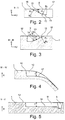
- Fig.2
- das Laufstreifenprofil von
Fig.1 in Schnittdarstellung gemäß Schnitt II-II, - Fig.3
- das Laufstreifenprofil von
Fig.1 in Schnittdarstellung gemäß Schnitt III-III, - Fig.4
- das Laufstreifenprofil von
Fig.1 in Schnittdarstellung gemäß Schnitt IV-IV, - Fig.5
- das Laufstreifenprofil von
Fig.1 in Schnittdarstellung gemäß Schnitt V-V, - Fig.6
- eine Draufsicht auf einen Abschnitt eines symmetrischen Laufstreifenprofiles eines PKW-Fahrzeugluftreifens.
- Die
Figuren 1 bis 5 zeigen ein Laufstreifenprofil eines Fahrzeugluftreifens für PKW-Fahrzeuge mit einer seitengebundenen, asymmetrischen Laufstreifenprofilierung mit einer in axialer Richtung A des Fahrzeugluftreifens für den Einsatz am Fahrzeug zur Fahrzeugaußenseite OU hin und mit einer zur Fahrzeuginnenseite IN ausgebildeten Seite. Das Laufstreifenprofil ist an seiner zur Fahrzeugaußenseite OU hin weisend ausgebildeten Reifenschulter mit einer über den Umfang des Fahrzeuglufreifens erstreckt ausgebildeten Profilrippe 1 ausgebildet, welche sich in Umfangsrichtung U des Fahrzeugluftreifens ausgerichtet über den gesamten Umfang des Fahrzeuglufreifens erstreckt. In axialer Richtung A zu der zur Fahrzeuginnenseite IN hin ausgebildeten Schulter ist benachbart zur Profilrippe 1 eine Profilblockreihe 2 bekannter Art ausgebildet, welche sich über den gesamten Umfang des Fahrzeugluftreifens erstreckt und in Umfangsrichtung U ausgerichtet ist. Die Profilblockreihe 2 ist in bekannter Weise aus in Umfangsrichtung U hintereinander angeordneten und jeweils durch Querrillen voneinander getrennten Profilblockelementen ausgebildet. In axialer Richtung A zu der zur Fahrzeuginnenseite IN hin ausgebildeten Schulter ist benachbart zur Profilblockreihe 2 eine Profilblockreihe 3 bekannter Art ausgebildet, welche sich über den gesamten Umfang des Fahrzeugluftreifens erstreckt und in Umfangsrichtung U ausgerichtet ist. Die Profilblockreihe 3 ist in bekannter Weise aus in Umfangsrichtung U hintereinander angeordneten und jeweils durch Querrillen voneinander getrennten Profilblockelementen ausgebildet. An der zur Fahrzeuginnenseite IN hin ausgebildeten Reifenschulter ist in axialer Richtung A benachbart zur Profilblockreihe 3 eine Profilblockreihe 4 bekannter Art ausgebildet, welche sich über den gesamten Umfang des Fahrzeugluftreifens erstreckt und in Umfangsrichtung U ausgerichtet ist. Die Profilblockreihe 4 ist in bekannter Weise aus in Umfangsrichtung U hintereinander angeordneten und jeweils durch Querrillen voneinander getrennten Profilblockelementen ausgebildet. - Die Profilrippe 1 und die Profilblockreihe 2 sind in bekannter Weise in axialer Richtung A durch eine in Umfangsrichtung U ausgerichtete und über den gesamten Umfang des Fahrzeugluftreifens erstreckte Umfangsrille 5 voneinander beabstandet. Die Profilblockreihe 2 und die Profilblockreihe 3 sind in axialer Richtung A in bekannter Weise durch eine in Umfangsrichtung U ausgerichtete und über den gesamten Umfang des Fahrzeugluftreifens erstreckte Umfangsrille 6 voneinander beabstandet. Die Profilblockreihe 3 und die Profilblockreihe 4 sind in axialer Richtung A durch eine über den gesamten Umfang des Fahrzeugluftreifens erstreckte und in Umfangsrichtung U ausgerichtete Umfangsrille 7 voneinander beabstandet.
- Die Querrillen der Profilblockreihe 4 erstrecken sich ausgehend von einer Position außerhalb der Bodenabstandsbreite TA. durch die Profilblockreihe 4 bis in die Umfangsrille 7. Die Querrillen der Profilblockreihe 3 erstrecken sich in axialer Richtung A ausgehend von der Umfangsrille 7 bis in die Umfangsrille 6. Die Querrillen der Profilblockreihe 2 erstrecken sich in axialer Richtung A ausgehend von der Umfangsrille 6 bis in die Umfangsrille 5.
- Die Profilrippe 1 ist in ihrer in axialer Richtung A ausgehend von der Umfangsrille 5 zur Reifenaußenseite OU hin im axialen Erstreckungsbereich der Bodenaufstandsbreite TA gemessenen Breite größer ausgebildet als die Breite der Profilblockreihen 2, 3 und 4.
- In der Profilrippe 1 sind über den Umfang des Fahrzeugluftreifens verteilt Umfangssegmenten 25 ausgebildet, in denen jeweils ein Paar von in axialer Richtung A mit Abstand c voneinander beabstandeten Rillen 8 und 9 ausgebildet sind, die sich in Umfangsrichtung U des Fahrzeugluftreifens erstrecken. Die Rillen 8 und 9 erstrecken sich dabei jeweils ausgehend von einem Rillenanfang 16 im Umfangssegment 25 in Umfangsrichtung U mit einer in Umfangsrichtung gemessenen Längenerstreckung L und enden in einer Schrägrille 10 bzw. 11. Dabei endet dabei eine Rille 8 jeweils in einer Schrägrille 10. Eine Rille 9 endet jeweils in einer Schrägrille 11. Die Rillen 8 und 9 sind dabei längs ihrer Längenerstreckung L mit einer in axialer Richtung A gemessenen Breite B ausgebildet, wobei die Breite B jeweils in der die Rippe in radialer Richtung R des Fahrzeugluftreifens nach außen hin begrenzenden, die Straßenkontaktoberfläche bildenden, radial äußeren Oberfläche 12 der Profilrippe 1 gemessen wird.
- Im dargestellten Ausführungsbeispiel sind die Rillen 8 und 9 über ihre gesamte in radialer Richtung R gemessene radiale Erstreckung ausgehend von dem die jeweilige Rille 8 bzw. 9 nach radial innen begrenzenden Rillengrund 13 bis zur radial äußeren Oberfläche 12 der Profilrippe 1 längs ihrer gesamten Längenerstreckung der Länge L mit der Breite B ausgebildet.
- Ausgehend von ihrem Rillenanfang 16 bis zur Schrägrille 10 ist die Erstreckungsrichtung der Rille 8 in entgegengesetzter Umfangsrichtung zu der vom Rillenanfang 16 der Rille 9 zur Schrägrille 11 hin gerichteten Erstreckungsrichtung der Rille 9 orientiert.
- Die Schrägrille 10 erstreckt sich von der Rille 8 geradlinig ausgehend mit einer axialen Richtungskomponente A in einer von den beiden Rillen 8 und 9 wegweisenden Richtung zur Reifenaußenseite OU hin bis in eine Position außerhalb der Bodenaufstandsbreite TA und schließt dabei in Orientierungsrichtung der Rille 8 ausgehend vom Beginn 16 der Rille 8 zur Schrägrille 10 hin gesehen (d.h. in
Figur 1 von oben nach unten gesehen), einen Winkel β zur Umfangsrichtung U ein. Die Schrägrille 11 erstreckt sich ausgehend von der Rille 9 geradlinig bis in die Umfangsrille 5 und schließt dabei in der Orientierungsrichtung der Rille 9 ausgehend vom Rillenbeginn 16 der Rille 9 zur Schrägrille 11 hin gesehen (d.h. inFigur 1 von unten nach oben gesehen) einen Windel α zur Umfangsrichtung U des Fahrzeugluftreifens ein. - Der Winkel α ist zwischen 40° und 90° gewählt. Im dargestellten Ausführungsbeispiel ist α = 45° gewählt. Der Winkel β ist zwischen 40° und 90° gewählt. Im dargestellten Ausführungsbeispiel ist β = 80° gewählt. Die gewählten Winkel β und α bedeuten auch, dass im dargestellten Ausführungsbeispiel in axialer Richtung A ausgehend von der Reifenaußenseite OU zur Reifeninnenseite IN innerhalb der Bodenaufstandsbreite TA. die Schrägrillen 10 und 11 längs ihrer axialen Erstreckung eine Neigung mit gleicher Neigungsrichtung aufweisen.
- Wie in
Figur 2 zu erkennen ist, ist die Rille 8, ausgehend vom Beginn 16 der Rille 8 über ihre Erstreckungslänge L in Umfangsrichtung U bis zur Einmündung in die Schrägrille 10 zunächst in einem ersten Erstreckungsbereich 15 mit einer progressiv zunehmenden Rillentiefe T und in einem sich an den ersten Erstreckungsbereich 15 anschließenden zweiten Erstreckungsbereich 14 mit einer degressiv zunehmenden Rillentiefe T ausgebildet ist. Der zweite Erstreckungsbereich 14 erstreckt sich bis zur Einmündung der Rille 8 in die Schrägrille 10. - Die Rillentiefe T der Rille 9 ist - wie dargestellt in
Figur 3 - ausgehend vom Beginn 16 der Rille 9 über ihre Erstreckungslänge L in Umfangsrichtung U bis zur Einmündung in die Schrägrille 11 der Rille 9 längs ihrer gesamten Erstreckung zunächst in einem ersten Erstreckungsbereich 15 mit progressiv zunehmender Rillentiefe T und in einem sich an den ersten Erstreckungsbereich 15 anschließenden zweiten Erstreckungsbereich 14 mit degressiv zunehmender Rillentiefe T ausgebildet. Der zweite Erstreckungsbereich 14 erstreckt sich bis zur Einmündung der Rille 9 in die Schrägrille 11. - Aus diese Weise ist ausgehend vom Rillenbeginn 16, in welcher die Rillentiefe T = 0mm beträgt, bis zur Einmündung in die jeweilige Schrägrille 10 bzw. 11, die jeweilige Rille 8 bzw. 9 über ihren gesamten Erstreckungsbereich mit stetig zunehmender Rillentiefe T ausgebildet und erreicht ihr Maximum TMAX in der Einmündung in die jeweilige Schrägrille 10 bzw. 11. Die Schrägrille 10 ist im Erstreckungsbereich der Einmündung der Rille 8 ebenfalls mit der maximalen Rillentiefe TMAX der Rille 8 ausgebildet. Die Schrägrille 11 ist im Erstreckungsbereich der Einmündung der Rille 9 ebenfalls mit der maximalen Rillentiefe TMAX der Rille 9 ausgebildet. Die Rillentiefe T ist dabei jeweils die radiale Erstreckung der jeweiligen Rille 8 bzw. 9 bzw. 10 bzw. 11 ausgehend von der radial äußeren Oberfläche 12 bis zum jeweiligen die Rille 8 bzw. 9 bzw. 10 bzw. 11 nach radial innen begrenzenden Rillengrund 13 bzw. 17 bzw. 18.
- In den Querschnittsebenen senkrecht zur Reifenachse ist der Rillengrundes 13 der Rille 8 ausgehend vom Beginn 16 der Rille 8 mit einer im ersten Erstreckungsbereich 15 um einen auf der zur Reifeninnenseite des Rillengrundes 13 angeordneten Krümmungsmittelpunkt M2 mit Krümmungsradius R2 gekrümmten und im zweiten Erstreckungsbereich 14 um einen auf der in radialer Richtung zur Reifenaußenseite vom Rillengrund 13 angeordneten Krümmungsmittelpunkt M1 mit Krümmungsradius R1 gekrümmten Konturlinie ausgebildet, wobei der Übergang zwischen der Krümmung im ersten Erstreckungsbereich 15 und der Krümmung im zweiten Erstreckungsbereich 14 tangential ausgebildet ist
- In den Querschnittsebenen senkrecht zur Reifenachse ist der Rillengrundes 13 der Rille 9 ausgehend vom Beginn 16 der Rille 9 mit einer im ersten Erstreckungsbereich 15 um einen auf der zur Reifeninnenseite des Rillengrundes 13 angeordneten Krümmungsmittelpunkt M2 mit Krümmungsradius R2 gekrümmten und im zweiten Erstreckungsbereich 14 um einen auf der in radialer Richtung zur Reifenaußenseite vom Rillengrund 13 angeordneten Krümmungsmittelpunkt M1 mit Krümmungsradius R1 gekrümmten Konturlinie ausgebildet, wobei der Übergang zwischen der Krümmung im ersten Erstreckungsbereich 15 und der Krümmung im zweiten Erstreckungsbereich 14 tangential ausgebildet ist.
- In Umfangsrichtung U des Fahrzeugluftreifens ist der in Umfangsrichtung U gemessene Abstand zwischen dem Beginn 16 einer Rille 8 und der nächstliegenden Schrägrille 10 mit a bezeichnet, ebenso ist der in Umfangsrichtung U gemessene Abstand des Rillenbeginns 16 einer Rille 9 zur nächstliegenden Schrägrille 11 mit a bezeichnet. Somit ergibt sich jeweils zwischen einer ersten Rille 8 und einer in die nächste Rille 8 mündenden angrenzender Schrägrille 10 ein rillenfreier Umfangserstreckungsbereich 26. Ebenso ergibt sich jeweils zwischen einer Rille 9 und einer in die nächste Rille 9 einmündende Schrägrille 11 ein rillenfreier Umfangserstreckungsbereich 26.
- In jedem Umfangssegment 25 sind die beiden Rillen 8 und 9 des in dem Umfangsegment 25 ausgebildeten Paares von Rillen 8 und 9 jeweils mit ihrer von ihrem Rillenbeginn 16 bis zur Einmündung in die jeweilige Schrägrille 10 bzw. 11 gemessenen Umfangserstreckung in einem gemeinsamen, gleichen Umfangserstreckungsabschnitt ausgebildet.
- Die Erstreckungslängen L der Rillen 8 und 9 sind in Abhängigkeit von den gewählten Pitchlängen des Laufstreifenprofiles mit 15mm ≤ L ≤ 50mm ausgebildet. Im dargestellten Ausführungsbeispiel sind die Erstreckungslängen L mit 15mm ≤ L ≤ 20mm - beispielsweise mit L=18mm - ausgebildet. Die Rillen 8 und 9 sind dabei mit ihrer Umfangserstreckung wenigstens zur Hälfte ihrer jeweiligen Erstreckungslänge L im gemeinsamen, gleichen Umfangserstreckungsabschnitt ausgebildet, sodass sie mit einer Umfangsüberlappungslänge von wenigstens der Hälfte ihrer Erstreckungslänge L ausgebildet sind. Die Überlappungslänge ist im dargestellten Ausführungsbeispiel mit wenigstens 10mm ausgebildet.
- In einem nicht dargestellten Ausführungsbeispiel sind die Rillen 8 und 9 mit vollständiger Umfangsüberlappung ausgebildet, dass heißt, dass sie mit gleicher Erstreckungslänge L mit gleicher Umfangspositionierung im Fahrzeugluftreifen und mit identischem Umfangserstreckungsbereich ausgebildet sind.
- Die Ausbildung des Abstand a der Rillen 8 bzw. 9 ist jeweils abhängig vom gewählten Winkel α bzw. β der jeweiligen Schrägrillen 10 und 11. Der Abstand a ist mit 5mm≤a≤20mm gewählt.
- Der in axialer Richtung A gemessene Abstand c zwischen den Rillen 8 und 9 ist mit 3mm ≤ c ≤ 10mm - beispielsweise mit c = 5mm - ausgebildet.
- Die Breite B1 der Schrägrillen 10 und 11 ist mit 1mm≤ B1≤6mm ausgebildet. Die Schrägrille 10 ist dabei bspw. mit einer Breite von B1=2mm, die Schrägrille 11 mit einer Breite B1=3mm ausgebildet.
- Die Rillen 8 und 9 sind mit einer Breite B mit 2mm≤B≤15mm ausgebildet. Die Breite B ist beispielsweise mit B=5mm gewählt.
- Die Rillentiefe T der Rillen 8 und 9 ist in ihrem maximalem Wert TMAX im Bereich der Einmündung in die jeweilige Schrägrille 10 bzw. 11 mit 4mm≤ TMAX ≤ 9mm ausgebildet.
-
Figur 6 zeigt ein alternatives Ausführungsbeispiel eines Laufstreifenprofils mit symmetrischem Profil, bei dem in den beiden Reifenschultern jeweils eine in Umfangsrichtung U des Reifens erstreckte und über den gesamten Umfang ausgerichtete Profilblockreihe 20 bzw. 21 ausgebildet ist. Die Profilblockreihen 20 und 21 sind jeweils aus in Umfangsrichtung U hintereinander angeordneten und durch Querrillen voneinander beabstandeten Profilblockelementen ausgebildet. In axialer Richtung A zwischen den beiden Schulterprofilblockreihen 20 und 21 ist eine Profilrippe 22 ausgebildet, die sich über den gesamten Umfang des Fahrzeugluftreifens erstreckt und in Umfangsrichtung U ausgerichtet ist. Die Profilrippe 22 ist von der Schulterprofilblockreihe 20 durch eine Umfangsrille 23 und von der Schulterprofilblockreihe 21 durch eine Umfangsrille 24 in axialer Richtung A beabstandet. Die Umfangsrillen 23 und 24 erstrecken sich über den gesamten Umfang des Fahrzeugluftreifens und sind in Umfangsrichtung U ausgerichtet. Die Profilrippe 22 ist analog zur Profilrippe 1 vonFigur 1 mit über den Umfang verteilten Umfangssegmenten 25 ausgebildet, in welchen jeweils ein Paar von Rillen 8 und 9 mit Schrägrillen 10 und 11 ausgebildet sind, die den Paaren von Rillen 8 und 9 und Schrägrillen 10 und 11 der Profilrippe 1 vonFigur 1 entsprechend ausgebildet sind. Die Schrägrillen 10 erstrecken sich dabei jeweils ausgehend von einer Rille 8 bis in die Umfangsrille 23, die Schrägrillen 11 erstrecken sich jeweils ausgehend von einer Rille 9 bis in die Umfangsrille 24. Der Winkel β der Schrägrillen 10 ist in dem inFigur 6 dargestellten Ausführungsbeispiel mit 45° ausgebildet. Ebenso ist der Winkel α der - Schrägrille 11 mit β=α=45° dargestellt. Die sonstige Ausbildung der Rillen 8 und 9 mit Tiefenverlauf und Längserstreckung entspricht den in den
Figuren 1 bis 5 dargestellten und/oder erläuterten Ausbildungen. -
- 1
- Profilrippe
- 2
- Profilblockreihe
- 3
- Profilblockreihe
- 4
- Profilblockreihe
- 5
- Umfangsrille
- 6
- Umfangsrille
- 7
- Umfangsrille
- 8
- Rille
- 9
- Rille
- 10
- Schrägrille
- 11
- Schrägrille
- 12
- Radial äußere Oberfläche
- 13
- Rillengrund
- 14
- Zweiter Erstreckungsbereich
- 15
- Erster Erstreckungsbereich
- 16
- Rillenbeginn (Anfang der Rille)
- 17
- Rillengrund
- 18
- Rillengrund
- 19
- 20
- Profilblockreihe
- 21
- Profilblockreihe
- 22
- Profilrippe
- 23
- Umfangsrille
- 24
- Umfangsrille
- 25
- Umfangssegment
- 26
- Umfangssegment
Claims (11)
- Fahrzeugluftreifen mit Laufstreifenprofil mit über den Umfang des Fahrzeugluftreifens erstreckten Profilbändern (1,2,3,4,20,21,22) - wie zum Beispiel Profilrippen oder Profilblockreihen-, die in axialer Richtung A des Fahrzeugluftreifens durch über den Umfang des Fahrzeugluftreifens erstreckte Umfangsrillen (5,6,7,23,24) begrenzt sind, mit wenigstens einer über den Umfang des Fahrzeugluftreifens erstreckten Profilrippe (1,22), in welcher Rillen (8, 9) ausgebildet sind, die in der Profilrippe (1,22) enden,
dadurch gekennzeichnet,
dass in der Profilrippe (1,22) mehrere über den Umfang des Fahrzeugluftreifens verteilt angeordnete und voneinander beabstandete Paare von axial nebeneinander angeordneten, in Umfangsrichtung U ausgerichteten Rillen (8,9) ausgebildet sind, die sich in entgegengesetzter Umfangserstreckungsrichtung jeweils ausgehend von einem Rillenbeginn (16) unter stetiger Zunahme ihrer Rillentiefe T über ein Umfangssegment des Fahrzeugluftreifens mit einem gemeinsamen Umfangserstreckungsabschnitt erstrecken und enden, und
dass die beiden Rillen (8,9) jeweils an ihrem Erstreckungsende in eine quer- oder schrägverlaufende Querrille (10,11) münden. - Fahrzeugluftreifen gemäß den Merkmalen von Anspruch 1,
wobei die Querrille (10,11) jeweils ausgehend von der Rille (8,9) nur zu einer in axialer Richtung A des Reifens gerichteten Seite in der Profilrippe (1,22) ausgebildet ist. - Fahrzeugluftreifen gemäß den Merkmalen von Anspruch 1 oder 2,
wobei die Querrille (10,11) auf einer in axialer Richtung A des Reifens gerichteten Seite der Rille (8,9) jeweils ausgehend von der Rille (8,9) über den gesamten auf dieser Seite der Rille innerhalb der Bodenaufstandsbreite TA des Reifens ausgebildeten axialen Erstreckungsbereich der Profilrippe (1,22) erstreckt ausgebildet ist. - Fahrzeugluftreifen gemäß den Merkmalen von Anspruch 2 oder 3,
wobei die Querrillen (10,11) des Paares von Rillen (8,9) jeweils ausgehend von ihrer zugeordneten Rille (8,9) in zueinander entgegengesetzter axialer Richtung A erstreckt ausgebildet sind. - Fahrzeugluftreifen gemäß den Merkmalen von Anspruch 4,
wobei die beiden Querrillen (10,11) in ihrem gesamten Erstreckungsverlauf ausgehend von ihrer zugeordneten Rille (8,9) mit jeweils von beiden Rillen (8,9) wegweisender axialer Erstreckungsrichtung ausgebildet sind. - Fahrzeugluftreifen gemäß den Merkmalen von einem oder mehreren der vorangegangenen Ansprüche,
wobei wenigstens eine (11) der beiden Querrillen (10,11) in eine die Profilrippe (1,22) in axialer Richtung A begrenzende Umfangsrille (5,24) mündet. - Fahrzeugluftreifen gemäß den Merkmalen von einem oder mehreren der vorangegangenen Ansprüche,
wobei die beiden Rillen (8,9) sich ausgehend von dem Rillenbeginn (16) über ein gemeinsames Umfangssegment des Fahrzeugluftreifens erstrecken und dort enden. - Fahrzeugluftreifen gemäß den Merkmalen von einem oder mehreren der vorangegangenen Ansprüche,
wobei die Rillentiefe T der Rillen (8,9) längs ihrer Erstreckung in Umfangsrichtung kontinuierlich zunimmt. - Fahrzeugluftreifen gemäß den Merkmalen von Anspruch 8,
wobei die Rillentiefe T längs ihrer Erstreckung in Umfangsrichtung U ausgehend vom Rillenbeginn (16) in einem ersten Erstreckungsabschnitt (15) progressiv steigend und in einem zweiten Erstreckungsabschnitt (14) bis zum Rillenende degressiv steigend zunimmt. - Fahrzeugluftreifen gemäß den Merkmalen von einem oder mehreren der vorangegangenen Ansprüche,
wobei die Rippe (1) als Schulterprofilband des Laufstreifens in der für den Einsatz am Fahrzeug als die Außenschulter OU ausgebildeten Reifenschulter ausgebildet ist und
wobei das Laufstreifenprofil insbesondere als asymmetrisches Laufstreifenprofil ausgebildet ist. - Fahrzeugluftreifen gemäß den Merkmalen von einem oder mehreren der Ansprüche 1 bis 9,
wobei die Rippe (22) eine zwischen den Reifenschultern ausgebildete Rippe ist und wobei das Laufstreifenprofil insbesondere als symmetrisches Laufstreifenprofil ausgebildet ist.
Applications Claiming Priority (1)
| Application Number | Priority Date | Filing Date | Title |
|---|---|---|---|
| DE201010060778 DE102010060778A1 (de) | 2010-11-24 | 2010-11-24 | Fahrzeugluftreifen |
Publications (2)
| Publication Number | Publication Date |
|---|---|
| EP2457745A1 EP2457745A1 (de) | 2012-05-30 |
| EP2457745B1 true EP2457745B1 (de) | 2016-07-20 |
Family
ID=45607540
Family Applications (1)
| Application Number | Title | Priority Date | Filing Date |
|---|---|---|---|
| EP11181360.6A Active EP2457745B1 (de) | 2010-11-24 | 2011-09-15 | Fahrzeugluftreifen |
Country Status (2)
| Country | Link |
|---|---|
| EP (1) | EP2457745B1 (de) |
| DE (1) | DE102010060778A1 (de) |
Families Citing this family (6)
| Publication number | Priority date | Publication date | Assignee | Title |
|---|---|---|---|---|
| DE102012108384A1 (de) | 2012-09-10 | 2014-03-13 | Continental Reifen Deutschland Gmbh | Fahrzeugluftreifen |
| JP5799043B2 (ja) * | 2013-03-13 | 2015-10-21 | 株式会社ブリヂストン | 空気入りタイヤ |
| DE102016219017A1 (de) | 2016-09-30 | 2018-04-05 | Continental Reifen Deutschland Gmbh | Fahrzeugluftreifen |
| DE102017222342A1 (de) * | 2017-12-11 | 2019-06-13 | Continental Reifen Deutschland Gmbh | Laufstreifenprofil eines Fahrzeugreifens |
| JP7013251B2 (ja) * | 2018-01-17 | 2022-02-15 | Toyo Tire株式会社 | 空気入りタイヤ |
| DE102020216024A1 (de) * | 2020-12-16 | 2022-06-23 | Continental Reifen Deutschland Gmbh | Laufstreifenprofil eines Fahrzeugluftreifens |
Family Cites Families (4)
| Publication number | Priority date | Publication date | Assignee | Title |
|---|---|---|---|---|
| DE3625120A1 (de) * | 1986-07-25 | 1988-01-28 | Audi Ag | Reifenprofil |
| EP2447090B1 (de) * | 2003-05-21 | 2017-07-05 | Bridgestone Corporation | Luftreifen und Verfahren zum Entwerfen eines Profilmusters dafür |
| JP4145346B1 (ja) * | 2007-11-07 | 2008-09-03 | 横浜ゴム株式会社 | 空気入りタイヤ |
| JP4709303B2 (ja) * | 2009-08-07 | 2011-06-22 | 株式会社ブリヂストン | タイヤ |
-
2010
- 2010-11-24 DE DE201010060778 patent/DE102010060778A1/de not_active Withdrawn
-
2011
- 2011-09-15 EP EP11181360.6A patent/EP2457745B1/de active Active
Also Published As
| Publication number | Publication date |
|---|---|
| EP2457745A1 (de) | 2012-05-30 |
| DE102010060778A1 (de) | 2012-05-24 |
Similar Documents
| Publication | Publication Date | Title |
|---|---|---|
| EP3334612B1 (de) | Fahrzeugluftreifen | |
| EP2457745B1 (de) | Fahrzeugluftreifen | |
| EP3019346B1 (de) | Laufstreifenprofil eines fahrzeugluftreifens | |
| EP3300926B1 (de) | Fahrzeugluftreifen | |
| EP2448776B1 (de) | Fahrzeugluftreifen | |
| EP3224059B1 (de) | Fahrzeugluftreifen | |
| EP2595820B1 (de) | Laufstreifenprofil eines fahrzeugluftreifens | |
| EP3475103B1 (de) | Fahrzeugluftreifen | |
| EP2340949B1 (de) | Fahrzeugreifen | |
| EP2455235B1 (de) | Laufstreifenprofil eines Fahrzeugluftreifens | |
| EP2119574B1 (de) | Laufflächenprofil eines Fahrzeugreifens | |
| EP2489526B1 (de) | Laufstreifenprofil eines Fahrzeugluftreifens | |
| EP0773117A1 (de) | Drehrichtungsungebundenes Laufstreifenprofil eines Fahrzeugreifens mit Blockprofilstruktur | |
| WO2014048635A1 (de) | Fahrzeugluftreifen | |
| EP3538383B1 (de) | Fahrzeugluftreifen | |
| WO2018086777A1 (de) | Fahrzeugluftreifen | |
| EP3300925B1 (de) | Fahrzeugluftreifen | |
| EP2914448B1 (de) | Fahrzeugluftreifen | |
| DE102012101760A1 (de) | Fahrzeugluftreifen | |
| EP3686034B1 (de) | Fahrzeugluftreifen | |
| EP2794298B1 (de) | Laufstreifenprofil eines fahrzeugliftreifens | |
| EP3890994A1 (de) | Laufstreifenprofil eines fahrzeugreifens | |
| EP3224062B1 (de) | Fahrzeugluftreifen | |
| EP1535759B1 (de) | Fahrzeugluftreifen | |
| EP4360913B1 (de) | Fahrzeugluftreifen |
Legal Events
| Date | Code | Title | Description |
|---|---|---|---|
| PUAI | Public reference made under article 153(3) epc to a published international application that has entered the european phase |
Free format text: ORIGINAL CODE: 0009012 |
|
| AK | Designated contracting states |
Kind code of ref document: A1 Designated state(s): AL AT BE BG CH CY CZ DE DK EE ES FI FR GB GR HR HU IE IS IT LI LT LU LV MC MK MT NL NO PL PT RO RS SE SI SK SM TR |
|
| AX | Request for extension of the european patent |
Extension state: BA ME |
|
| 17P | Request for examination filed |
Effective date: 20121130 |
|
| GRAP | Despatch of communication of intention to grant a patent |
Free format text: ORIGINAL CODE: EPIDOSNIGR1 |
|
| INTG | Intention to grant announced |
Effective date: 20160407 |
|
| GRAS | Grant fee paid |
Free format text: ORIGINAL CODE: EPIDOSNIGR3 |
|
| GRAA | (expected) grant |
Free format text: ORIGINAL CODE: 0009210 |
|
| AK | Designated contracting states |
Kind code of ref document: B1 Designated state(s): AL AT BE BG CH CY CZ DE DK EE ES FI FR GB GR HR HU IE IS IT LI LT LU LV MC MK MT NL NO PL PT RO RS SE SI SK SM TR |
|
| REG | Reference to a national code |
Ref country code: GB Ref legal event code: FG4D Free format text: NOT ENGLISH |
|
| REG | Reference to a national code |
Ref country code: CH Ref legal event code: EP |
|
| REG | Reference to a national code |
Ref country code: IE Ref legal event code: FG4D Free format text: LANGUAGE OF EP DOCUMENT: GERMAN |
|
| REG | Reference to a national code |
Ref country code: AT Ref legal event code: REF Ref document number: 813738 Country of ref document: AT Kind code of ref document: T Effective date: 20160815 |
|
| REG | Reference to a national code |
Ref country code: DE Ref legal event code: R096 Ref document number: 502011010193 Country of ref document: DE |
|
| REG | Reference to a national code |
Ref country code: FR Ref legal event code: PLFP Year of fee payment: 6 |
|
| REG | Reference to a national code |
Ref country code: LT Ref legal event code: MG4D |
|
| REG | Reference to a national code |
Ref country code: NL Ref legal event code: MP Effective date: 20160720 |
|
| PG25 | Lapsed in a contracting state [announced via postgrant information from national office to epo] |
Ref country code: NO Free format text: LAPSE BECAUSE OF FAILURE TO SUBMIT A TRANSLATION OF THE DESCRIPTION OR TO PAY THE FEE WITHIN THE PRESCRIBED TIME-LIMIT Effective date: 20161020 Ref country code: LT Free format text: LAPSE BECAUSE OF FAILURE TO SUBMIT A TRANSLATION OF THE DESCRIPTION OR TO PAY THE FEE WITHIN THE PRESCRIBED TIME-LIMIT Effective date: 20160720 Ref country code: IS Free format text: LAPSE BECAUSE OF FAILURE TO SUBMIT A TRANSLATION OF THE DESCRIPTION OR TO PAY THE FEE WITHIN THE PRESCRIBED TIME-LIMIT Effective date: 20161120 Ref country code: IT Free format text: LAPSE BECAUSE OF FAILURE TO SUBMIT A TRANSLATION OF THE DESCRIPTION OR TO PAY THE FEE WITHIN THE PRESCRIBED TIME-LIMIT Effective date: 20160720 Ref country code: NL Free format text: LAPSE BECAUSE OF FAILURE TO SUBMIT A TRANSLATION OF THE DESCRIPTION OR TO PAY THE FEE WITHIN THE PRESCRIBED TIME-LIMIT Effective date: 20160720 Ref country code: HR Free format text: LAPSE BECAUSE OF FAILURE TO SUBMIT A TRANSLATION OF THE DESCRIPTION OR TO PAY THE FEE WITHIN THE PRESCRIBED TIME-LIMIT Effective date: 20160720 Ref country code: RS Free format text: LAPSE BECAUSE OF FAILURE TO SUBMIT A TRANSLATION OF THE DESCRIPTION OR TO PAY THE FEE WITHIN THE PRESCRIBED TIME-LIMIT Effective date: 20160720 Ref country code: FI Free format text: LAPSE BECAUSE OF FAILURE TO SUBMIT A TRANSLATION OF THE DESCRIPTION OR TO PAY THE FEE WITHIN THE PRESCRIBED TIME-LIMIT Effective date: 20160720 |
|
| PG25 | Lapsed in a contracting state [announced via postgrant information from national office to epo] |
Ref country code: PT Free format text: LAPSE BECAUSE OF FAILURE TO SUBMIT A TRANSLATION OF THE DESCRIPTION OR TO PAY THE FEE WITHIN THE PRESCRIBED TIME-LIMIT Effective date: 20161121 Ref country code: PL Free format text: LAPSE BECAUSE OF FAILURE TO SUBMIT A TRANSLATION OF THE DESCRIPTION OR TO PAY THE FEE WITHIN THE PRESCRIBED TIME-LIMIT Effective date: 20160720 Ref country code: GR Free format text: LAPSE BECAUSE OF FAILURE TO SUBMIT A TRANSLATION OF THE DESCRIPTION OR TO PAY THE FEE WITHIN THE PRESCRIBED TIME-LIMIT Effective date: 20161021 Ref country code: BE Free format text: LAPSE BECAUSE OF NON-PAYMENT OF DUE FEES Effective date: 20160930 Ref country code: LV Free format text: LAPSE BECAUSE OF FAILURE TO SUBMIT A TRANSLATION OF THE DESCRIPTION OR TO PAY THE FEE WITHIN THE PRESCRIBED TIME-LIMIT Effective date: 20160720 Ref country code: SE Free format text: LAPSE BECAUSE OF FAILURE TO SUBMIT A TRANSLATION OF THE DESCRIPTION OR TO PAY THE FEE WITHIN THE PRESCRIBED TIME-LIMIT Effective date: 20160720 Ref country code: ES Free format text: LAPSE BECAUSE OF FAILURE TO SUBMIT A TRANSLATION OF THE DESCRIPTION OR TO PAY THE FEE WITHIN THE PRESCRIBED TIME-LIMIT Effective date: 20160720 |
|
| REG | Reference to a national code |
Ref country code: DE Ref legal event code: R097 Ref document number: 502011010193 Country of ref document: DE |
|
| PG25 | Lapsed in a contracting state [announced via postgrant information from national office to epo] |
Ref country code: MC Free format text: LAPSE BECAUSE OF FAILURE TO SUBMIT A TRANSLATION OF THE DESCRIPTION OR TO PAY THE FEE WITHIN THE PRESCRIBED TIME-LIMIT Effective date: 20160720 Ref country code: EE Free format text: LAPSE BECAUSE OF FAILURE TO SUBMIT A TRANSLATION OF THE DESCRIPTION OR TO PAY THE FEE WITHIN THE PRESCRIBED TIME-LIMIT Effective date: 20160720 Ref country code: RO Free format text: LAPSE BECAUSE OF FAILURE TO SUBMIT A TRANSLATION OF THE DESCRIPTION OR TO PAY THE FEE WITHIN THE PRESCRIBED TIME-LIMIT Effective date: 20160720 |
|
| REG | Reference to a national code |
Ref country code: CH Ref legal event code: PL |
|
| PLBE | No opposition filed within time limit |
Free format text: ORIGINAL CODE: 0009261 |
|
| STAA | Information on the status of an ep patent application or granted ep patent |
Free format text: STATUS: NO OPPOSITION FILED WITHIN TIME LIMIT |
|
| PG25 | Lapsed in a contracting state [announced via postgrant information from national office to epo] |
Ref country code: SK Free format text: LAPSE BECAUSE OF FAILURE TO SUBMIT A TRANSLATION OF THE DESCRIPTION OR TO PAY THE FEE WITHIN THE PRESCRIBED TIME-LIMIT Effective date: 20160720 Ref country code: CZ Free format text: LAPSE BECAUSE OF FAILURE TO SUBMIT A TRANSLATION OF THE DESCRIPTION OR TO PAY THE FEE WITHIN THE PRESCRIBED TIME-LIMIT Effective date: 20160720 Ref country code: SM Free format text: LAPSE BECAUSE OF FAILURE TO SUBMIT A TRANSLATION OF THE DESCRIPTION OR TO PAY THE FEE WITHIN THE PRESCRIBED TIME-LIMIT Effective date: 20160720 Ref country code: DK Free format text: LAPSE BECAUSE OF FAILURE TO SUBMIT A TRANSLATION OF THE DESCRIPTION OR TO PAY THE FEE WITHIN THE PRESCRIBED TIME-LIMIT Effective date: 20160720 Ref country code: BG Free format text: LAPSE BECAUSE OF FAILURE TO SUBMIT A TRANSLATION OF THE DESCRIPTION OR TO PAY THE FEE WITHIN THE PRESCRIBED TIME-LIMIT Effective date: 20161020 |
|
| 26N | No opposition filed |
Effective date: 20170421 |
|
| REG | Reference to a national code |
Ref country code: IE Ref legal event code: MM4A |
|
| PG25 | Lapsed in a contracting state [announced via postgrant information from national office to epo] |
Ref country code: LI Free format text: LAPSE BECAUSE OF NON-PAYMENT OF DUE FEES Effective date: 20160930 Ref country code: CH Free format text: LAPSE BECAUSE OF NON-PAYMENT OF DUE FEES Effective date: 20160930 Ref country code: IE Free format text: LAPSE BECAUSE OF NON-PAYMENT OF DUE FEES Effective date: 20160915 |
|
| PG25 | Lapsed in a contracting state [announced via postgrant information from national office to epo] |
Ref country code: LU Free format text: LAPSE BECAUSE OF NON-PAYMENT OF DUE FEES Effective date: 20160915 Ref country code: SI Free format text: LAPSE BECAUSE OF FAILURE TO SUBMIT A TRANSLATION OF THE DESCRIPTION OR TO PAY THE FEE WITHIN THE PRESCRIBED TIME-LIMIT Effective date: 20160720 |
|
| REG | Reference to a national code |
Ref country code: FR Ref legal event code: PLFP Year of fee payment: 7 |
|
| REG | Reference to a national code |
Ref country code: AT Ref legal event code: MM01 Ref document number: 813738 Country of ref document: AT Kind code of ref document: T Effective date: 20160915 |
|
| REG | Reference to a national code |
Ref country code: BE Ref legal event code: MM Effective date: 20160930 |
|
| PG25 | Lapsed in a contracting state [announced via postgrant information from national office to epo] |
Ref country code: AT Free format text: LAPSE BECAUSE OF NON-PAYMENT OF DUE FEES Effective date: 20160915 |
|
| PG25 | Lapsed in a contracting state [announced via postgrant information from national office to epo] |
Ref country code: CY Free format text: LAPSE BECAUSE OF FAILURE TO SUBMIT A TRANSLATION OF THE DESCRIPTION OR TO PAY THE FEE WITHIN THE PRESCRIBED TIME-LIMIT Effective date: 20160720 Ref country code: HU Free format text: LAPSE BECAUSE OF FAILURE TO SUBMIT A TRANSLATION OF THE DESCRIPTION OR TO PAY THE FEE WITHIN THE PRESCRIBED TIME-LIMIT; INVALID AB INITIO Effective date: 20110915 |
|
| PG25 | Lapsed in a contracting state [announced via postgrant information from national office to epo] |
Ref country code: MK Free format text: LAPSE BECAUSE OF FAILURE TO SUBMIT A TRANSLATION OF THE DESCRIPTION OR TO PAY THE FEE WITHIN THE PRESCRIBED TIME-LIMIT Effective date: 20160720 Ref country code: TR Free format text: LAPSE BECAUSE OF FAILURE TO SUBMIT A TRANSLATION OF THE DESCRIPTION OR TO PAY THE FEE WITHIN THE PRESCRIBED TIME-LIMIT Effective date: 20160720 Ref country code: MT Free format text: LAPSE BECAUSE OF FAILURE TO SUBMIT A TRANSLATION OF THE DESCRIPTION OR TO PAY THE FEE WITHIN THE PRESCRIBED TIME-LIMIT Effective date: 20160720 |
|
| REG | Reference to a national code |
Ref country code: FR Ref legal event code: PLFP Year of fee payment: 8 |
|
| PG25 | Lapsed in a contracting state [announced via postgrant information from national office to epo] |
Ref country code: AL Free format text: LAPSE BECAUSE OF FAILURE TO SUBMIT A TRANSLATION OF THE DESCRIPTION OR TO PAY THE FEE WITHIN THE PRESCRIBED TIME-LIMIT Effective date: 20160720 |
|
| PGFP | Annual fee paid to national office [announced via postgrant information from national office to epo] |
Ref country code: GB Payment date: 20210920 Year of fee payment: 11 |
|
| GBPC | Gb: european patent ceased through non-payment of renewal fee |
Effective date: 20220915 |
|
| PG25 | Lapsed in a contracting state [announced via postgrant information from national office to epo] |
Ref country code: GB Free format text: LAPSE BECAUSE OF NON-PAYMENT OF DUE FEES Effective date: 20220915 |
|
| REG | Reference to a national code |
Ref country code: DE Ref legal event code: R081 Ref document number: 502011010193 Country of ref document: DE Owner name: CONTINENTAL REIFEN DEUTSCHLAND GMBH, DE Free format text: FORMER OWNER: CONTINENTAL REIFEN DEUTSCHLAND GMBH, 30165 HANNOVER, DE |
|
| PGFP | Annual fee paid to national office [announced via postgrant information from national office to epo] |
Ref country code: DE Payment date: 20240930 Year of fee payment: 14 |
|
| PGFP | Annual fee paid to national office [announced via postgrant information from national office to epo] |
Ref country code: FR Payment date: 20250922 Year of fee payment: 15 |