EP2457762B1 - Kraftstoffsystem und fahrzeug - Google Patents
Kraftstoffsystem und fahrzeug Download PDFInfo
- Publication number
- EP2457762B1 EP2457762B1 EP09847551.0A EP09847551A EP2457762B1 EP 2457762 B1 EP2457762 B1 EP 2457762B1 EP 09847551 A EP09847551 A EP 09847551A EP 2457762 B1 EP2457762 B1 EP 2457762B1
- Authority
- EP
- European Patent Office
- Prior art keywords
- fuel
- assembly
- pressure
- filling
- line
- Prior art date
- Legal status (The legal status is an assumption and is not a legal conclusion. Google has not performed a legal analysis and makes no representation as to the accuracy of the status listed.)
- Active
Links
Images



Classifications
-
- H—ELECTRICITY
- H01—ELECTRIC ELEMENTS
- H01M—PROCESSES OR MEANS, e.g. BATTERIES, FOR THE DIRECT CONVERSION OF CHEMICAL ENERGY INTO ELECTRICAL ENERGY
- H01M8/00—Fuel cells; Manufacture thereof
- H01M8/04—Auxiliary arrangements, e.g. for control of pressure or for circulation of fluids
- H01M8/04082—Arrangements for control of reactant parameters, e.g. pressure or concentration
- H01M8/04201—Reactant storage and supply, e.g. means for feeding, pipes
-
- B—PERFORMING OPERATIONS; TRANSPORTING
- B60—VEHICLES IN GENERAL
- B60K—ARRANGEMENT OR MOUNTING OF PROPULSION UNITS OR OF TRANSMISSIONS IN VEHICLES; ARRANGEMENT OR MOUNTING OF PLURAL DIVERSE PRIME-MOVERS IN VEHICLES; AUXILIARY DRIVES FOR VEHICLES; INSTRUMENTATION OR DASHBOARDS FOR VEHICLES; ARRANGEMENTS IN CONNECTION WITH COOLING, AIR INTAKE, GAS EXHAUST OR FUEL SUPPLY OF PROPULSION UNITS IN VEHICLES
- B60K15/00—Arrangement in connection with fuel supply of combustion engines or other fuel consuming energy converters, e.g. fuel cells; Mounting or construction of fuel tanks
- B60K15/01—Arrangement of fuel conduits
- B60K15/013—Arrangement of fuel conduits of gas conduits
-
- H—ELECTRICITY
- H01—ELECTRIC ELEMENTS
- H01M—PROCESSES OR MEANS, e.g. BATTERIES, FOR THE DIRECT CONVERSION OF CHEMICAL ENERGY INTO ELECTRICAL ENERGY
- H01M8/00—Fuel cells; Manufacture thereof
- H01M8/04—Auxiliary arrangements, e.g. for control of pressure or for circulation of fluids
- H01M8/04082—Arrangements for control of reactant parameters, e.g. pressure or concentration
- H01M8/04089—Arrangements for control of reactant parameters, e.g. pressure or concentration of gaseous reactants
-
- H—ELECTRICITY
- H01—ELECTRIC ELEMENTS
- H01M—PROCESSES OR MEANS, e.g. BATTERIES, FOR THE DIRECT CONVERSION OF CHEMICAL ENERGY INTO ELECTRICAL ENERGY
- H01M8/00—Fuel cells; Manufacture thereof
- H01M8/04—Auxiliary arrangements, e.g. for control of pressure or for circulation of fluids
- H01M8/04082—Arrangements for control of reactant parameters, e.g. pressure or concentration
- H01M8/04201—Reactant storage and supply, e.g. means for feeding, pipes
- H01M8/04208—Cartridges, cryogenic media or cryogenic reservoirs
-
- H—ELECTRICITY
- H01—ELECTRIC ELEMENTS
- H01M—PROCESSES OR MEANS, e.g. BATTERIES, FOR THE DIRECT CONVERSION OF CHEMICAL ENERGY INTO ELECTRICAL ENERGY
- H01M8/00—Fuel cells; Manufacture thereof
- H01M8/04—Auxiliary arrangements, e.g. for control of pressure or for circulation of fluids
- H01M8/04298—Processes for controlling fuel cells or fuel cell systems
- H01M8/04313—Processes for controlling fuel cells or fuel cell systems characterised by the detection or assessment of variables; characterised by the detection or assessment of failure or abnormal function
- H01M8/0438—Pressure; Ambient pressure; Flow
-
- H—ELECTRICITY
- H01—ELECTRIC ELEMENTS
- H01M—PROCESSES OR MEANS, e.g. BATTERIES, FOR THE DIRECT CONVERSION OF CHEMICAL ENERGY INTO ELECTRICAL ENERGY
- H01M8/00—Fuel cells; Manufacture thereof
- H01M8/04—Auxiliary arrangements, e.g. for control of pressure or for circulation of fluids
- H01M8/04298—Processes for controlling fuel cells or fuel cell systems
- H01M8/04313—Processes for controlling fuel cells or fuel cell systems characterised by the detection or assessment of variables; characterised by the detection or assessment of failure or abnormal function
- H01M8/0438—Pressure; Ambient pressure; Flow
- H01M8/04388—Pressure; Ambient pressure; Flow of anode reactants at the inlet or inside the fuel cell
-
- B—PERFORMING OPERATIONS; TRANSPORTING
- B60—VEHICLES IN GENERAL
- B60K—ARRANGEMENT OR MOUNTING OF PROPULSION UNITS OR OF TRANSMISSIONS IN VEHICLES; ARRANGEMENT OR MOUNTING OF PLURAL DIVERSE PRIME-MOVERS IN VEHICLES; AUXILIARY DRIVES FOR VEHICLES; INSTRUMENTATION OR DASHBOARDS FOR VEHICLES; ARRANGEMENTS IN CONNECTION WITH COOLING, AIR INTAKE, GAS EXHAUST OR FUEL SUPPLY OF PROPULSION UNITS IN VEHICLES
- B60K15/00—Arrangement in connection with fuel supply of combustion engines or other fuel consuming energy converters, e.g. fuel cells; Mounting or construction of fuel tanks
- B60K15/03—Fuel tanks
- B60K15/03006—Gas tanks
- B60K2015/03019—Filling of gas tanks
-
- B—PERFORMING OPERATIONS; TRANSPORTING
- B60—VEHICLES IN GENERAL
- B60K—ARRANGEMENT OR MOUNTING OF PROPULSION UNITS OR OF TRANSMISSIONS IN VEHICLES; ARRANGEMENT OR MOUNTING OF PLURAL DIVERSE PRIME-MOVERS IN VEHICLES; AUXILIARY DRIVES FOR VEHICLES; INSTRUMENTATION OR DASHBOARDS FOR VEHICLES; ARRANGEMENTS IN CONNECTION WITH COOLING, AIR INTAKE, GAS EXHAUST OR FUEL SUPPLY OF PROPULSION UNITS IN VEHICLES
- B60K15/00—Arrangement in connection with fuel supply of combustion engines or other fuel consuming energy converters, e.g. fuel cells; Mounting or construction of fuel tanks
- B60K15/03—Fuel tanks
- B60K15/03006—Gas tanks
- B60K2015/03026—Gas tanks comprising a valve
-
- B—PERFORMING OPERATIONS; TRANSPORTING
- B60—VEHICLES IN GENERAL
- B60K—ARRANGEMENT OR MOUNTING OF PROPULSION UNITS OR OF TRANSMISSIONS IN VEHICLES; ARRANGEMENT OR MOUNTING OF PLURAL DIVERSE PRIME-MOVERS IN VEHICLES; AUXILIARY DRIVES FOR VEHICLES; INSTRUMENTATION OR DASHBOARDS FOR VEHICLES; ARRANGEMENTS IN CONNECTION WITH COOLING, AIR INTAKE, GAS EXHAUST OR FUEL SUPPLY OF PROPULSION UNITS IN VEHICLES
- B60K15/00—Arrangement in connection with fuel supply of combustion engines or other fuel consuming energy converters, e.g. fuel cells; Mounting or construction of fuel tanks
- B60K15/03—Fuel tanks
- B60K2015/03309—Tanks specially adapted for particular fuels
- B60K2015/03315—Tanks specially adapted for particular fuels for hydrogen
-
- Y—GENERAL TAGGING OF NEW TECHNOLOGICAL DEVELOPMENTS; GENERAL TAGGING OF CROSS-SECTIONAL TECHNOLOGIES SPANNING OVER SEVERAL SECTIONS OF THE IPC; TECHNICAL SUBJECTS COVERED BY FORMER USPC CROSS-REFERENCE ART COLLECTIONS [XRACs] AND DIGESTS
- Y02—TECHNOLOGIES OR APPLICATIONS FOR MITIGATION OR ADAPTATION AGAINST CLIMATE CHANGE
- Y02E—REDUCTION OF GREENHOUSE GAS [GHG] EMISSIONS, RELATED TO ENERGY GENERATION, TRANSMISSION OR DISTRIBUTION
- Y02E60/00—Enabling technologies; Technologies with a potential or indirect contribution to GHG emissions mitigation
- Y02E60/30—Hydrogen technology
- Y02E60/50—Fuel cells
Definitions
- the present invention relates to a fuel system which includes a fuel storage source, a filling line adapted to connect the fuel storage source to a filling port, a supply line adapted to connect the fuel storage source to a fuel destination, and a pressure reducing valve installed in the supply line. Also, the present invention relates to a vehicle equipped with the fuel system.
- Patent Literature 1 a vehicle equipped with a fuel cell system having two hydrogen tanks is known (see Patent Literature 1).
- Each hydrogen tank is connected to a fuel cell via supply lines in which two lines are integrated into one line.
- each of the two hydrogen tanks is connected with a high-pressure pipe assembly, which is connected collectively to a single line of fuel piping, which is then connected to the fuel cell.
- a regulator for reducing hydrogen gas pressure is inserted midway in the fuel piping and is placed between the two hydrogen tanks.
- Patent Literature 1 Japanese Patent Laid-Open No. 2004-161055 (Paragraph 0017, Figure 1 )
- US 2005/202292 A1 discloses a fuel delivery system comprising two fuel containers 1, a filling line with a disconnect valve 5 and a supply line with a disconnect valve 4.
- the supply line further comprises a pressure regulator 2 and two pressure gauges 6 and 7.
- An object of the present invention is to provide a fuel system and a vehicle which can improve mountability and assembly ease of parts.
- the assembly functions as a pipe fitting inserted in the supply line and has a line branch point for the supply line.
- the pressure reducing valve and first pressure sensor are integrated into the assembly, parts commonality can be enhanced and man-hours of piping assembly operations for the supply line can be reduced, compared to when the reducing valve, the first pressure sensor, and the assembly are installed separately. Also, since the integrated assembly can be handled, mountability can be improved, for example, when the fuel system is mounted on a vehicle. Furthermore, the configuration of the pressure reducing valve and the first pressure sensor enables the first pressure sensor to monitor the primary or secondary pressure of the pressure reducing valve.
- the assembly may have a first leakage check port at a branch destination from the supply line.
- This configuration allows the leakage check port to be installed by effectively using the assembly. Also, when a fluid is introduced through the leakage check port, junctions and the like of the supply line in the assembly can be checked for leakage.
- the pressure reducing valve and the first pressure sensor may be integrated into the assembly on a downstream side of the branch point which corresponds to the side of the fuel destination. This provides a configuration suitable for reducing pressure on the downstream side of the branch point.
- At least one of an injector, a second pressure sensor, a relief valve, and a third sensor may be further integrated into the assembly, where the injector is installed on a downstream side of the pressure reducing valve and adapted to inject fuel, the second pressure sensor is adapted to detect primary or secondary pressure of the injector, the relief valve is adapted to communicate between the pressure reducing valve and the injector on a supply line, and the third sensor is adapted to detect pressure in the fuel storage source.
- This configuration allows various parts to be installed by effectively using the assembly, improving assembly ease and mountability.
- the assembly also may function as a pipe fitting inserted in the filling line.
- This configuration eliminates the need to install a separate pipe fitting for the filling line. That is, the assembly functions as a pipe fitting for both the supply line and filling line, further facilitating parts commonality.
- the assembly may have a line branch point for the filling line and have a second leakage check port at a branch destination from the filling line.
- junctions and the like of the filling line in the assembly can also be checked for leakage.
- connections of pipes of the supply line and connections of pipes of the filling line may be provided next to each other. Consequently, the connections for the supply line and the connections for the filling line can be separated from each other in the assembly. This makes it possible to make connections intensively by securing piping spaces for the supply line and filling line appropriately in the assembly.
- connections of pipes of the supply line may be located above the connections of pipes of the filling line in a direction of gravity. This further can improve workability when the pipes on the side of the filling line are assembled below the pipes on the side of the supply line later than the pipes on the side of the supply line.
- a plurality of the fuel storage sources may be provided; and the supply line coming from the fuel destination may be branched in the assembly and connected in parallel to each of the fuel storage sources. This allows the assembly to be used as a manifold which gathers together pipes from the plurality of fuel storage sources.
- the filling line coming from the filling port may be branched in the assembly and connected in parallel to each of the fuel storage sources. This allows the assembly to be similarly used as a manifold which branches the pipe coming from the filling port.
- the fuel storage sources may be high-pressure tanks each of which includes a tank body and a shoulder continuous with an end of the tank body; and the assembly may be placed between adjacent high-pressure tanks and faces the shoulder of at least one of the high-pressure tanks. This can reduce damage to the high-pressure tanks, for example, in case the vehicle carrying the high-pressure tanks comes into collision.
- the fuel destination may be a fuel cell.
- the present invention provides a vehicle equipped with the above-described fuel system according to the present invention.
- the present invention can provide a vehicle with improved assembly ease of pipes in the supply line and improved vehicle-mountability of parts (the pressure reducing valve, first pressure sensor, assembly, and the like) on the supply line.
- FCHVs fuel cell hybrid vehicles
- electric cars electric cars
- hybrid cars hybrid cars
- stationary power supplies e.g., shipping, aircraft, and robots
- movable bodies e.g., shipping, aircraft, and robots
- a fuel cell system 1 includes a fuel cell 2, a fuel gas system 3, and oxidation gas system.
- the fuel gas and oxidation gas are collectively referred to as reactive gases.
- the fuel gas is, for example, hydrogen gas while the oxidation gas is, for example, air.
- the fuel cell 2 is made up of solid polymer electrolyte fuel cells organized into a stacked structure in which a large number of single cells are stacked together.
- Figure 1 schematically shows a structure of the single cell in the fuel cell 2.
- the single cell includes an MEA (membrane electrode assembly) which comprises an electrolyte membrane 10, a fuel electrode 11, and an air electrode 12.
- the electrolyte membrane 10 is an ion-exchange membrane made of fluorocarbon resin, for example.
- the fuel electrode 11 and the air electrode 12 are installed on opposite sides of the electrolyte membrane 10.
- the single cell includes a pair of separators 14 and 15 placed so as to sandwich the fuel electrode 11 and the air electrode 12 from both sides.
- the fuel cell 2 generates electric power by means of electrochemical reactions between the fuel gas supplied to a fuel gas channel 16 of the separator 14 and the oxidation gas supplied to an oxidation gas channel 17 of the separator 15.
- the electric power generated by the fuel cell 2 is supplied to a load 18 such as a traction motor.
- the fuel gas system 3 includes two fuel tanks 21 a and 21 b, a filling line 22 which branches midway, and a supply line 23 which is gathered together midway.
- the fuel tanks 21 a and 21 b may be either high-pressure tanks that store high-pressure hydrogen gas or hydrogen absorption tanks that store a hydrogen storage alloy capable of reversibly absorbing and releasing hydrogen.
- the high-pressure tanks store hydrogen gas, for example, at 35 MPa or 70 MPa. Any number of fuel tanks not less than two can be used and, for example, four fuel tanks may be provided.
- each of the fuel tanks 21a and 21b is a high-pressure tank which has a tank body and shoulders at opposite ends of the tank body.
- fuel off-gas discharged from the fuel cell 2 may be circulated back to the fuel cell 2 by leading to the supply line 23 again.
- the fuel tanks 21 a and 21 b are connected in parallel to a filling port 24 via the filling line 22 and connected in parallel to the fuel cell 2, which is a fuel destination, via the supply line 23.
- the filling port 24 is connected to a filling nozzle of a fuel gas filling facility (e.g., a fuel gas station).
- the filling port 24 is fitted with a check valve 25 that prevents fuel gas which has flowed backward from being released outside through the filling port 24.
- Valve assemblies 26a and 26b which integrally incorporate various valves, sensors, and the like are screwed into the fuel tanks 21a and 21b.
- valve assemblies 26a and 26b Fuel gas is filled into and released from the fuel tanks 21 a and 21 b via the valve assemblies 26a and 26b.
- the valve assemblies 26a and 26b have manual valves 27a and 27b in a passage communicating with the filling line 22, and shutoff valves 28a and 28b in a passage communicating with the supply line 23.
- the shutoff valves 28a and 28b which are, for example, solenoid shutoff valves, shut off the fuel gas released from the respective fuel tanks 21 a and 21 b.
- regulators and the like may be incorporated into the valve assemblies 26a and 26b.
- the filling line 22 includes three pipes in total: a common filling pipe 30 communicating with the filling port 24 and individual filling pipes 31 a and 31 b communicating with the fuel tanks 21a and 21b.
- the pipes 30, 31a, and 31 b are connected at one end to a filling manifold unit 32 which has a line branch point 22a for the filling line 22.
- the filling manifold unit 32 is provided with three connection ports for connecting with the pipes 30, 31 a, and 31b as well as a leakage check port 54 communicating with the filling line 22.
- the fuel gas supplied through the fitting port 24 is divided in the filling manifold unit 32 and filled into the fuel tanks 21a and 21b.
- the supply line 23 includes three pipes in total: a common supply pipe 40 communicating with the fuel cell 2 and individual supply pipes 41a and 41b communicating with the fuel tanks 21a and 21b.
- the pipes 40, 41a, and 41 b are connected at one end to a supply manifold unit 42 which has a line branch point 23a for the supply line 23.
- the supply manifold unit 42 is provided with three connection ports for connecting with the pipes 40, 41 a, and 41 b and a leakage check port 64 communicating with the supply line 23.
- the fuel gas released from the fuel tanks 21 a and 21b merges together in the supply manifold unit 42 and supplied to the fuel cell 2. If only one of the shutoff valves 28a and 28b is opened, fuel gas is released from only one of the fuel tanks 21a and 21b and supplied to the fuel cell 2 without merging of the fuel gas in the supply manifold unit 42.
- a pressure reducing valve 43 and an injector 45 are inserted in the pipe 40 of the supply line 23. Also, a relief valve 47 is installed between the pressure reducing valve 43 and the injector 45 so as to branch from the pipe 40. Furthermore, a relief valve 49 is similarly installed downstream of the injector 45.
- the pressure reducing valve 43 is intended to reduce the pressure of the fuel gas and may be any of mechanical, electrical, and electromagnetic types.
- the injector 45 is, for example, a solenoid-driven on-off valve and adjusts supply pressure and supply flow rate of the fuel gas supplied to the fuel cell 2, with high accuracy, for example, by duty cycle control.
- the relief valve 47 which is normally closed, is actuated mechanically or electrically to release fuel gas outside the pipe 40 when pipe pressure between the pressure reducing valve 43 and the injector 45 reaches or exceeds a predetermined pressure.
- the relief valve 49 is actuated to release fuel gas outside the pipe 40 when pipe pressure downstream of the injector 45 reaches or exceeds a predetermined pressure.
- the pressure sensor P1 detects primary pressure of the pressure reducing valve 43, i.e., fuel gas pressure upstream of the pressure reducing valve 43. Also, the pressure sensor P1 can detect pressures inside the fuel tanks 21 a and 21 b, respectively.
- the pressure sensor P2 detects secondary pressure of the pressure reducing valve 43 by being installed between the pressure reducing valve 43 and the injector 45.
- the pressure sensor P3 detects secondary pressure of the injector 45 by being installed downstream of the injector 45.
- the injector 45 and the pressure sensors P1 to P3 are connected to a controller (not shown) of the fuel cell system 1, and the controller controls the injector 45 based on a detection result produced by at least one of the pressure sensors P2 and P3. If the pressure reducing valve 43 is an electric or electromagnetic type, the pressure reducing valve 43 is connected to the controller and controlled based on a detection result produced by at least one of the pressure sensors P1 and P2.
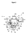
- the assembly 50 integrally incorporates the filling manifold unit 32, the supply manifold unit 42, the pressure reducing valve 43, the injector 45, the relief valves 47 and 49, and the pressure sensors P1 to P3 into a single body.
- the body 51 of the assembly 50 is made of material (e.g., SUS316L) resistant to hydrogen embrittlement and integrally incorporates various parts including the pressure reducing valve 43.
- a filling channel and a supply channel are formed in the body 51, where the filling channel communicates with the pipes 30, 31 a, and 31 b of the filling line 22 and the supply channel communicates with the pipes 40, 41a, and 41b of the supply line 23.
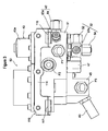
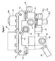
- the filling manifold unit 32 and the supply manifold unit 42 are installed next to each other in the body 51. Specifically, ports 52, 53a, 53b, and 54 of the filling manifold unit 32 are mounted under the body 51 in a direction of gravity, and ports 63a, 63b, and 64 of the supply manifold unit 42 are mounted above the ports 52, 53a, 53b, and 54.
- the ports 52, 53a, and 53b of the filling manifold unit 32 are installed at a same height level and connected with ends on one side of the filling-side pipes 30, 31a, and 31b, for example, from a horizontal direction.
- the leakage check port 54 installed pointing downward is used for leakage checks on the filling side and is normally closed with a plug. As shown in Figure 1 , the leakage check port 54 is located at one of line branch destinations of the filling line 22 and communicates with the filling line 22.
- the ports 63a and 63b of the supply manifold unit 42 are installed at a same height level and connected with ends on one side of the supply-side pipes 41 a and 41 b, for example, from a horizontal direction.
- the leakage check port 64 is used for leakage checks on the supply side and is normally closed with a plug. As shown in Figure 1 , the leakage check port 64 is located at one of line branch destinations of the supply line 23 and communicates with the supply line 23. Incidentally, although not illustrated, a port to be connected with one end of the pipe 40 is also mounted in the body 51, pointing downward.
- the assembly 50 acting as a single part functions as both the pipe fittings inserted in the filling line 22 and the supply line 23.
- mounting locations of the ports 52, 53a, 53b, and 54 in the filling manifold unit 32 may be changed.
- leakage check ports may be provided at locations of the ports 52, 53a, and 53b.
- mounting locations of the ports (63a, 63b, 64, and the like) in the supply manifold unit 42 may be changed as well.
- the leakage checks are tests conducted to verify sealing ability of junctions after pipes are assembled.
- the leakage check on the filling side involves introducing leakage check gas into the filling line 22 through the leakage check port 54 and detecting the presence or absence of gas leakage from pipe junctions (52, 53a, and 53b) and the like in the filling manifold unit 32. During the check, the manual valves 27a and 27b of the valve assemblies 26a and 26b are kept closed.
- the leakage check on the supply side involves introducing leakage check gas into the supply line 23 through the leakage check port 64 and detecting the presence or absence of gas leakage from pipe junctions (63a and 63b) and the like in the supply manifold unit 42. During the check, the shutoff valves 28a and 28b of the valve assemblies 26a and 26b are kept closed. Inert gas such as helium is used as the leakage check gas, but available leakage check methods are not limited to those which use gas.
- the pressure reducing valve 43 is mounted on the body 51 from above.
- the pressure reducing valve 43 is integrated into the body 51 when a protrusion 43a is firmly bolted to an upper face of the body 51.
- the pressure reducing valve 43 has a diaphragm, a valve disc, and a valve seat in the body 51, and a pressure-regulating spring on the protrusion 43a sticking out of the body 51.
- the diaphragm is disposed in a horizontal direction while the valve disc and the pressure-regulating spring are disposed in the direction of gravity.
- valve disc moves in an up-and-down direction, reducing the fuel gas pressure.
- the injector 45 is mounted to the body 51 from below and thereby integrated into the body 51.
- the injector 45 has, for example, a valve disc, a valve seat, a coil, an iron core, and a plunger and ejects fuel gas downward in Figures 2 and 3 .
- the valve disc is disposed in the same direction as the valve disc of the pressure reducing valve 43, i.e., in the direction of gravity.
- the coil When the coil is energized, the iron core is magnetized, attracting the plunger and the valve disc and thereby causing the valve disc to be spaced away from the valve seat. Conversely, when the coil is de-energized, the valve disc abuts the valve seat.
- a port (not shown) to be connected with one end of the pipe 40 of the supply line 23 is provided in lower part of the injector 45.
- the relief valve 47 is mounted to the body 51 from below between the pressure reducing valve 43 and the injector 45 and thereby integrated into the body 51.
- the relief valve 49 is mounted to the body 51 from below, protruding obliquely below the injector 45 and behind the body 51. When relieving the fuel gas, the relief valves 47 and 49 release the fuel gas downward and obliquely downward, respectively.
- the relief valves 47 and 49 may have the same structure, but the relief valve 49 may be made smaller in size than the relief valve 47. This is because the relief valve 49 releases fuel gas at lower pressure than does the relief valve 47.
- the pressure sensors P1 to P3 are mounted to a left flank of the body 51 and thereby integrated into the body 51.
- the pressure sensor P1 is installed in a neighborhood of the pressure reducing valve 43
- the pressure sensor P2 is installed in a neighborhood of the relief valve 47
- the pressure sensor P3 is installed in a neighborhood of the injector 45.
- the pressure sensors P1 to P3 have, for example, respective connections and pressure sensing portions and are mounted when the connectors are connected by being screwed into the body 51.
- Each of the pressure sensing portions includes, for example, a diaphragm (pressure receiving element) installed in the supply channel and a conversion element such as a strain gauge adapted to read changes received by the pressure receiving element. Based on electrical signals from the conversion elements, the controller described above measures the fuel gas pressure.
- the size of the pressure sensor P3 with the lowest pressure rating can be made the smallest, as in the case of the relief valves 47 and 49.
- Figure 4 is a plan view showing an example of layout around the fuel gas system 3 of a vehicle 100 equipped with the fuel cell system 1.
- the vehicle 100 of a typical passenger car type has the filling port 24 on the rear side of a vehicle body.
- the vehicle 100 has the fuel tanks 21a and 21 b mounted on a rear floor in lower part on the rear side and fixed to the rear floor using tank bands.
- a body frame 102 of the vehicle body includes two cross members 104a and 104b extending in a vehicle width direction and a side member 105 extending in a longitudinal direction of the vehicle.
- the side member 105 supports ends of the cross members 104a and 104b and the rear floor in conjunction with another side member (not shown).
- various component devices e.g., fuel cell 2 of the fuel cell system 1, a power control unit including the above-described controller, a traction motor (load 18) which generates a driving force of the vehicle 100, and the like are placed in front part of the vehicle body.
- a power control unit including the above-described controller
- a traction motor load 18 which generates a driving force of the vehicle 100, and the like are placed in front part of the vehicle body.
- the fuel tanks 21 a and 21 b are mounted in a horizontal position and arranged in parallel one behind the other in the longitudinal direction of the vehicle.
- the cross members 104a and 104b are positioned between the mounted fuel tanks 21a and 21b, and the assembly 50 is disposed between the cross members 104a and 104b.
- the assembly 50 is fixed by being hung by a pair of left and right brackets 110 and 111 from the cross members 104a and 104b.
- the assembly 50 includes support members 112 and 113 protruding from flanks of the body 51 in the longitudinal direction of the vehicle.
- the bracket 110 includes a vertical portion 114 extending in the vehicle width direction at approximately the same height as the body 51 of the assembly 50 and horizontal portions 116 and 117 bent to the front side from opposite bottom edges of the vertical portion 114.
- the bracket 111 includes a vertical portion 118 extending in the vehicle width direction for a distance of approximately half the length of the body 51 and a horizontal portion 119 bent to the rear side from the vertical portion 118.
- the height level of the horizontal portions 116, 117, and 119 is higher than the ports (63a, 63b, 64, etc.) of the supply manifold unit 42 in the direction of gravity, and piping space is secured for all the ports (52, 53a, 53b, 54, 63a, 63b, 64, etc.).
- the bracket 110 has an end of the support member 112 firmly bolted to its vertical portion 114, and its horizontal portions 116 and 117 fixed to an upper face of the cross member 104a via collars and bushes.
- the bracket 111 has an end of the support member 113 firmly bolted to its vertical portion 118, and its horizontal portions 116 and 117 fixed to an upper face of the cross member 104a via collars and bushes. Consequently, the assembly 50 is fixed by being hung from the cross members 104a and 104b.
- the assembly 50 is placed between the fuel tanks 21 a and 21 b and further inside the vehicle than the ends of at least one of the fuel tanks 21a and 21b.
- the fuel tanks 21a and 21b comprise cylindrical tank bodies 130a and 130b extending in the vehicle width direction and shoulders 132a and 132b formed at ends of the tank bodies 130a and 130b by reducing diameters.
- the valve assemblies 26a and 26b are screwed into tips of the shoulders 132a and 132b.
- the fuel tanks 21 a and 21b are mounted by being displaced from each other in the vehicle width direction, and the fuel tank 21 a is located closer to a flank of the vehicle than is the fuel tank 21 b.
- the assembly 50 is placed so as to face the shoulder 132b of the fuel tank 21 b and located further inside the vehicle than the valve assemblies 26a and 26b. This provides measures against damage to the fuel tanks 21 a and 21b in case the vehicle 100 is deformed due to a vehicle collision.
- the fuel tanks 21a and 21b may be mounted without displacement in the vehicle width direction.
- the assembly 50 can be disposed so as to face both the shoulders 132a and 132b and placed further inside the vehicle than the valve assemblies 26a and 26b.
- the pipes 30, 31a, and 31b on the filling side are laid out without intersecting each other.
- the pipe 30 is connected to the assembly 50 by extending from the filling port 24 in a crank-like fashion.
- the pipes 31a and 31 b are connected to the assembly 50 by extending, respectively, from the assemblies 26a and 26b and running meanderingly.
- the pipes 40, 41 a, and 41 b on the supply side the pipes 41 a and 41 b are connected to the assembly 50 by extending, respectively, from the assemblies 26a and 26b and running meanderingly.
- the pipes 41 a and 41b are installed at a same height level higher than the pipes 31 a and 31b in the direction of gravity.
- An intermediate portion of the pipe 41a is located right above an intermediate portion of the pipe 31a.
- the pipe 40 is laid with bends, extending from the assembly 50 and running below the pipes 31a 31b, 41a, and 41b. Part of the pipe 40 intersects the pipes 41 a and 31 a below the intermediate portions of the pipes 41 a and 31 a
- the assembly 50 which functions as pipe fittings of both the filling line 22 and the supply line 23 requires only a single body for the pipe fittings. Also, the assembly 50, which integrates the pressure reducing valve 43, injector 45, and relief valves 47 and 49, allows a body to be shared among these parts.
- the ports (52, 53a, and 53b) connected with the pipes of the filling line 22 and the ports (63a and 63b) connected with the pipes of the supply line 23 are provided by being separated into upper and lower parts. This makes it possible to make pipe connections intensively by securing piping spaces for the pipes appropriately in the assembly 50.
- the ports (52, 53a, and 53b) for the filling line 22 are located below the ports (63a and 63b) for the supply line 23. Consequently, tool space for assembling pipes on the filling line 22 can be secured. This makes it easier to assemble the pipes 30, 31 a, and 31 b onto the assembly 50 after the pipes 40, 41a, and 41b of the supply line 23 are assembled onto the assembly 50 when performing an assembly operation by manipulating a fastening tool from below the vehicle 100.
- the present embodiment improves mountability on the vehicle 100 because the assembly 50 into which multiple pars are integrated can be treated as a single part. In particular, mounting sites on the vehicle 100 can be reduced, achieving savings in mounting space on the vehicle. This means increased flexibility of piping layout resulting in simplification of piping layout.
- the assembly 50 is placed between the fuel tanks 21 a and 21 b, facing the shoulder of at least one of the fuel tanks 21 a and 21 b. This makes it possible to place the assembly 50 using dead space between the fuel tanks 21a and 21b effectively. This reduces damage to the fuel tanks 21a and 21b even in case the vehicle 100 is deformed, for example, by a rear-end collision.
- the pipes 30, 31 a, 31 b, 40, 41, and 41 b connected to the assembly 50 run with bends, the pipes can absorb shocks of a vehicle collision.
- the pressure reducing valve 43 and the pressure sensors P1 and P2 are integrated into the assembly 50, the primary pressure or secondary pressure of the pressure reducing valve 43 can be monitored and controlled. Also, since the pressure reducing valve 43 is integrated with the pressure sensor P2 for medium pressure, improved measurement accuracy can be exhibited in case of failure. Similarly, since the injector 45 is integrated with the pressure sensors P2 and P3, the primary pressure or secondary pressure of the injector 45 can be monitored and controlled, and improved measurement accuracy can be exhibited in case of failure. Also, the leakage check ports 54 and 64 are installed in the assembly 50. This makes it possible to check pipe junctions in the filling line 22 and the supply line 23 as well as the filling line 22 and the supply line 23 themselves for leakage using the assembly 50 effectively.
- the parts to be integrated into the assembly 50 are not limited to those described above (the filling manifold unit 32, the supply manifold unit 42, the pressure reducing valve 43, the injector 45, the relief valves 47 and 49, and the pressure sensors P1 to P3), and other parts may be added.
- the pressure sensor may be integrated into the assembly 50.
- the assembly 50 it is sufficient if at least the pressure reducing valve 43 and the one of the pressure sensors P1 and P2 are integrated into the assembly 50. Therefore, at least one of the injector 45, the relief valves 47 and 49, and the pressure sensor P3 may be omitted from the assembly 50. Also, at least one of the leakage check ports 54 and 64 may be omitted from the assembly 50. Incidentally, even if the leakage check ports 54 and 64 do not exist, the assembly 50 can be said to have the branch points 22a and 23a of the filling line 22 and the supply line 23.
- a valve assembly 26c of a fuel tank 21 c includes a manual valve 27c and shutoff valve 28c as in the case of the fuel tanks 21 a and 21 b described above.
- the filling line 22 includes two pipes in total: pipes 30 and 31 c.
- the pipe 30 connects the filling port 24 with the port 52 of the filling manifold unit 32 while the pipe 31c connects a port 53c of the filling manifold unit 32 with the fuel tank 21c.
- the filling manifold unit 32 has a line branch point 22a for the filling line 22 and has a leakage check port 54 at a branch destination of the filling line 22.
- the supply line 23 includes two pipes in total: pipes 40 and 41 c.
- the pipe 40 connects the fuel cell 2 with a port 62 of the supply manifold unit 42 while the pipe 41 c connects a port 63c of the supply manifold unit 42 with the fuel tank 21c.
- the supply manifold unit 42 has a line branch point 23a for the supply line 23 and has a leakage check port 64 at a branch destination of the supply line 23.
- An assembly 50c integrally incorporates multiple parts surrounded by a chain double-dashed line in Figure 5 , i.e., the filling manifold unit 32, the supply manifold unit 42, the pressure reducing valve 43, the injector 45, the relief valves 47 and 49, and the pressure sensors P1 to P3 into a single body.
- the assembly 50c has a configuration obtained by omitting the filling-side port 53a and the supply-side port 63a from the assembly 50 shown in Figures 2 and 3 . That is, the filling-side port 53a and the supply-side port 63a on the front side of the vehicle have been omitted.
- description of a specific configuration resulting from integration of the assembly 50c will be omitted herein.
- the assembly 50c can be placed, for example, further on the forward side of the vehicle than the fuel tank 21c by taking rear-end collisions of the vehicle into consideration. In that case, preferably the assembly 50c is placed facing a shoulder of the fuel tank 21 c.
- the pipes 30, 31c, 40, and 41c can be run with bends from the viewpoint of shock absorption.
- the second embodiment described above provides advantages similar to those of the first embodiment, i.e., improves parts commonality, assembly ease, and mountability.
- first embodiment can also be applied to the second embodiment as appropriate.
- parts e.g., a pressure sensor installed on the filling line 22
- the leakage check port 54 may be omitted from the assembly 50c. If the leakage check port 54 does not exist, the assembly 50c does not have the branch point 22a for the filling line 22. In that case, the assembly 50c does not have to integrally include the filling manifold unit 32.
- the assembly 50c is integrated with at least the pressure reducing valve 43 and one of the pressure sensors P1 and P2.
- the present embodiment is configured such that the two leakage check ports 54 and 64 in the assembly 50 or 50c are combined into one and that leakage check gas can be introduced into the filling line 22 and the supply line 23 through the single leakage check port.
- drawings of the third embodiment are omitted.
- a communicating channel which interconnects the filling channel and the supply channel in the body 51 of the assembly 50 or 50c is formed in the body 51 and a valve is installed to open and close the communicating channel. Except during leakage checks, the valve is normally closed to keep the filling channel and the supply channel from communicating with each other in the body 51. On the other hand, during a leakage check, the valve is opened to introduce leakage check gas through the single leakage check port. Consequently, the leakage check gas flows through the filling channel and supply channel and then the filling line 22 and the supply line 23. This makes it possible to check all the pipe junctions and the like of the assembly 50 or 50c for gas leakage.
- the third embodiment provides the advantage of being able to practically halve the man-hours of leakage checking.
- the fuel cell system according to the present invention can be applied not only to the fuel cell systems 1 and 1 c described above, but also to a system which uses natural gas as fuel and a vehicle equipped with such a system for example.
Landscapes
- Engineering & Computer Science (AREA)
- Chemical & Material Sciences (AREA)
- Life Sciences & Earth Sciences (AREA)
- Sustainable Development (AREA)
- Sustainable Energy (AREA)
- Chemical Kinetics & Catalysis (AREA)
- Manufacturing & Machinery (AREA)
- Electrochemistry (AREA)
- General Chemical & Material Sciences (AREA)
- Combustion & Propulsion (AREA)
- Transportation (AREA)
- Mechanical Engineering (AREA)
- Fuel Cell (AREA)
- Filling Or Discharging Of Gas Storage Vessels (AREA)
- Cooling, Air Intake And Gas Exhaust, And Fuel Tank Arrangements In Propulsion Units (AREA)
Claims (14)
- Kraftstoffsystem (1), aufweisend eine Kraftstoffspeicherquelle (21a, 21b, 21c), eine Tankleitung (22), die darauf ausgelegt ist, die Kraftstoffspeicherquelle (21a, 21b, 21c) mit einem Betankungsanschluss (24) zu verbinden, eine Zuführleitung (23), die darauf ausgelegt ist, die Kraftstoffspeicherquelle (21a, 21b, 21c) mit einem Kraftstoffziel (2) zu verbinden, und ein Druckreduzierungsventil (43), das in der Zuführleitung (23) installiert ist, wobei das Kraftstoffsystem (1) ferner aufweist:zumindest einen ersten Drucksensor (P1) und/oder einen zweiten Drucksensor (P2), der darauf ausgelegt ist, einen primären bzw. sekundären Druck des Druckreduzierungsventils (43) zu erfassen; undeine Anordnung (50; 50c), in die das Druckreduzierungsventil (43) und zumindest entweder der erste Drucksensor (P1) und/oder der zweite Drucksensor (P2) integriert sind, wobeidie Anordnung (50; 50c) einen Körper (51), der einen Zuführkanal aufweist, der mit Rohren (40, 4a, 41b; 40, 41c) der Zuführleitung (23) kommuniziert, Anschlüsse (63a, 63b; 62, 63c) zum Verbinden der Rohre (40, 41a, 41b; 40, 41c) der Zuführleitung (23), einen Leitungsabzweigungspunkt (23a) für die Zuführleitung (23), einen Betankungskanal, der mit Rohren (30, 31a, 31b; 30, 31c) der Betankungsleitung (22) kommuniziert, und Anschlüsse (52, 53a, 53b; 52, 53c) zum Verbinden der Rohre (30, 31a, 31b; 30, 31c) der Zuführleitung (22) beinhaltet, so dass die Anordnung (50; 50c) als eine Rohrfassung (32), die in die Zuführleitung (23) eingefügt ist, und eine Rohrfassung (42), die in die Betankungsleitung (22) eingefügt ist, fungiert.
- Kraftstoffsystem (1) nach Anspruch 1, wobei die Anordnung (50; 50c) einen ersten Leckagenprüfanschluss (64) an einem Abzweigungsziel von der Zuführleitung (23) aufweist.
- Kraftstoffsystem (1) nach Anspruch 1 oder 2, wobei das Druckreduzierungsventil (43) und der erste Drucksensor (P1) auf einer Stromabwärtsseite des Abzweigüngspunkts (23a), die der Seite des Kraftstoffziels (2) entspricht, in die Anordnung (50; 50c) integriert sind.
- Kraftstoffsystem (1) nach Anspruch 3, wobei ein Injektor (45), der auf einer Stromabwärtsseite des Druckreduzierungsventils (43) installiert ist und darauf ausgelegt ist, Kraftstoff einzuspritzen, weiter in die Anordnung (50; 50c) integriert ist.
- Kraftstoffsystem (1) nach Anspruch 4, wobei der zweite Drucksensor (P2) und ein dritter Drucksensor (P3) darauf ausgelegt sind, den primären bzw. sekundären Druck des Injektors (45) zu erfassen, und in die Anordnung (50; 50c) integriert sind.
- Kraftstoffsystem (1) nach Anspruch 4 oder 5, wobei ein Überdruckventil (47), das darauf ausgelegt ist, zwischen dem Druckreduzierungsventil (43) und dem Injektor (45) auf der Zuführleitung (23) zu kommunizieren, weiter in die Anordnung (50; 50c) integriert ist.
- Kraftstoffsystem (1) nach einem der Ansprüche 1 bis 6, wobei der erste Drucksensor (P1) darauf ausgelegt ist, Druck in der Kraftstoffspeicherquelle (21 a, 21b; 21 c) zu erfassen.
- Kraftstoffsystem (1) nach einem der Ansprüche 1 bis 7, wobei die Anordnung (50; 50c) einen Leitungsabzweigungspunkt (22a) für die Betankungsleitung (22) aufweist und einen zweiten Leckagenprüfanschluss (54) an einem Abzweigungsziel von der Betankungsleitung (22) aufweist.
- Kraftstoffsystem nach einem der Ansprüche 1 bis 8, wobei sich in der Anordnung (50; 50c) die Verbindungen von Rohren (40, 41a, 41b; 40, 41c) der Zuführleitung (23) in einer Richtung der Schwerkraft über den Verbindungen von Rohren (30, 31a, 31b; 30, 31c) der Betankungsleitung (22) befinden.
- Kraftstoffsystem (1) nach einem der Ansprüche 1 bis 9, wobei:eine Mehrzahl an Kraftstoffspeicherquellen (21 a, 21 b) vorgesehen ist; unddie von dem Kraftstoffziel (2) kommende Zuführleitung in der Anordnung (50) verzweigt ist und parallel mit jeder der Kraftstoffspeicherquellen (21a, 21b) verbunden ist.
- Kraftstoffsystem (1) nach Anspruch 10, wobei die von dem Betankungsanschluss (24) kommende Betankungsleitung (22) in der Anordnung (50) verzweigt ist und parallel mit jeder der Kraftstoffspeicherquellen (21a, 21b) verbunden ist.
- Kraftstoffsystem (1) nach Anspruch 10 oder 11, wobei:die Kraftstoffspeicherquellen (21a, 21b) Hochdrucktanks sind, die jeweils einen Tankkörper und einen Ansatz aufweisen, der sich mit einem Ende des Tankkörpers fortsetzt; undsich die Anordnung (50) zwischen benachbarten Hochdrucktanks befindet, damit sie dem Ansatz von zumindest einem der Hochdrucktanks gegenüberliegt.
- Kraftstoffsystem (1) nach einem der Ansprüche 1 bis 12, wobei das Kraftstoffziel (2) eine Brennstoffzelle ist.
- Fahrzeug, das mit dem Kraftstoffsystem (1) nach einem der Ansprüche 1 bis 13 ausgestattet ist.
Applications Claiming Priority (1)
| Application Number | Priority Date | Filing Date | Title |
|---|---|---|---|
| PCT/JP2009/063066 WO2011010366A1 (ja) | 2009-07-21 | 2009-07-21 | 燃料システム及び車両 |
Publications (3)
| Publication Number | Publication Date |
|---|---|
| EP2457762A1 EP2457762A1 (de) | 2012-05-30 |
| EP2457762A4 EP2457762A4 (de) | 2013-09-18 |
| EP2457762B1 true EP2457762B1 (de) | 2014-12-10 |
Family
ID=43498854
Family Applications (1)
| Application Number | Title | Priority Date | Filing Date |
|---|---|---|---|
| EP09847551.0A Active EP2457762B1 (de) | 2009-07-21 | 2009-07-21 | Kraftstoffsystem und fahrzeug |
Country Status (5)
| Country | Link |
|---|---|
| US (1) | US8844662B2 (de) |
| EP (1) | EP2457762B1 (de) |
| JP (1) | JP5131612B2 (de) |
| CN (1) | CN102470750B (de) |
| WO (1) | WO2011010366A1 (de) |
Families Citing this family (20)
| Publication number | Priority date | Publication date | Assignee | Title |
|---|---|---|---|---|
| JP5736871B2 (ja) * | 2011-03-17 | 2015-06-17 | トヨタ自動車株式会社 | 燃料電池システム |
| US9911994B2 (en) * | 2011-05-26 | 2018-03-06 | GM Global Technology Operations LLC | Piezoelectric injector for fuel cell |
| DE102012218857A1 (de) | 2012-10-16 | 2014-04-17 | Bayerische Motoren Werke Aktiengesellschaft | Verfahren zum Befüllen einer Kraftstoffspeicheranlage eines Kraftfahrzeugs |
| JP6207477B2 (ja) * | 2014-07-03 | 2017-10-04 | 愛三工業株式会社 | 燃料供給ユニット |
| US9579969B2 (en) * | 2014-07-25 | 2017-02-28 | Oshkosh Corporation | Refuse vehicle having tailgate-mounted CNG tanks |
| US9682618B2 (en) | 2015-02-05 | 2017-06-20 | Agility Fuel Systems Llc | Manual emergency gas release system |
| JP2017025727A (ja) * | 2015-07-17 | 2017-02-02 | 愛三工業株式会社 | 燃料供給ユニット |
| DE102015224243A1 (de) * | 2015-12-03 | 2017-06-08 | Bayerische Motoren Werke Aktiengesellschaft | Kraftfahrzeug mit zumindest zwei Tanks für die Aufnahme von Brennstoff unter hohem Druck |
| CN105863862B (zh) * | 2016-04-22 | 2018-08-31 | 潍柴动力股份有限公司 | 一种喷油器、共轨喷油系统及喷油方法 |
| RU170566U1 (ru) * | 2016-09-22 | 2017-04-28 | Публичное акционерное общество "КАМАЗ" | Топливная система транспортного средства |
| US10914401B2 (en) | 2017-01-10 | 2021-02-09 | The Heil Co. | Fuel monitoring system |
| KR101918533B1 (ko) * | 2017-06-09 | 2019-02-11 | 주식회사 유니크 | 차량의 수소 충전 시스템 및 충전 방법 |
| DE102017213525A1 (de) * | 2017-08-03 | 2019-02-07 | Bayerische Motoren Werke Aktiengesellschaft | Druckbehältersystem mit einem Betankungszugang und mehreren Druckbehältern |
| DE102017213526A1 (de) * | 2017-08-03 | 2019-02-07 | Bayerische Motoren Werke Aktiengesellschaft | Druckbehältersystem mit mehreren Druckbehältern und einem Druckwandler |
| PL3672823T3 (pl) | 2017-09-14 | 2024-01-03 | Agility Fuel Systems Llc | Systemy do monitorowania komponentów układu paliwa lotnego |
| DE102018000756A1 (de) | 2018-01-31 | 2019-01-24 | Daimler Ag | Druckgasbehälter und Druckgasspeicher |
| US11207974B2 (en) * | 2018-09-21 | 2021-12-28 | The Heil Co. | Multiple gas tank assembly with individual pressure monitoring |
| DE102019128427A1 (de) * | 2019-10-22 | 2021-04-22 | Audi Ag | Ventileinrichtung und Gasdruckspeicher |
| WO2021108387A1 (en) | 2019-11-25 | 2021-06-03 | Agility Fuel Systems Llc | Improved pressure relief device |
| CN113561763A (zh) * | 2020-04-28 | 2021-10-29 | 未势能源科技有限公司 | 燃料处理单元和具有它的燃料储存和供应系统 |
Family Cites Families (25)
| Publication number | Priority date | Publication date | Assignee | Title |
|---|---|---|---|---|
| US4556077A (en) * | 1983-12-20 | 1985-12-03 | Allied Corporation | Switching valve for a fuel supply system |
| US5794979A (en) * | 1994-09-30 | 1998-08-18 | Honda Giken Kogyo Kabushiki Kaisha | Method and structure for mounting a fuel tank |
| JP3111152B2 (ja) | 1994-09-30 | 2000-11-20 | 本田技研工業株式会社 | 燃料タンク取付方法および取付構造 |
| JP2943980B2 (ja) * | 1997-07-24 | 1999-08-30 | 本田技研工業株式会社 | ガス燃料用配管装置 |
| JPH11294698A (ja) | 1998-04-10 | 1999-10-29 | Nippon Sanso Kk | ガス供給設備 |
| JP3360133B2 (ja) * | 1998-11-11 | 2002-12-24 | 株式会社フジキン | 流体制御装置用継手部材およびその製造方法 |
| JP4489275B2 (ja) * | 2000-10-06 | 2010-06-23 | アドバンスド エナジー ジャパン株式会社 | 流量計測機能を具えた圧力制御装置 |
| JP2002206696A (ja) * | 2001-01-09 | 2002-07-26 | Honda Motor Co Ltd | 高圧ガス供給システム |
| JP4774634B2 (ja) | 2001-06-15 | 2011-09-14 | トヨタ自動車株式会社 | 気体貯蔵システム |
| US6824911B2 (en) | 2002-04-18 | 2004-11-30 | Altergy Systems | Integrated fuel cell power system |
| JP3746758B2 (ja) * | 2002-11-11 | 2006-02-15 | 本田技研工業株式会社 | 燃料電池車両の配管類配索構造 |
| US7878280B2 (en) * | 2003-04-09 | 2011-02-01 | Bloom Energy Corporation | Low pressure hydrogen fueled vehicle and method of operating same |
| JP4081430B2 (ja) * | 2003-11-19 | 2008-04-23 | 本田技研工業株式会社 | 燃料電池車両 |
| US20050202292A1 (en) * | 2004-03-10 | 2005-09-15 | Richards William R. | Portable fuel cell power supply |
| JP4821608B2 (ja) | 2004-03-17 | 2011-11-24 | トヨタ自動車株式会社 | 燃料電池システム |
| JP2006200564A (ja) | 2005-01-18 | 2006-08-03 | Toyota Motor Corp | 液体燃料供給システム |
| DE112006000247B4 (de) | 2005-01-26 | 2010-09-02 | Toyota Jidosha Kabushiki Kaisha, Toyota-shi | Brennstofftank-System |
| US7377294B2 (en) * | 2005-04-20 | 2008-05-27 | Honda Motor Co., Ltd. | Gas cooling methods for high pressure fuel storage tanks on vehicles powered by compressed natural gas or hydrogen |
| US7520916B2 (en) * | 2005-07-25 | 2009-04-21 | Bloom Energy Corporation | Partial pressure swing adsorption system for providing hydrogen to a vehicle fuel cell |
| JP4744285B2 (ja) * | 2005-12-19 | 2011-08-10 | 本田技研工業株式会社 | 水素自動車のガスの使用及び補給システム |
| JP4941730B2 (ja) * | 2007-03-08 | 2012-05-30 | トヨタ自動車株式会社 | 燃料供給装置及び車両 |
| JP5196292B2 (ja) * | 2007-07-13 | 2013-05-15 | トヨタ自動車株式会社 | 燃料電池車両 |
| JP5096864B2 (ja) | 2007-10-11 | 2012-12-12 | サーパス工業株式会社 | 流体機器ユニット構造 |
| JP4655082B2 (ja) | 2007-11-16 | 2011-03-23 | トヨタ自動車株式会社 | 燃料電池システム |
| DE112009005091B8 (de) | 2009-07-21 | 2015-09-17 | Toyota Jidosha Kabushiki Kaisha | Brennstoffsystem und Fahrzeug |
-
2009
- 2009-07-21 EP EP09847551.0A patent/EP2457762B1/de active Active
- 2009-07-21 US US13/386,163 patent/US8844662B2/en active Active
- 2009-07-21 JP JP2011523507A patent/JP5131612B2/ja active Active
- 2009-07-21 CN CN200980160556.4A patent/CN102470750B/zh active Active
- 2009-07-21 WO PCT/JP2009/063066 patent/WO2011010366A1/ja not_active Ceased
Also Published As
| Publication number | Publication date |
|---|---|
| JP5131612B2 (ja) | 2013-01-30 |
| EP2457762A4 (de) | 2013-09-18 |
| US20120115061A1 (en) | 2012-05-10 |
| CN102470750B (zh) | 2015-11-25 |
| US8844662B2 (en) | 2014-09-30 |
| WO2011010366A1 (ja) | 2011-01-27 |
| JPWO2011010366A1 (ja) | 2012-12-27 |
| EP2457762A1 (de) | 2012-05-30 |
| CN102470750A (zh) | 2012-05-23 |
Similar Documents
| Publication | Publication Date | Title |
|---|---|---|
| EP2457762B1 (de) | Kraftstoffsystem und fahrzeug | |
| US8464818B2 (en) | Fuel system and vehicle | |
| CN101678757B (zh) | 燃料电池搭载车辆 | |
| US7426935B2 (en) | Method of discharging high pressure storage vessels | |
| CA2870108C (en) | Fuel cell vehicle | |
| KR101136498B1 (ko) | 연료전지시스템 | |
| CN214625117U (zh) | 车辆的供氢系统和具有其的车辆 | |
| CN105283336B (zh) | 电动车辆 | |
| CN101568761B (zh) | 燃料供给装置 | |
| US20220013796A1 (en) | Fuel cell system and fuel cell system for vehicle | |
| JP5348606B2 (ja) | 燃料電池システム | |
| CN108206290B (zh) | 燃料电池系统 | |
| CN212062589U (zh) | 一种集成式燃料电池供氢控制面板系统 | |
| KR102531684B1 (ko) | 수소탱크를 포함하는 수소차량의 충전용 매니폴드 및 이를 이용한 방법 | |
| JP2009105076A (ja) | 燃料電池システム | |
| JP5007931B2 (ja) | 燃料タンクの支持装置 | |
| JP4952670B2 (ja) | 移動体 | |
| JP2009021150A (ja) | 燃料電池システムおよび燃料電池車両 | |
| CN222610932U (zh) | 车辆的动力系统以及车辆 | |
| US20260124936A1 (en) | Architecture for fuel cell mining trucks | |
| EP4737164A1 (de) | Architektur für brennstoffzellen-mining-lastkraftwagen | |
| JP2026015836A (ja) | 車両の燃料タンクシステム | |
| JP2025018311A (ja) | 燃料電池車両 | |
| CN116885232A (zh) | 一种共轨装置、介质存储系统及车辆 | |
| JP2026015835A (ja) | 車両の燃料タンクシステム |
Legal Events
| Date | Code | Title | Description |
|---|---|---|---|
| PUAI | Public reference made under article 153(3) epc to a published international application that has entered the european phase |
Free format text: ORIGINAL CODE: 0009012 |
|
| 17P | Request for examination filed |
Effective date: 20120221 |
|
| AK | Designated contracting states |
Kind code of ref document: A1 Designated state(s): AT BE BG CH CY CZ DE DK EE ES FI FR GB GR HR HU IE IS IT LI LT LU LV MC MK MT NL NO PL PT RO SE SI SK SM TR |
|
| DAX | Request for extension of the european patent (deleted) | ||
| RAP1 | Party data changed (applicant data changed or rights of an application transferred) |
Owner name: TOYOTA JIDOSHA KABUSHIKI KAISHA |
|
| A4 | Supplementary search report drawn up and despatched |
Effective date: 20130820 |
|
| RIC1 | Information provided on ipc code assigned before grant |
Ipc: B60K 15/01 20060101ALI20130813BHEP Ipc: H01M 8/00 20060101ALI20130813BHEP Ipc: F16L 41/00 20060101ALI20130813BHEP Ipc: F17C 5/06 20060101ALI20130813BHEP Ipc: B60K 15/03 20060101AFI20130813BHEP Ipc: F17C 13/04 20060101ALI20130813BHEP Ipc: F17C 7/00 20060101ALI20130813BHEP Ipc: F16K 27/00 20060101ALI20130813BHEP Ipc: H01M 8/04 20060101ALI20130813BHEP |
|
| RIC1 | Information provided on ipc code assigned before grant |
Ipc: H01M 8/00 20060101ALI20140522BHEP Ipc: F16L 41/00 20060101ALI20140522BHEP Ipc: H01M 8/04 20060101ALI20140522BHEP Ipc: F17C 13/04 20060101ALI20140522BHEP Ipc: F17C 7/00 20060101ALI20140522BHEP Ipc: B60K 15/03 20060101AFI20140522BHEP Ipc: B60K 15/01 20060101ALI20140522BHEP Ipc: F16K 27/00 20060101ALI20140522BHEP Ipc: F17C 5/06 20060101ALI20140522BHEP |
|
| GRAP | Despatch of communication of intention to grant a patent |
Free format text: ORIGINAL CODE: EPIDOSNIGR1 |
|
| INTG | Intention to grant announced |
Effective date: 20140704 |
|
| RIN1 | Information on inventor provided before grant (corrected) |
Inventor name: TSUBOKAWA, TAKEHISA |
|
| GRAP | Despatch of communication of intention to grant a patent |
Free format text: ORIGINAL CODE: EPIDOSNIGR1 |
|
| GRAS | Grant fee paid |
Free format text: ORIGINAL CODE: EPIDOSNIGR3 |
|
| INTG | Intention to grant announced |
Effective date: 20141017 |
|
| GRAA | (expected) grant |
Free format text: ORIGINAL CODE: 0009210 |
|
| AK | Designated contracting states |
Kind code of ref document: B1 Designated state(s): AT BE BG CH CY CZ DE DK EE ES FI FR GB GR HR HU IE IS IT LI LT LU LV MC MK MT NL NO PL PT RO SE SI SK SM TR |
|
| REG | Reference to a national code |
Ref country code: GB Ref legal event code: FG4D |
|
| REG | Reference to a national code |
Ref country code: CH Ref legal event code: EP |
|
| REG | Reference to a national code |
Ref country code: IE Ref legal event code: FG4D |
|
| REG | Reference to a national code |
Ref country code: AT Ref legal event code: REF Ref document number: 700469 Country of ref document: AT Kind code of ref document: T Effective date: 20150115 |
|
| REG | Reference to a national code |
Ref country code: DE Ref legal event code: R096 Ref document number: 602009028321 Country of ref document: DE Effective date: 20150122 |
|
| REG | Reference to a national code |
Ref country code: AT Ref legal event code: MK05 Ref document number: 700469 Country of ref document: AT Kind code of ref document: T Effective date: 20141210 Ref country code: NL Ref legal event code: VDEP Effective date: 20141210 |
|
| REG | Reference to a national code |
Ref country code: DE Ref legal event code: R084 Ref document number: 602009028321 Country of ref document: DE |
|
| REG | Reference to a national code |
Ref country code: NL Ref legal event code: VDEP Effective date: 20141210 |
|
| PG25 | Lapsed in a contracting state [announced via postgrant information from national office to epo] |
Ref country code: LT Free format text: LAPSE BECAUSE OF FAILURE TO SUBMIT A TRANSLATION OF THE DESCRIPTION OR TO PAY THE FEE WITHIN THE PRESCRIBED TIME-LIMIT Effective date: 20141210 Ref country code: ES Free format text: LAPSE BECAUSE OF FAILURE TO SUBMIT A TRANSLATION OF THE DESCRIPTION OR TO PAY THE FEE WITHIN THE PRESCRIBED TIME-LIMIT Effective date: 20141210 Ref country code: FI Free format text: LAPSE BECAUSE OF FAILURE TO SUBMIT A TRANSLATION OF THE DESCRIPTION OR TO PAY THE FEE WITHIN THE PRESCRIBED TIME-LIMIT Effective date: 20141210 Ref country code: NO Free format text: LAPSE BECAUSE OF FAILURE TO SUBMIT A TRANSLATION OF THE DESCRIPTION OR TO PAY THE FEE WITHIN THE PRESCRIBED TIME-LIMIT Effective date: 20150310 |
|
| REG | Reference to a national code |
Ref country code: LT Ref legal event code: MG4D |
|
| PG25 | Lapsed in a contracting state [announced via postgrant information from national office to epo] |
Ref country code: HR Free format text: LAPSE BECAUSE OF FAILURE TO SUBMIT A TRANSLATION OF THE DESCRIPTION OR TO PAY THE FEE WITHIN THE PRESCRIBED TIME-LIMIT Effective date: 20141210 Ref country code: AT Free format text: LAPSE BECAUSE OF FAILURE TO SUBMIT A TRANSLATION OF THE DESCRIPTION OR TO PAY THE FEE WITHIN THE PRESCRIBED TIME-LIMIT Effective date: 20141210 Ref country code: GR Free format text: LAPSE BECAUSE OF FAILURE TO SUBMIT A TRANSLATION OF THE DESCRIPTION OR TO PAY THE FEE WITHIN THE PRESCRIBED TIME-LIMIT Effective date: 20150311 Ref country code: SE Free format text: LAPSE BECAUSE OF FAILURE TO SUBMIT A TRANSLATION OF THE DESCRIPTION OR TO PAY THE FEE WITHIN THE PRESCRIBED TIME-LIMIT Effective date: 20141210 Ref country code: LV Free format text: LAPSE BECAUSE OF FAILURE TO SUBMIT A TRANSLATION OF THE DESCRIPTION OR TO PAY THE FEE WITHIN THE PRESCRIBED TIME-LIMIT Effective date: 20141210 |
|
| REG | Reference to a national code |
Ref country code: DE Ref legal event code: R084 Ref document number: 602009028321 Country of ref document: DE Effective date: 20150417 |
|
| PG25 | Lapsed in a contracting state [announced via postgrant information from national office to epo] |
Ref country code: NL Free format text: LAPSE BECAUSE OF FAILURE TO SUBMIT A TRANSLATION OF THE DESCRIPTION OR TO PAY THE FEE WITHIN THE PRESCRIBED TIME-LIMIT Effective date: 20141210 |
|
| PG25 | Lapsed in a contracting state [announced via postgrant information from national office to epo] |
Ref country code: RO Free format text: LAPSE BECAUSE OF FAILURE TO SUBMIT A TRANSLATION OF THE DESCRIPTION OR TO PAY THE FEE WITHIN THE PRESCRIBED TIME-LIMIT Effective date: 20141210 Ref country code: CZ Free format text: LAPSE BECAUSE OF FAILURE TO SUBMIT A TRANSLATION OF THE DESCRIPTION OR TO PAY THE FEE WITHIN THE PRESCRIBED TIME-LIMIT Effective date: 20141210 Ref country code: EE Free format text: LAPSE BECAUSE OF FAILURE TO SUBMIT A TRANSLATION OF THE DESCRIPTION OR TO PAY THE FEE WITHIN THE PRESCRIBED TIME-LIMIT Effective date: 20141210 Ref country code: SK Free format text: LAPSE BECAUSE OF FAILURE TO SUBMIT A TRANSLATION OF THE DESCRIPTION OR TO PAY THE FEE WITHIN THE PRESCRIBED TIME-LIMIT Effective date: 20141210 Ref country code: PT Free format text: LAPSE BECAUSE OF FAILURE TO SUBMIT A TRANSLATION OF THE DESCRIPTION OR TO PAY THE FEE WITHIN THE PRESCRIBED TIME-LIMIT Effective date: 20150410 |
|
| PG25 | Lapsed in a contracting state [announced via postgrant information from national office to epo] |
Ref country code: PL Free format text: LAPSE BECAUSE OF FAILURE TO SUBMIT A TRANSLATION OF THE DESCRIPTION OR TO PAY THE FEE WITHIN THE PRESCRIBED TIME-LIMIT Effective date: 20141210 Ref country code: IS Free format text: LAPSE BECAUSE OF FAILURE TO SUBMIT A TRANSLATION OF THE DESCRIPTION OR TO PAY THE FEE WITHIN THE PRESCRIBED TIME-LIMIT Effective date: 20150410 |
|
| REG | Reference to a national code |
Ref country code: DE Ref legal event code: R097 Ref document number: 602009028321 Country of ref document: DE |
|
| PLBE | No opposition filed within time limit |
Free format text: ORIGINAL CODE: 0009261 |
|
| STAA | Information on the status of an ep patent application or granted ep patent |
Free format text: STATUS: NO OPPOSITION FILED WITHIN TIME LIMIT |
|
| PG25 | Lapsed in a contracting state [announced via postgrant information from national office to epo] |
Ref country code: DK Free format text: LAPSE BECAUSE OF FAILURE TO SUBMIT A TRANSLATION OF THE DESCRIPTION OR TO PAY THE FEE WITHIN THE PRESCRIBED TIME-LIMIT Effective date: 20141210 |
|
| 26N | No opposition filed |
Effective date: 20150911 |
|
| PG25 | Lapsed in a contracting state [announced via postgrant information from national office to epo] |
Ref country code: IT Free format text: LAPSE BECAUSE OF FAILURE TO SUBMIT A TRANSLATION OF THE DESCRIPTION OR TO PAY THE FEE WITHIN THE PRESCRIBED TIME-LIMIT Effective date: 20141210 |
|
| PG25 | Lapsed in a contracting state [announced via postgrant information from national office to epo] |
Ref country code: MC Free format text: LAPSE BECAUSE OF FAILURE TO SUBMIT A TRANSLATION OF THE DESCRIPTION OR TO PAY THE FEE WITHIN THE PRESCRIBED TIME-LIMIT Effective date: 20141210 Ref country code: SI Free format text: LAPSE BECAUSE OF FAILURE TO SUBMIT A TRANSLATION OF THE DESCRIPTION OR TO PAY THE FEE WITHIN THE PRESCRIBED TIME-LIMIT Effective date: 20141210 |
|
| REG | Reference to a national code |
Ref country code: CH Ref legal event code: PL |
|
| GBPC | Gb: european patent ceased through non-payment of renewal fee |
Effective date: 20150721 |
|
| PG25 | Lapsed in a contracting state [announced via postgrant information from national office to epo] |
Ref country code: LU Free format text: LAPSE BECAUSE OF FAILURE TO SUBMIT A TRANSLATION OF THE DESCRIPTION OR TO PAY THE FEE WITHIN THE PRESCRIBED TIME-LIMIT Effective date: 20150721 |
|
| REG | Reference to a national code |
Ref country code: IE Ref legal event code: MM4A |
|
| PG25 | Lapsed in a contracting state [announced via postgrant information from national office to epo] |
Ref country code: GB Free format text: LAPSE BECAUSE OF NON-PAYMENT OF DUE FEES Effective date: 20150721 Ref country code: CH Free format text: LAPSE BECAUSE OF NON-PAYMENT OF DUE FEES Effective date: 20150731 Ref country code: LI Free format text: LAPSE BECAUSE OF NON-PAYMENT OF DUE FEES Effective date: 20150731 |
|
| REG | Reference to a national code |
Ref country code: FR Ref legal event code: ST Effective date: 20160331 |
|
| PG25 | Lapsed in a contracting state [announced via postgrant information from national office to epo] |
Ref country code: BE Free format text: LAPSE BECAUSE OF FAILURE TO SUBMIT A TRANSLATION OF THE DESCRIPTION OR TO PAY THE FEE WITHIN THE PRESCRIBED TIME-LIMIT Effective date: 20141210 Ref country code: FR Free format text: LAPSE BECAUSE OF NON-PAYMENT OF DUE FEES Effective date: 20150731 |
|
| PG25 | Lapsed in a contracting state [announced via postgrant information from national office to epo] |
Ref country code: IE Free format text: LAPSE BECAUSE OF NON-PAYMENT OF DUE FEES Effective date: 20150721 |
|
| PG25 | Lapsed in a contracting state [announced via postgrant information from national office to epo] |
Ref country code: MT Free format text: LAPSE BECAUSE OF FAILURE TO SUBMIT A TRANSLATION OF THE DESCRIPTION OR TO PAY THE FEE WITHIN THE PRESCRIBED TIME-LIMIT Effective date: 20141210 |
|
| PG25 | Lapsed in a contracting state [announced via postgrant information from national office to epo] |
Ref country code: BG Free format text: LAPSE BECAUSE OF FAILURE TO SUBMIT A TRANSLATION OF THE DESCRIPTION OR TO PAY THE FEE WITHIN THE PRESCRIBED TIME-LIMIT Effective date: 20141210 Ref country code: HU Free format text: LAPSE BECAUSE OF FAILURE TO SUBMIT A TRANSLATION OF THE DESCRIPTION OR TO PAY THE FEE WITHIN THE PRESCRIBED TIME-LIMIT; INVALID AB INITIO Effective date: 20090721 Ref country code: SM Free format text: LAPSE BECAUSE OF FAILURE TO SUBMIT A TRANSLATION OF THE DESCRIPTION OR TO PAY THE FEE WITHIN THE PRESCRIBED TIME-LIMIT Effective date: 20141210 |
|
| PG25 | Lapsed in a contracting state [announced via postgrant information from national office to epo] |
Ref country code: CY Free format text: LAPSE BECAUSE OF FAILURE TO SUBMIT A TRANSLATION OF THE DESCRIPTION OR TO PAY THE FEE WITHIN THE PRESCRIBED TIME-LIMIT Effective date: 20141210 |
|
| PG25 | Lapsed in a contracting state [announced via postgrant information from national office to epo] |
Ref country code: TR Free format text: LAPSE BECAUSE OF FAILURE TO SUBMIT A TRANSLATION OF THE DESCRIPTION OR TO PAY THE FEE WITHIN THE PRESCRIBED TIME-LIMIT Effective date: 20141210 |
|
| PG25 | Lapsed in a contracting state [announced via postgrant information from national office to epo] |
Ref country code: MK Free format text: LAPSE BECAUSE OF FAILURE TO SUBMIT A TRANSLATION OF THE DESCRIPTION OR TO PAY THE FEE WITHIN THE PRESCRIBED TIME-LIMIT Effective date: 20141210 |
|
| P01 | Opt-out of the competence of the unified patent court (upc) registered |
Effective date: 20230427 |
|
| PGFP | Annual fee paid to national office [announced via postgrant information from national office to epo] |
Ref country code: DE Payment date: 20250528 Year of fee payment: 17 |