EP2457794B1 - Procédé destiné au fonctionnement d'une chaîne cinématique - Google Patents
Procédé destiné au fonctionnement d'une chaîne cinématique Download PDFInfo
- Publication number
- EP2457794B1 EP2457794B1 EP11185393.3A EP11185393A EP2457794B1 EP 2457794 B1 EP2457794 B1 EP 2457794B1 EP 11185393 A EP11185393 A EP 11185393A EP 2457794 B1 EP2457794 B1 EP 2457794B1
- Authority
- EP
- European Patent Office
- Prior art keywords
- internal combustion
- combustion engine
- torque
- electric machine
- torque provided
- Prior art date
- Legal status (The legal status is an assumption and is not a legal conclusion. Google has not performed a legal analysis and makes no representation as to the accuracy of the status listed.)
- Active
Links
Images


Classifications
-
- B—PERFORMING OPERATIONS; TRANSPORTING
- B60—VEHICLES IN GENERAL
- B60K—ARRANGEMENT OR MOUNTING OF PROPULSION UNITS OR OF TRANSMISSIONS IN VEHICLES; ARRANGEMENT OR MOUNTING OF PLURAL DIVERSE PRIME-MOVERS IN VEHICLES; AUXILIARY DRIVES FOR VEHICLES; INSTRUMENTATION OR DASHBOARDS FOR VEHICLES; ARRANGEMENTS IN CONNECTION WITH COOLING, AIR INTAKE, GAS EXHAUST OR FUEL SUPPLY OF PROPULSION UNITS IN VEHICLES
- B60K6/00—Arrangement or mounting of plural diverse prime-movers for mutual or common propulsion, e.g. hybrid propulsion systems comprising electric motors and internal combustion engines
- B60K6/20—Arrangement or mounting of plural diverse prime-movers for mutual or common propulsion, e.g. hybrid propulsion systems comprising electric motors and internal combustion engines the prime-movers consisting of electric motors and internal combustion engines, e.g. HEVs
- B60K6/42—Arrangement or mounting of plural diverse prime-movers for mutual or common propulsion, e.g. hybrid propulsion systems comprising electric motors and internal combustion engines the prime-movers consisting of electric motors and internal combustion engines, e.g. HEVs characterised by the architecture of the hybrid electric vehicle
- B60K6/48—Parallel type
-
- B—PERFORMING OPERATIONS; TRANSPORTING
- B60—VEHICLES IN GENERAL
- B60W—CONJOINT CONTROL OF VEHICLE SUB-UNITS OF DIFFERENT TYPE OR DIFFERENT FUNCTION; CONTROL SYSTEMS SPECIALLY ADAPTED FOR HYBRID VEHICLES; ROAD VEHICLE DRIVE CONTROL SYSTEMS FOR PURPOSES NOT RELATED TO THE CONTROL OF A PARTICULAR SUB-UNIT
- B60W20/00—Control systems specially adapted for hybrid vehicles
- B60W20/30—Control strategies involving selection of transmission gear ratio
-
- B—PERFORMING OPERATIONS; TRANSPORTING
- B60—VEHICLES IN GENERAL
- B60W—CONJOINT CONTROL OF VEHICLE SUB-UNITS OF DIFFERENT TYPE OR DIFFERENT FUNCTION; CONTROL SYSTEMS SPECIALLY ADAPTED FOR HYBRID VEHICLES; ROAD VEHICLE DRIVE CONTROL SYSTEMS FOR PURPOSES NOT RELATED TO THE CONTROL OF A PARTICULAR SUB-UNIT
- B60W10/00—Conjoint control of vehicle sub-units of different type or different function
- B60W10/04—Conjoint control of vehicle sub-units of different type or different function including control of propulsion units
- B60W10/06—Conjoint control of vehicle sub-units of different type or different function including control of propulsion units including control of combustion engines
-
- B—PERFORMING OPERATIONS; TRANSPORTING
- B60—VEHICLES IN GENERAL
- B60W—CONJOINT CONTROL OF VEHICLE SUB-UNITS OF DIFFERENT TYPE OR DIFFERENT FUNCTION; CONTROL SYSTEMS SPECIALLY ADAPTED FOR HYBRID VEHICLES; ROAD VEHICLE DRIVE CONTROL SYSTEMS FOR PURPOSES NOT RELATED TO THE CONTROL OF A PARTICULAR SUB-UNIT
- B60W10/00—Conjoint control of vehicle sub-units of different type or different function
- B60W10/04—Conjoint control of vehicle sub-units of different type or different function including control of propulsion units
- B60W10/08—Conjoint control of vehicle sub-units of different type or different function including control of propulsion units including control of electric propulsion units, e.g. motors or generators
-
- B—PERFORMING OPERATIONS; TRANSPORTING
- B60—VEHICLES IN GENERAL
- B60W—CONJOINT CONTROL OF VEHICLE SUB-UNITS OF DIFFERENT TYPE OR DIFFERENT FUNCTION; CONTROL SYSTEMS SPECIALLY ADAPTED FOR HYBRID VEHICLES; ROAD VEHICLE DRIVE CONTROL SYSTEMS FOR PURPOSES NOT RELATED TO THE CONTROL OF A PARTICULAR SUB-UNIT
- B60W10/00—Conjoint control of vehicle sub-units of different type or different function
- B60W10/10—Conjoint control of vehicle sub-units of different type or different function including control of change-speed gearings
- B60W10/11—Stepped gearings
- B60W10/113—Stepped gearings with two input flow paths, e.g. double clutch transmission selection of one of the torque flow paths by the corresponding input clutch
-
- B—PERFORMING OPERATIONS; TRANSPORTING
- B60—VEHICLES IN GENERAL
- B60W—CONJOINT CONTROL OF VEHICLE SUB-UNITS OF DIFFERENT TYPE OR DIFFERENT FUNCTION; CONTROL SYSTEMS SPECIALLY ADAPTED FOR HYBRID VEHICLES; ROAD VEHICLE DRIVE CONTROL SYSTEMS FOR PURPOSES NOT RELATED TO THE CONTROL OF A PARTICULAR SUB-UNIT
- B60W20/00—Control systems specially adapted for hybrid vehicles
- B60W20/10—Controlling the power contribution of each of the prime movers to meet required power demand
-
- B—PERFORMING OPERATIONS; TRANSPORTING
- B60—VEHICLES IN GENERAL
- B60W—CONJOINT CONTROL OF VEHICLE SUB-UNITS OF DIFFERENT TYPE OR DIFFERENT FUNCTION; CONTROL SYSTEMS SPECIALLY ADAPTED FOR HYBRID VEHICLES; ROAD VEHICLE DRIVE CONTROL SYSTEMS FOR PURPOSES NOT RELATED TO THE CONTROL OF A PARTICULAR SUB-UNIT
- B60W30/00—Purposes of road vehicle drive control systems not related to the control of a particular sub-unit, e.g. of systems using conjoint control of vehicle sub-units
- B60W30/18—Propelling the vehicle
- B60W30/19—Improvement of gear change, e.g. by synchronisation or smoothing gear shift
-
- F—MECHANICAL ENGINEERING; LIGHTING; HEATING; WEAPONS; BLASTING
- F16—ENGINEERING ELEMENTS AND UNITS; GENERAL MEASURES FOR PRODUCING AND MAINTAINING EFFECTIVE FUNCTIONING OF MACHINES OR INSTALLATIONS; THERMAL INSULATION IN GENERAL
- F16H—GEARING
- F16H63/00—Control outputs from the control unit to change-speed- or reversing-gearings for conveying rotary motion or to other devices than the final output mechanism
- F16H63/40—Control outputs from the control unit to change-speed- or reversing-gearings for conveying rotary motion or to other devices than the final output mechanism comprising signals other than signals for actuating the final output mechanisms
- F16H63/50—Signals to an engine or motor
-
- F—MECHANICAL ENGINEERING; LIGHTING; HEATING; WEAPONS; BLASTING
- F16—ENGINEERING ELEMENTS AND UNITS; GENERAL MEASURES FOR PRODUCING AND MAINTAINING EFFECTIVE FUNCTIONING OF MACHINES OR INSTALLATIONS; THERMAL INSULATION IN GENERAL
- F16H—GEARING
- F16H63/00—Control outputs from the control unit to change-speed- or reversing-gearings for conveying rotary motion or to other devices than the final output mechanism
- F16H63/40—Control outputs from the control unit to change-speed- or reversing-gearings for conveying rotary motion or to other devices than the final output mechanism comprising signals other than signals for actuating the final output mechanisms
- F16H63/50—Signals to an engine or motor
- F16H63/502—Signals to an engine or motor for smoothing gear shifts
-
- B—PERFORMING OPERATIONS; TRANSPORTING
- B60—VEHICLES IN GENERAL
- B60K—ARRANGEMENT OR MOUNTING OF PROPULSION UNITS OR OF TRANSMISSIONS IN VEHICLES; ARRANGEMENT OR MOUNTING OF PLURAL DIVERSE PRIME-MOVERS IN VEHICLES; AUXILIARY DRIVES FOR VEHICLES; INSTRUMENTATION OR DASHBOARDS FOR VEHICLES; ARRANGEMENTS IN CONNECTION WITH COOLING, AIR INTAKE, GAS EXHAUST OR FUEL SUPPLY OF PROPULSION UNITS IN VEHICLES
- B60K6/00—Arrangement or mounting of plural diverse prime-movers for mutual or common propulsion, e.g. hybrid propulsion systems comprising electric motors and internal combustion engines
- B60K6/20—Arrangement or mounting of plural diverse prime-movers for mutual or common propulsion, e.g. hybrid propulsion systems comprising electric motors and internal combustion engines the prime-movers consisting of electric motors and internal combustion engines, e.g. HEVs
- B60K6/42—Arrangement or mounting of plural diverse prime-movers for mutual or common propulsion, e.g. hybrid propulsion systems comprising electric motors and internal combustion engines the prime-movers consisting of electric motors and internal combustion engines, e.g. HEVs characterised by the architecture of the hybrid electric vehicle
- B60K6/48—Parallel type
- B60K2006/4825—Electric machine connected or connectable to gearbox input shaft
-
- B—PERFORMING OPERATIONS; TRANSPORTING
- B60—VEHICLES IN GENERAL
- B60W—CONJOINT CONTROL OF VEHICLE SUB-UNITS OF DIFFERENT TYPE OR DIFFERENT FUNCTION; CONTROL SYSTEMS SPECIALLY ADAPTED FOR HYBRID VEHICLES; ROAD VEHICLE DRIVE CONTROL SYSTEMS FOR PURPOSES NOT RELATED TO THE CONTROL OF A PARTICULAR SUB-UNIT
- B60W10/00—Conjoint control of vehicle sub-units of different type or different function
- B60W10/04—Conjoint control of vehicle sub-units of different type or different function including control of propulsion units
-
- B—PERFORMING OPERATIONS; TRANSPORTING
- B60—VEHICLES IN GENERAL
- B60W—CONJOINT CONTROL OF VEHICLE SUB-UNITS OF DIFFERENT TYPE OR DIFFERENT FUNCTION; CONTROL SYSTEMS SPECIALLY ADAPTED FOR HYBRID VEHICLES; ROAD VEHICLE DRIVE CONTROL SYSTEMS FOR PURPOSES NOT RELATED TO THE CONTROL OF A PARTICULAR SUB-UNIT
- B60W10/00—Conjoint control of vehicle sub-units of different type or different function
- B60W10/10—Conjoint control of vehicle sub-units of different type or different function including control of change-speed gearings
- B60W10/11—Stepped gearings
-
- B—PERFORMING OPERATIONS; TRANSPORTING
- B60—VEHICLES IN GENERAL
- B60W—CONJOINT CONTROL OF VEHICLE SUB-UNITS OF DIFFERENT TYPE OR DIFFERENT FUNCTION; CONTROL SYSTEMS SPECIALLY ADAPTED FOR HYBRID VEHICLES; ROAD VEHICLE DRIVE CONTROL SYSTEMS FOR PURPOSES NOT RELATED TO THE CONTROL OF A PARTICULAR SUB-UNIT
- B60W20/00—Control systems specially adapted for hybrid vehicles
-
- B—PERFORMING OPERATIONS; TRANSPORTING
- B60—VEHICLES IN GENERAL
- B60W—CONJOINT CONTROL OF VEHICLE SUB-UNITS OF DIFFERENT TYPE OR DIFFERENT FUNCTION; CONTROL SYSTEMS SPECIALLY ADAPTED FOR HYBRID VEHICLES; ROAD VEHICLE DRIVE CONTROL SYSTEMS FOR PURPOSES NOT RELATED TO THE CONTROL OF A PARTICULAR SUB-UNIT
- B60W2510/00—Input parameters relating to a particular sub-units
- B60W2510/08—Electric propulsion units
-
- B—PERFORMING OPERATIONS; TRANSPORTING
- B60—VEHICLES IN GENERAL
- B60W—CONJOINT CONTROL OF VEHICLE SUB-UNITS OF DIFFERENT TYPE OR DIFFERENT FUNCTION; CONTROL SYSTEMS SPECIALLY ADAPTED FOR HYBRID VEHICLES; ROAD VEHICLE DRIVE CONTROL SYSTEMS FOR PURPOSES NOT RELATED TO THE CONTROL OF A PARTICULAR SUB-UNIT
- B60W2552/00—Input parameters relating to infrastructure
- B60W2552/20—Road profile, i.e. the change in elevation or curvature of a plurality of continuous road segments
-
- B—PERFORMING OPERATIONS; TRANSPORTING
- B60—VEHICLES IN GENERAL
- B60W—CONJOINT CONTROL OF VEHICLE SUB-UNITS OF DIFFERENT TYPE OR DIFFERENT FUNCTION; CONTROL SYSTEMS SPECIALLY ADAPTED FOR HYBRID VEHICLES; ROAD VEHICLE DRIVE CONTROL SYSTEMS FOR PURPOSES NOT RELATED TO THE CONTROL OF A PARTICULAR SUB-UNIT
- B60W2552/00—Input parameters relating to infrastructure
- B60W2552/30—Road curve radius
-
- B—PERFORMING OPERATIONS; TRANSPORTING
- B60—VEHICLES IN GENERAL
- B60W—CONJOINT CONTROL OF VEHICLE SUB-UNITS OF DIFFERENT TYPE OR DIFFERENT FUNCTION; CONTROL SYSTEMS SPECIALLY ADAPTED FOR HYBRID VEHICLES; ROAD VEHICLE DRIVE CONTROL SYSTEMS FOR PURPOSES NOT RELATED TO THE CONTROL OF A PARTICULAR SUB-UNIT
- B60W2555/00—Input parameters relating to exterior conditions, not covered by groups B60W2552/00, B60W2554/00
- B60W2555/60—Traffic rules, e.g. speed limits or right of way
-
- B—PERFORMING OPERATIONS; TRANSPORTING
- B60—VEHICLES IN GENERAL
- B60W—CONJOINT CONTROL OF VEHICLE SUB-UNITS OF DIFFERENT TYPE OR DIFFERENT FUNCTION; CONTROL SYSTEMS SPECIALLY ADAPTED FOR HYBRID VEHICLES; ROAD VEHICLE DRIVE CONTROL SYSTEMS FOR PURPOSES NOT RELATED TO THE CONTROL OF A PARTICULAR SUB-UNIT
- B60W2710/00—Output or target parameters relating to a particular sub-units
- B60W2710/06—Combustion engines, Gas turbines
- B60W2710/0666—Engine torque
-
- B—PERFORMING OPERATIONS; TRANSPORTING
- B60—VEHICLES IN GENERAL
- B60W—CONJOINT CONTROL OF VEHICLE SUB-UNITS OF DIFFERENT TYPE OR DIFFERENT FUNCTION; CONTROL SYSTEMS SPECIALLY ADAPTED FOR HYBRID VEHICLES; ROAD VEHICLE DRIVE CONTROL SYSTEMS FOR PURPOSES NOT RELATED TO THE CONTROL OF A PARTICULAR SUB-UNIT
- B60W2710/00—Output or target parameters relating to a particular sub-units
- B60W2710/08—Electric propulsion units
- B60W2710/083—Torque
-
- B—PERFORMING OPERATIONS; TRANSPORTING
- B60—VEHICLES IN GENERAL
- B60W—CONJOINT CONTROL OF VEHICLE SUB-UNITS OF DIFFERENT TYPE OR DIFFERENT FUNCTION; CONTROL SYSTEMS SPECIALLY ADAPTED FOR HYBRID VEHICLES; ROAD VEHICLE DRIVE CONTROL SYSTEMS FOR PURPOSES NOT RELATED TO THE CONTROL OF A PARTICULAR SUB-UNIT
- B60W2710/00—Output or target parameters relating to a particular sub-units
- B60W2710/10—Change speed gearings
- B60W2710/1005—Transmission ratio engaged
-
- B—PERFORMING OPERATIONS; TRANSPORTING
- B60—VEHICLES IN GENERAL
- B60W—CONJOINT CONTROL OF VEHICLE SUB-UNITS OF DIFFERENT TYPE OR DIFFERENT FUNCTION; CONTROL SYSTEMS SPECIALLY ADAPTED FOR HYBRID VEHICLES; ROAD VEHICLE DRIVE CONTROL SYSTEMS FOR PURPOSES NOT RELATED TO THE CONTROL OF A PARTICULAR SUB-UNIT
- B60W50/00—Details of control systems for road vehicle drive control not related to the control of a particular sub-unit, e.g. process diagnostic or vehicle driver interfaces
- B60W50/0097—Predicting future conditions
-
- B—PERFORMING OPERATIONS; TRANSPORTING
- B60—VEHICLES IN GENERAL
- B60W—CONJOINT CONTROL OF VEHICLE SUB-UNITS OF DIFFERENT TYPE OR DIFFERENT FUNCTION; CONTROL SYSTEMS SPECIALLY ADAPTED FOR HYBRID VEHICLES; ROAD VEHICLE DRIVE CONTROL SYSTEMS FOR PURPOSES NOT RELATED TO THE CONTROL OF A PARTICULAR SUB-UNIT
- B60W50/00—Details of control systems for road vehicle drive control not related to the control of a particular sub-unit, e.g. process diagnostic or vehicle driver interfaces
- B60W50/0098—Details of control systems ensuring comfort, safety or stability not otherwise provided for
-
- F—MECHANICAL ENGINEERING; LIGHTING; HEATING; WEAPONS; BLASTING
- F16—ENGINEERING ELEMENTS AND UNITS; GENERAL MEASURES FOR PRODUCING AND MAINTAINING EFFECTIVE FUNCTIONING OF MACHINES OR INSTALLATIONS; THERMAL INSULATION IN GENERAL
- F16H—GEARING
- F16H2306/00—Shifting
- F16H2306/40—Shifting activities
- F16H2306/42—Changing the input torque to the transmission
-
- F—MECHANICAL ENGINEERING; LIGHTING; HEATING; WEAPONS; BLASTING
- F16—ENGINEERING ELEMENTS AND UNITS; GENERAL MEASURES FOR PRODUCING AND MAINTAINING EFFECTIVE FUNCTIONING OF MACHINES OR INSTALLATIONS; THERMAL INSULATION IN GENERAL
- F16H—GEARING
- F16H59/00—Control inputs to control units of change-speed- or reversing-gearings for conveying rotary motion
- F16H59/60—Inputs being a function of ambient conditions
- F16H59/66—Road conditions, e.g. slope, slippery
-
- Y—GENERAL TAGGING OF NEW TECHNOLOGICAL DEVELOPMENTS; GENERAL TAGGING OF CROSS-SECTIONAL TECHNOLOGIES SPANNING OVER SEVERAL SECTIONS OF THE IPC; TECHNICAL SUBJECTS COVERED BY FORMER USPC CROSS-REFERENCE ART COLLECTIONS [XRACs] AND DIGESTS
- Y02—TECHNOLOGIES OR APPLICATIONS FOR MITIGATION OR ADAPTATION AGAINST CLIMATE CHANGE
- Y02T—CLIMATE CHANGE MITIGATION TECHNOLOGIES RELATED TO TRANSPORTATION
- Y02T10/00—Road transport of goods or passengers
- Y02T10/60—Other road transportation technologies with climate change mitigation effect
- Y02T10/62—Hybrid vehicles
-
- Y—GENERAL TAGGING OF NEW TECHNOLOGICAL DEVELOPMENTS; GENERAL TAGGING OF CROSS-SECTIONAL TECHNOLOGIES SPANNING OVER SEVERAL SECTIONS OF THE IPC; TECHNICAL SUBJECTS COVERED BY FORMER USPC CROSS-REFERENCE ART COLLECTIONS [XRACs] AND DIGESTS
- Y10—TECHNICAL SUBJECTS COVERED BY FORMER USPC
- Y10S—TECHNICAL SUBJECTS COVERED BY FORMER USPC CROSS-REFERENCE ART COLLECTIONS [XRACs] AND DIGESTS
- Y10S903/00—Hybrid electric vehicles, HEVS
- Y10S903/902—Prime movers comprising electrical and internal combustion motors
Definitions
- the invention relates to a method for operating a drive train of a motor vehicle, in particular a hybrid vehicle.
- DE 10 2008 000343 A1 discloses a method for operating a drive train of a motor vehicle with a drive unit having at least one internal combustion engine and with an automatic gearbox with frictional shifting elements connected between the drive unit and an output.
- a train upshift is carried out with the participation of at least one frictional shifting element of the automatic transmission that is to be engaged and at least one frictional shifting element of the automatic transmission that is disengaging.
- To carry out a train upshift the torque provided by the internal combustion engine is reduced during the application process of a frictional shift element to be engaged.
- US 2006/176617 A1 discloses a method for performing a train downshift while reducing a torque provided by the internal combustion engine.
- the present invention is based on the object of creating a novel method for operating a drive train of a motor vehicle, in particular a hybrid vehicle, with which the power loss in frictional shifting elements is reduced and fuel consumption can be reduced.
- the power loss can be increased frictional shift elements of an automatic transmission are reduced when executing a train upshift and when performing a train downshift.
- the mechanical load and thus the wear of the frictional shifting elements serving as load shifting elements can be reduced.
- the fuel consumption of the motor vehicle can be reduced.
- the drive unit comprises an electric machine in addition to the internal combustion engine, and if, when executing the train upshift or downshift, the electric machine does not act on the output via frictional shifting elements of the automatic transmission that are involved in the execution of the shift, the reduction in the torque provided by the internal combustion engine is at least partially compensated for by increasing the torque provided by the electrical machine. If the invention is used on a drive train of a hybrid vehicle whose electrical machine does not act on the output via the load switching elements which are involved in the execution of the circuit, the electrical machine can at least partially compensate for the reduction in the engine torque.
- the reduction of the torque provided by the internal combustion engine when executing a train upshift or downshift is preferably only permitted if a driving situation of the motor vehicle and / or a traffic situation of the motor vehicle permits the reduction of the torque provided by the internal combustion engine.
- the reduction of the torque provided by the internal combustion engine should preferably only be permitted when executing a train upshift or downshift if the driver's accelerator pedal actuation is less than a limit value.
- the present invention relates to a method for operating a drive train of a motor vehicle.
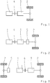
- Fig. 1 shows a drive train of a motor vehicle with an internal combustion engine 1, an output 2 and an automatic transmission 3 connected between the internal combustion engine 1 and the output 2.
- the automatic transmission comprises a large number of frictional shift elements, which can be designed as clutches or brakes.
- a separating clutch 4 is connected between the internal combustion engine 1 and the automatic transmission 3.
- Fig. 5 illustrates the implementation of a conventional train upshift on such a drive train, wherein in Fig. 5 A number of torque profiles are plotted over the time t, namely on the one hand a torque profile M VM for the torque provided by the internal combustion engine 1, a torque profile M AB for the torque applied to the output 2, and a torque profile M SE- CLOSE for switching on when the train is upshifted, frictional shift element of the manual transmission 3.
- the execution of the train upshift begins at the time t1, the frictional shifting element to be engaged being closed between the times t1 and t2 from the fully open state to the so-called landing point. Accordingly, the so-called engagement of the frictional shifting element to be engaged takes place between times t1 and t2, no significant moment being able to be transmitted during the application process thereof.
- the application or the application process of the switching element is also referred to as the free travel thereof, wherein in Fig. 5 the creation of the switching element to be switched on is exemplarily illustrated by a negative moment.
- the switching element to be switched on is completed.
- the shifting element of the automatic transmission 3 to be switched on takes over the load by further increasing the transmission capacity until the torque M VM provided by the internal combustion engine 2 can be transmitted. How Fig. 5 can be removed, the torque M AB acting on the output 2 decreases during the load transfer between the times t2 and t3. Between times t2 and t3, power loss occurs at the switching element to be switched on.
- the torque M VM provided by the internal combustion engine 1 is accordingly reduced at least between the times t1 and t2, it being provided according to an advantageous further development of the invention that the torque M VM provided by the internal combustion engine and thus the torque M AB acting on the output are reduced at the same time begins with the beginning of the application or application process of the switching element to be switched on, that is to say starting at time t1. Since there is already a reduced engine torque M VM at time t2, the power loss can be reduced.
- Fig. 8 illustrates the procedure known from the prior art for executing a train downshift, wherein in Fig. 8 The torque M VM provided by the internal combustion engine 1 and, on the other hand, the torque M SE-WEG transmitted by the shifting switching element of the automatic transmission 3 are shown over time t.
- Fig. 8 shows that in the execution of a conventional train downshift, which begins at time t1, beginning at time t1, the transmission capacity of the switching element that switches off is reduced, at time t2 the transmission capacity of the switching element that switches off corresponds to the torque M VM provided by internal combustion engine 1, starting from At time t2 the switching element that starts to slide starts to slide. At time t2, the switching phase of the train downshift therefore begins in which power loss occurs at the switching element switching off.
- the torque M VM provided by the internal combustion engine 1 is reduced, at least during the lowering or lowering process of the transmission capacity of the disconnecting, frictional shifting element, preferably until it slips,
- the torque M VM provided by the internal combustion engine 1 is reduced simultaneously with the beginning of the lowering of the transmission capacity of the disengaging, frictional shifting element, that is to say beginning with the time t1. This ensures that the torque M VM provided by the internal combustion engine 1 is already reduced at the point in time t2 at which the switching element begins to slide away, so that the power loss can also be reduced as a result.
- Fig. 2 the electrical machine 5 is connected between the automatic transmission 3 and the output 2, so that the electrical machine 5 can act permanently on the output 2 without power flow via the switching elements of the automatic transmission 3.
- the drive train of a hybrid vehicle Fig. 3 can the electric machine 5 act permanently on the output 2 without power flow via the shifting elements of the automatic transmission 3, in Fig. 3 the drive train is designed as a so-called axis hybrid, in which the electric machine 5 of the drive unit acts on a different axis of the output 2 than the internal combustion engine 1.
- the automatic transmission 3 is designed as a double clutch transmission with two partial transmissions 6 and 7, the internal combustion engine 1 being connectable to the input shaft of the partial transmission 6 via a power shift clutch 8 and to the input shaft of the partial transmission 7 via a further power shift clutch 9.
- the electric machine 5 of the drive unit is assigned to one of the two sub-transmissions, namely the sub-transmission 7, namely in such a way that the electric machine 5 is coupled to the input shaft of the sub-transmission 7 via a spur gear stage 10.
- the electrical machine 5 can act on the output 2 bypassing frictional power shift elements involved in the shift, namely bypassing the power shift elements of the gearbox 3 designed as power shift clutches 8 and 9.
- 6 and 7 illustrate the execution of a train upshift according to the invention on a drive train of a hybrid vehicle, the electric machine 5 of which does not act on the output 2 via the power shift elements of the automatic transmission 3 involved in the execution of the train upshift.
- a train upshift on the drivetrain Fig. 4 is carried out, namely a train upshift from an actual gear in the sub-transmission 6 to a target gear in the sub-transmission 7, in which case the engaging, frictional shifting element is the powershift clutch 9 and then the translation of the target gear in the sub-transmission 7 is smaller than the translation of the actual gear in Sub-gear 6 is.
- Fig. 6 shows a variant of the invention, in which the torque M VM provided by the internal combustion engine is reduced exclusively during application of the frictional shifting element to be engaged, that is to say between times t1 and t2.
- This reduction in the torque M VM provided by the internal combustion engine which brings about a reduction in the torque M AB effective at the output, preferably begins at the same time as the switching element to be switched on, in accordance with Fig. 6 Between the times t1 and t2, not only the torque M VM provided by the internal combustion engine 1 is reduced, but also the torque M EM provided by the electrical machine 5 is increased, so as to at least partially compensate for the reduction in the torque M EM provided by the internal combustion engine 1 .
- the increase in the torque M EM provided by the electrical machine 5 is limited by the maximum torque that can be provided by the same, the maximum torque that can be provided by the electrical machine 5 in particular by the temperature and the state of charge of an electrical energy store that interacts with the electrical machine 5 , is determined.
- the invention can be used to reduce the frictional torque and the power loss at the shifting element of the load upshift to be switched on, without the effective actuation and dimensioning of the electrical machine 5, compared to a conventional shifting, that the torque acting on the output 2 drops.
- the switching time required can be reduced, since the load transfer by the switching element to be switched on can take place faster between times t2 and t3, since the reduced torque of the internal combustion engine 1 is reached earlier by the switching element to be switched on.
- Fig. 7 shows a development of the method of Fig. 6 , in which the load transfer or load transfer from the internal combustion engine 1 to the electrical machine 5 is not ended at time t2, but rather only at time t3.
- the advantage of the variant of Fig. 7 compared to the variant of Fig. 6 is that in the variant of Fig. 7 the load transfer or load transfer from the internal combustion engine 1 to the electrical machine 5 takes place more slowly, so that any deviations in the actual torques of the electrical machine 5 and internal combustion engine 1 have a less pronounced effect on a circuit.
- Fig. 9 illustrates the execution of a train downshift according to the invention on a drive train of a hybrid vehicle, wherein Fig. 9 It can be seen that between times t1 and t2, that is to say while the transmission capacity of the disengaging, frictional shifting element is reduced until it slips at time t2, on the one hand the torque M VM provided by the internal combustion engine is reduced and on the other hand the torque provided by the electric machine 5 M EM is increased.
- This increase and reduction of the moments M VM and M EM takes place in Fig. 9 again at the same time as the beginning of the lowering or lowering process of the transmission capability of the switching element switching off and accordingly starting at time t1.
- the increase and reduction of the moments M VM and M EM ends at time t2, that is, when the frictional shifting element that starts to shift starts to slip.
- the at least partial shifting of the load from the internal combustion engine 1 to the electric machine 5 of the respective hybrid drive train is reversed, namely in such a way that when the shift to be carried out is completed, the load from the respective electric machine 5 to the respective one Internal combustion engine 1 is shifted back again by increasing the torque M VM provided by the internal combustion engine 1 and reducing the torque M EM provided by the electric machine 5 again.
- the torque provided by the internal combustion engine 1 can be completely reduced when executing a train upshift or a downshift according to the invention, a traction-interrupted shift being carried out in relation to the internal combustion engine 1 and drive torque and traction being provided on the output 2 exclusively by the respective electrical machine 5 becomes.
- the circuits according to the invention are only of importance for train shifts, namely for train upshifts and downshifts.
- the method according to the invention is not important for overrun circuits, since an internal combustion engine does not consume fuel when the overrun fuel cutoff is activated.
- upshifts and downshifts with reduced switching operation i.e. with a reduction in the torque M VM provided by the internal combustion engine or the torque M AB acting on the output, are only carried out if defined conditions are met individually or in combination with one another .
- a first such condition can be a defined driving situation of the motor vehicle.
- the reduced gearshift mode is only permitted when there is no cornering with increased lateral acceleration and / or there is no uphill driving of the motor vehicle.
- Another such condition can be the traffic situation in which the motor vehicle is operated.
- the reduced switching operation is only permitted if there is no entry into a roundabout and / or if there is no driving on an acceleration lane to engage the motor vehicle and / or if the motor vehicle is not being overtaken.
- Another condition can be an operating mode or driving mode of the motor vehicle. It can be provided that the reduced switching operation is only permitted in a so-called eco operating mode of the motor vehicle, which automatically or by actuating an operating element activates a fuel-saving operating mode of the motor vehicle.
- the reduced shift operation is only permitted if the target gear of the shift to be carried out is one of the last three gears, preferably one of the last two gears, of the automatic transmission.
- this variant of the invention is based on the knowledge that if there is a relatively small, lower target gear of a shift to be carried out, a lowered switching operation can be disruptive, since lower target gears generally concern driving situations in intersections, roundabouts or when turning.
- An advantageous further development of this aspect of the invention can provide for the driver to be automatically notified of the execution of a train upshift or downshift by building up an actuating counterforce on the accelerator pedal.
- an upcoming execution of a train upshift or downshift is announced via an actuator that is assigned to the accelerator pedal, namely by building up a counterpressure on the accelerator pedal.
- the reduced gearshift mode can then be permitted or not. It can thus be provided that when the driver reduces the accelerator pedal actuation relatively strongly in response to the counterpressure on the accelerator pedal, the reduced shifting operation for the train upshift or downshift to be carried out is permitted.
- the driver can thus influence the execution of a shift, namely the activation or deactivation of the reduced shift operation, by a corresponding accelerator pedal actuation and thus decide whether the loss of tractive force caused by the reduced shift operation or a reduction in the output torque M AB acting on the output 2 takes effect or not.
Landscapes
- Engineering & Computer Science (AREA)
- Mechanical Engineering (AREA)
- Chemical & Material Sciences (AREA)
- Combustion & Propulsion (AREA)
- Transportation (AREA)
- General Engineering & Computer Science (AREA)
- Automation & Control Theory (AREA)
- Control Of Transmission Device (AREA)
- Hybrid Electric Vehicles (AREA)
- Control Of Vehicle Engines Or Engines For Specific Uses (AREA)
Claims (14)
- Procédé pour faire fonctionner une chaîne cinématique d'un véhicule automobile, comprenant un groupe propulseur qui possède au moins un moteur à combustion interne et comprenant une boîte de vitesses automatique à éléments de changement de rapport entraînés par friction montée entre le groupe propulseur et un arbre de sortie,
c'est-à-dire en vue de réaliser le passage d'un rapport supérieur en traction avec la participation d'au moins un élément de changement de rapport entraîné par friction s'engageant de la boîte de vitesses automatique et d'au moins un élément de changement de rapport entraîné par friction se dégageant de la boîte de vitesses automatique, en vue de réaliser le passage d'un rapport supérieur en traction, le couple fourni par le moteur à combustion interne étant réduit au moins pendant l'opération d'application d'un élément de changement de rapport entraîné par friction s'engageant, et
en vue de réaliser le passage d'un rapport inférieur en traction, le couple fourni par le moteur à combustion interne étant réduit au moins pendant l'opération de diminution de la capacité de transmission d'un élément de changement de rapport entraîné par friction se dégageant,
caractérisé en ce que
le procédé est exclusivement mis en œuvre lorsqu'un rapport cible du passage d'un rapport supérieur en traction ou du passage d'un rapport inférieur en traction à réaliser est l'un des trois derniers rapports, de préférence l'un des deux derniers rapports de la boîte de vitesses automatique. - Procédé selon la revendication 1, caractérisé en ce qu'en vue de réaliser le passage d'un rapport supérieur en traction, le couple fourni par le moteur à combustion interne est réduit simultanément avec le début de l'opération d'application de l'élément de changement de rapport entraîné par friction s'engageant.
- Procédé selon la revendication 1 ou 2, caractérisé en ce que lorsqu'avec une chaîne cinématique d'un véhicule hybride, le groupe propulseur comprend une machine électrique en plus du moteur à combustion interne, et lorsque lors de la réalisation du passage d'un rapport supérieur en traction la machine électrique n'agit pas sur l'arbre de sortie par le biais des éléments de changement de rapport entraînés par friction de la boîte de vitesses automatique qui participent à la réalisation du passage d'un rapport supérieur, le couple fourni par le moteur à combustion interne est réduit et le couple fourni par la machine électrique est augmenté au moins pendant l'opération d'application de l'élément de changement de rapport entraîné par friction s'engageant afin de compenser au moins partiellement la réduction du couple fourni par le moteur à combustion interne.
- Procédé selon la revendication 3, caractérisé en ce que le transfert au moins partiel du couple fourni du moteur à combustion interne à la machine électrique commence simultanément avec le début de l'opération d'application de l'élément de changement de rapport entraîné par friction s'engageant.
- Procédé selon la revendication 4, caractérisé en ce que l'augmentation du couple fourni par la machine électrique en vue du transfert au moins partiel du couple fourni du moteur à combustion interne à la machine électrique prend fin lorsque l'opération d'application de l'élément de changement de rapport entraîné par friction s'engageant est terminée.
- Procédé selon la revendication 4, caractérisé en ce que l'augmentation du couple fourni par la machine électrique en vue du transfert au moins partiel du couple fourni du moteur à combustion interne à la machine électrique prend fin lorsque l'élément de changement de rapport entraîné par friction s'engageant est fermé au point qu'il transmet entièrement l'intégralité du couple fourni par le moteur à combustion interne.
- Procédé selon l'une des revendications 1 à 6, caractérisé en ce qu'en vue de réaliser le passage d'un rapport inférieur en traction, le couple fourni par le moteur à combustion interne est réduit simultanément avec le début de l'opération de diminution de la capacité de transmission de l'élément de changement de rapport entraîné par friction se dégageant.
- Procédé selon l'une des revendications 1 à 7, caractérisé en ce que lorsqu'avec une chaîne cinématique d'un véhicule hybride, le groupe propulseur comprend une machine électrique en plus du moteur à combustion interne, et lorsque lors de la réalisation du passage d'un rapport inférieur en traction la machine électrique n'agit pas sur l'arbre de sortie par le biais des éléments de changement de rapport entraînés par friction de la boîte de vitesses automatique qui participent à la réalisation du passage d'un rapport supérieur, le couple fourni par le moteur à combustion interne est réduit et le couple fourni par la machine électrique est augmenté au moins pendant l'opération de diminution de la capacité de transmission de l'élément de changement de rapport entraîné par friction se dégageant afin de compenser au moins partiellement la réduction du couple fourni par le moteur à combustion interne.
- Procédé selon la revendication 8, caractérisé en ce que le transfert au moins partiel du couple fourni du moteur à combustion interne à la machine électrique commence simultanément avec le début de l'opération de diminution de la capacité de transmission de l'élément de changement de rapport entraîné par friction se dégageant.
- Procédé selon l'une des revendications 1 à 9, caractérisé en ce qu'à la fin du changement de rapport à effectuer, le couple fourni par le moteur à combustion interne est de nouveau augmenté et dans le cas d'une chaîne cinématique d'un véhicule hybride, en plus de cela le couple fourni par la machine électrique est de nouveau réduit.
- Procédé selon l'une des revendications 1 à 10, caractérisé en ce que le procédé est uniquement mis en œuvre lorsque la situation de conduite en présence n'est pas un trajet en côte et/ou un trajet en virage.
- Procédé selon l'une des revendications 1 à 10, caractérisé en ce que le procédé est uniquement mis en œuvre lorsque la situation de trafic en présence n'est pas une entrée dans un rond-point et/ou une manœuvre de dépassement.
- Procédé selon l'une des revendications 1 à 12, caractérisé en ce que celui-ci est exclusivement mis en œuvre lorsqu'un actionnement de pédale d'accélérateur côté conducteur est inférieur à une valeur limite.
- Procédé selon la revendication 13, caractérisé en ce que la réalisation du passage d'un rapport supérieur en traction ou du passage d'un rapport inférieur en traction est annoncée automatiquement au conducteur par l'établissement d'une force antagoniste d'actionnement au niveau de la pédale d'accélérateur et en ce que lorsque l'actionnement de la pédale d'accélérateur du côté du conducteur est ensuite fortement diminué, le couple fourni par le moteur à combustion interne est réduit en vue de réaliser le changement de rapport, alors qu'en revanche, si l'actionnement de la pédale d'accélérateur du côté du conducteur est ensuite diminué relativement faiblement ou pas du tout, le couple fourni par le moteur à combustion interne n'est pas réduit en vue de réaliser le changement de rapport.
Applications Claiming Priority (1)
| Application Number | Priority Date | Filing Date | Title |
|---|---|---|---|
| DE102010061823.3A DE102010061823B4 (de) | 2010-11-24 | 2010-11-24 | Verfahren zum Betreiben eines Antriebsstrangs |
Publications (3)
| Publication Number | Publication Date |
|---|---|
| EP2457794A2 EP2457794A2 (fr) | 2012-05-30 |
| EP2457794A3 EP2457794A3 (fr) | 2014-01-22 |
| EP2457794B1 true EP2457794B1 (fr) | 2020-07-15 |
Family
ID=45098847
Family Applications (1)
| Application Number | Title | Priority Date | Filing Date |
|---|---|---|---|
| EP11185393.3A Active EP2457794B1 (fr) | 2010-11-24 | 2011-10-17 | Procédé destiné au fonctionnement d'une chaîne cinématique |
Country Status (3)
| Country | Link |
|---|---|
| US (2) | US8808137B2 (fr) |
| EP (1) | EP2457794B1 (fr) |
| DE (1) | DE102010061823B4 (fr) |
Families Citing this family (15)
| Publication number | Priority date | Publication date | Assignee | Title |
|---|---|---|---|---|
| DE102008040692A1 (de) * | 2008-07-24 | 2010-01-28 | Robert Bosch Gmbh | Verfahren und Vorrichtung zum Anfahren eines Hybridfahrzeuges |
| DE102012211920A1 (de) * | 2012-07-09 | 2014-01-09 | Bayerische Motoren Werke Aktiengesellschaft | Verfahren zum Betrieb eines Hybridfahrzeuges |
| US8795131B2 (en) * | 2012-11-28 | 2014-08-05 | Ford Global Technologies, Llc | Method and apparatus for reducing torque during a transmission upshift for a hybrid vehicle |
| DE102013010013A1 (de) * | 2013-06-14 | 2014-12-18 | Volkswagen Aktiengesellschaft | Verfahren und Vorrichtung zur Steuerung eines Schaltgetriebes |
| DE102013214762A1 (de) * | 2013-07-29 | 2015-01-29 | Zf Friedrichshafen Ag | Verfahren zur Regelung eines automatisierten Kraftfahrzeuggetriebes |
| US9260000B2 (en) | 2013-10-23 | 2016-02-16 | Ford Global Technologies, Llc | Synchronous speed disconnect of a generator for a hybrid electric vehicle |
| JP6447154B2 (ja) * | 2015-01-15 | 2019-01-09 | トヨタ自動車株式会社 | 車両の駆動装置 |
| DE102015214751A1 (de) * | 2015-08-03 | 2017-02-09 | Robert Bosch Gmbh | Antriebsvorrichtung für ein Kraftfahrzeug und Verfahren zum Betreiben einer Antriebsvorrichtung für ein Kraftfahrzeug |
| KR101714192B1 (ko) * | 2015-08-12 | 2017-03-08 | 현대자동차주식회사 | 클러치 버스트 방지 방법 |
| DE102015219340A1 (de) * | 2015-10-07 | 2017-04-13 | Robert Bosch Gmbh | Verfahren und Vorrichtung zum Betreiben einer Antriebsvorrichtung, Antriebsvorrichtung |
| US9440640B1 (en) * | 2015-10-16 | 2016-09-13 | Borgwarner Inc. | Gear change torque fill strategy |
| US10336311B2 (en) | 2017-06-13 | 2019-07-02 | Cnh Industrial America Llc | System and method for controlling the speed of a work vehicle during downhill operation |
| DE102017214396A1 (de) * | 2017-08-18 | 2019-02-21 | Bayerische Motoren Werke Aktiengesellschaft | Hybridantriebsgetriebeeinheit sowie Verfahren zum Betreiben eines Fahrzeugs mit Hybridantrieb |
| DE102019003780B3 (de) * | 2019-05-29 | 2020-07-02 | Daimler Ag | Hybridantriebsystem |
| KR102791264B1 (ko) * | 2020-06-12 | 2025-04-09 | 현대자동차주식회사 | 하이브리드 차량 및 그의 모터 토크 보상 방법 |
Family Cites Families (27)
| Publication number | Priority date | Publication date | Assignee | Title |
|---|---|---|---|---|
| US2673474A (en) * | 1950-09-13 | 1954-03-30 | Carter Carburetor Corp | Transmission control mechanism |
| DE2842389C2 (de) * | 1978-09-29 | 1984-04-12 | Robert Bosch Gmbh, 7000 Stuttgart | Vorrichtung zur Einstellung des Drehmomentes einer Brennkraftmaschine |
| DE3512604A1 (de) * | 1985-04-06 | 1986-10-16 | Daimler-Benz Ag, 7000 Stuttgart | Vorrichtung zur verminderung des motordrehmomentes bei einer umschaltung eines einem verbrennungsmotor nachgeschalteten gangwechselgetriebes |
| JP2764749B2 (ja) * | 1989-11-16 | 1998-06-11 | トヨタ自動車株式会社 | 自動変速機の変速制御装置 |
| JP2949156B2 (ja) * | 1990-03-26 | 1999-09-13 | トヨタ自動車株式会社 | 自動変速機のダウンシフト制御装置 |
| DE4333899A1 (de) * | 1993-10-05 | 1995-07-13 | Bosch Gmbh Robert | Verfahren zur Steuerung des Abtriebsmoments eines automatischen Schaltgetriebes |
| DE19544516C3 (de) * | 1995-11-29 | 2003-12-11 | Siemens Ag | Steuereinrichtung für ein automatisches Kraftfahrzeuggetriebe |
| DE19850549A1 (de) | 1998-11-03 | 2000-05-04 | Bosch Gmbh Robert | Getriebe für ein Kraftfahrzeug, insbesondere Doppelkupplungs-Schaltgetriebe, und Verfahren zum Betreiben des Getriebes |
| DE10043420B4 (de) * | 1999-10-06 | 2015-11-12 | Schaeffler Technologies AG & Co. KG | Verfahren zur Steuerung eines Gangwechselvorgangs |
| DE10101597A1 (de) * | 2000-02-15 | 2001-08-16 | Luk Lamellen & Kupplungsbau | Getriebe |
| US6941830B2 (en) * | 2000-03-10 | 2005-09-13 | Hitachi, Ltd. | Automatic transmission, dynamo-electric machine, and car |
| DE10165097B3 (de) * | 2000-07-18 | 2015-07-23 | Schaeffler Technologies AG & Co. KG | Doppelkupplungsgetriebe |
| DE10160308A1 (de) * | 2001-01-12 | 2002-07-18 | Zf Sachs Ag | Verfahren zum Betrieb eines eine Mehrfach-Kupplungseinrichtung und ein Lastschaltgetriebe aufweisenden Antriebsstrangs und derartiger Antriebsstrang mit entprechender Steuereinheit |
| JP4286149B2 (ja) * | 2002-03-07 | 2009-06-24 | ルーク ラメレン ウント クツプルングスバウ ベタイリグングス コマンディートゲゼルシャフト | ツインクラッチ式トランスミッションにおけるギアシフト実施方法 |
| AU2003227013A1 (en) * | 2002-03-07 | 2003-09-16 | Luk Lamellen Und Kupplungsbau Beteiligungs Kg | Method for carrying out gear shifting in a twin-clutch gearbox |
| JP4000967B2 (ja) * | 2002-09-13 | 2007-10-31 | トヨタ自動車株式会社 | ダウンシフト時のトルクダウン制御装置 |
| JP3872783B2 (ja) * | 2003-09-03 | 2007-01-24 | 日産自動車株式会社 | 自動変速機の変速ショック軽減装置 |
| JP4038460B2 (ja) * | 2003-09-04 | 2008-01-23 | 株式会社日立製作所 | アクティブシフト変速機,変速機制御装置、および自動車 |
| KR100579259B1 (ko) * | 2003-12-22 | 2006-05-11 | 현대자동차주식회사 | 자동변속기의 변속 제어방법 및 장치 |
| JP2006132562A (ja) * | 2004-11-02 | 2006-05-25 | Nissan Motor Co Ltd | ツインクラッチ式マニュアルトランスミッションのクラッチ偏摩耗時変速制御装置 |
| US7223201B2 (en) * | 2004-12-28 | 2007-05-29 | Ford Global Technologies, Llc | Control of power-on downshifts in a multiple-ratio powertrain for a hybrid vehicle |
| DE102006003711A1 (de) * | 2006-01-26 | 2007-08-02 | Zf Friedrichshafen Ag | Verfahren zur Steuerung eines Kraftfahrzeug-Antriebsstrangs |
| JP4745284B2 (ja) * | 2006-08-28 | 2011-08-10 | 日産自動車株式会社 | パワートレーンの変速ショック軽減装置 |
| CN101516708B (zh) * | 2006-09-15 | 2012-07-04 | 舍弗勒技术股份两合公司 | 用来运行用于机动车的混合动力总成系统的方法 |
| DE102008000343A1 (de) * | 2008-02-19 | 2009-08-20 | Zf Friedrichshafen Ag | Verfahren zum Betreiben eines Antriebsstranges eines Fahrzeuges |
| US8079936B2 (en) * | 2009-04-09 | 2011-12-20 | Ford Global Technologies, Llc | Gear shift control of a dual clutch transmission |
| DE102009020651A1 (de) * | 2009-05-08 | 2010-11-18 | Daimler Ag | Getriebevorrichtung |
-
2010
- 2010-11-24 DE DE102010061823.3A patent/DE102010061823B4/de active Active
-
2011
- 2011-10-17 EP EP11185393.3A patent/EP2457794B1/fr active Active
- 2011-11-04 US US13/289,173 patent/US8808137B2/en active Active
-
2014
- 2014-07-23 US US14/338,389 patent/US9399458B2/en not_active Expired - Fee Related
Non-Patent Citations (1)
| Title |
|---|
| None * |
Also Published As
| Publication number | Publication date |
|---|---|
| DE102010061823A1 (de) | 2012-05-24 |
| US9399458B2 (en) | 2016-07-26 |
| DE102010061823B4 (de) | 2020-02-13 |
| EP2457794A2 (fr) | 2012-05-30 |
| US20120129649A1 (en) | 2012-05-24 |
| US20140335996A1 (en) | 2014-11-13 |
| EP2457794A3 (fr) | 2014-01-22 |
| US8808137B2 (en) | 2014-08-19 |
Similar Documents
| Publication | Publication Date | Title |
|---|---|---|
| DE102010061823B4 (de) | Verfahren zum Betreiben eines Antriebsstrangs | |
| EP2524156B1 (fr) | Procédé pour faire fonctionner un dispositif de transmission comprenant plusieurs éléments de changement de vitesse à friction et au moins un élément de changement de vitesse à complémentarité de forme | |
| EP0827861B1 (fr) | Procédé de changement de vitesses d'une boîte de vitesses à double embrayage et transmission à double embrayage | |
| EP2524155B1 (fr) | Procédé pour faire fonctionner une chaîne cinématique de véhicule à moteur comprenant un moteur d'entraînement et un mécanisme de transmission comportant plusieurs éléments de changement de vitesse | |
| EP2765338B1 (fr) | Procédé destiné au fonctionnement d'une chaîne cinématique hybridée de boîte de vitesses à double embrayage | |
| DE102012220171A1 (de) | Schaltsteuerung bei Absichtsänderung | |
| DE102007038771A1 (de) | Verfahren zum Starten des Verbrennungsmotors während einer Lastschaltung bei parallelen Hybridfahrzeugen | |
| DE102011089467A1 (de) | Hybridantrieb eines Kraftfahrzeugs und Verfahren zum Betreiben desselben | |
| DE102010061827A1 (de) | Antriebsstrang und Verfahren zum Betreiben desselben | |
| EP2794317B1 (fr) | Entraînement hybride d'un véhicule automobile et son procédé de fonctionnement | |
| DE102014016932A1 (de) | Verfahren zum Schalten eines Gruppengetriebes eines Kraftwagens | |
| WO2017060010A1 (fr) | Procédé et dispositif pour faire fonctionner un système de propulsion, système de propulsion | |
| DE19937716C1 (de) | Doppelkupplungs-Mehrganggetriebe | |
| DE19924501A1 (de) | Lastschaltbares Stufenwechselgetriebe | |
| DE19908602A1 (de) | Automatisierter Antriebsstrang für ein Kraftfahrzeug und Verfahren zum Steuern eines Antriebsstranges | |
| DE102009000252A1 (de) | Verfahren zum Betreiben eines Fahrzeugantriebsstranges | |
| EP2524157B1 (fr) | Procédé pour faire fonctionner une chaîne cinématique de véhicule à moteur comprenant un moteur à combustion interne | |
| DE102022102678A1 (de) | Steuervorrichtung und verfahren zur steuerung eines antriebsstrangs eines fahrzeugs während das fahrzeug in bewegung ist | |
| DE102008001199B4 (de) | Verfahren zum Betreiben eines Doppelkupplungsgetriebes | |
| DE102019216464A1 (de) | Automatisches Schaltgetriebe für Kraftfahrzeuge | |
| WO2005008103A1 (fr) | Procede de commutation d'une boite de vitesses a double embrayage d'automobile | |
| DE10238128A1 (de) | Verfahren zum Steuern eines Antriebsstranges eines Fahrzeugs | |
| DE10238127A1 (de) | Verfahren zum Steuern eines Antriebsstranges eines Fahrzeugs | |
| DE102017203108A1 (de) | Verfahren zur Steuerung eines Automatikgetriebes | |
| DE102021213682B3 (de) | Verfahren und Steuergerät zum Betreiben eines Antriebsstrangs eines Kraftfahrzeugs |
Legal Events
| Date | Code | Title | Description |
|---|---|---|---|
| PUAI | Public reference made under article 153(3) epc to a published international application that has entered the european phase |
Free format text: ORIGINAL CODE: 0009012 |
|
| AK | Designated contracting states |
Kind code of ref document: A2 Designated state(s): AL AT BE BG CH CY CZ DE DK EE ES FI FR GB GR HR HU IE IS IT LI LT LU LV MC MK MT NL NO PL PT RO RS SE SI SK SM TR |
|
| AX | Request for extension of the european patent |
Extension state: BA ME |
|
| RIC1 | Information provided on ipc code assigned before grant |
Ipc: B60W 30/18 20120101AFI20131025BHEP Ipc: F16H 63/50 20060101ALI20131025BHEP |
|
| PUAL | Search report despatched |
Free format text: ORIGINAL CODE: 0009013 |
|
| AK | Designated contracting states |
Kind code of ref document: A3 Designated state(s): AL AT BE BG CH CY CZ DE DK EE ES FI FR GB GR HR HU IE IS IT LI LT LU LV MC MK MT NL NO PL PT RO RS SE SI SK SM TR |
|
| AX | Request for extension of the european patent |
Extension state: BA ME |
|
| RIC1 | Information provided on ipc code assigned before grant |
Ipc: F16H 63/50 20060101ALI20131217BHEP Ipc: B60W 30/18 20120101AFI20131217BHEP |
|
| 17P | Request for examination filed |
Effective date: 20140718 |
|
| STAA | Information on the status of an ep patent application or granted ep patent |
Free format text: STATUS: EXAMINATION IS IN PROGRESS |
|
| 17Q | First examination report despatched |
Effective date: 20190226 |
|
| GRAP | Despatch of communication of intention to grant a patent |
Free format text: ORIGINAL CODE: EPIDOSNIGR1 |
|
| STAA | Information on the status of an ep patent application or granted ep patent |
Free format text: STATUS: GRANT OF PATENT IS INTENDED |
|
| INTG | Intention to grant announced |
Effective date: 20200131 |
|
| GRAS | Grant fee paid |
Free format text: ORIGINAL CODE: EPIDOSNIGR3 |
|
| GRAA | (expected) grant |
Free format text: ORIGINAL CODE: 0009210 |
|
| STAA | Information on the status of an ep patent application or granted ep patent |
Free format text: STATUS: THE PATENT HAS BEEN GRANTED |
|
| AK | Designated contracting states |
Kind code of ref document: B1 Designated state(s): AL AT BE BG CH CY CZ DE DK EE ES FI FR GB GR HR HU IE IS IT LI LT LU LV MC MK MT NL NO PL PT RO RS SE SI SK SM TR |
|
| REG | Reference to a national code |
Ref country code: CH Ref legal event code: EP Ref country code: GB Ref legal event code: FG4D Free format text: NOT ENGLISH |
|
| REG | Reference to a national code |
Ref country code: IE Ref legal event code: FG4D Free format text: LANGUAGE OF EP DOCUMENT: GERMAN |
|
| REG | Reference to a national code |
Ref country code: DE Ref legal event code: R096 Ref document number: 502011016796 Country of ref document: DE |
|
| REG | Reference to a national code |
Ref country code: AT Ref legal event code: REF Ref document number: 1290706 Country of ref document: AT Kind code of ref document: T Effective date: 20200815 |
|
| REG | Reference to a national code |
Ref country code: LT Ref legal event code: MG4D |
|
| REG | Reference to a national code |
Ref country code: NL Ref legal event code: MP Effective date: 20200715 |
|
| PG25 | Lapsed in a contracting state [announced via postgrant information from national office to epo] |
Ref country code: BG Free format text: LAPSE BECAUSE OF FAILURE TO SUBMIT A TRANSLATION OF THE DESCRIPTION OR TO PAY THE FEE WITHIN THE PRESCRIBED TIME-LIMIT Effective date: 20201015 Ref country code: NO Free format text: LAPSE BECAUSE OF FAILURE TO SUBMIT A TRANSLATION OF THE DESCRIPTION OR TO PAY THE FEE WITHIN THE PRESCRIBED TIME-LIMIT Effective date: 20201015 Ref country code: SE Free format text: LAPSE BECAUSE OF FAILURE TO SUBMIT A TRANSLATION OF THE DESCRIPTION OR TO PAY THE FEE WITHIN THE PRESCRIBED TIME-LIMIT Effective date: 20200715 Ref country code: HR Free format text: LAPSE BECAUSE OF FAILURE TO SUBMIT A TRANSLATION OF THE DESCRIPTION OR TO PAY THE FEE WITHIN THE PRESCRIBED TIME-LIMIT Effective date: 20200715 Ref country code: PT Free format text: LAPSE BECAUSE OF FAILURE TO SUBMIT A TRANSLATION OF THE DESCRIPTION OR TO PAY THE FEE WITHIN THE PRESCRIBED TIME-LIMIT Effective date: 20201116 Ref country code: ES Free format text: LAPSE BECAUSE OF FAILURE TO SUBMIT A TRANSLATION OF THE DESCRIPTION OR TO PAY THE FEE WITHIN THE PRESCRIBED TIME-LIMIT Effective date: 20200715 Ref country code: LT Free format text: LAPSE BECAUSE OF FAILURE TO SUBMIT A TRANSLATION OF THE DESCRIPTION OR TO PAY THE FEE WITHIN THE PRESCRIBED TIME-LIMIT Effective date: 20200715 Ref country code: GR Free format text: LAPSE BECAUSE OF FAILURE TO SUBMIT A TRANSLATION OF THE DESCRIPTION OR TO PAY THE FEE WITHIN THE PRESCRIBED TIME-LIMIT Effective date: 20201016 Ref country code: FI Free format text: LAPSE BECAUSE OF FAILURE TO SUBMIT A TRANSLATION OF THE DESCRIPTION OR TO PAY THE FEE WITHIN THE PRESCRIBED TIME-LIMIT Effective date: 20200715 |
|
| PG25 | Lapsed in a contracting state [announced via postgrant information from national office to epo] |
Ref country code: LV Free format text: LAPSE BECAUSE OF FAILURE TO SUBMIT A TRANSLATION OF THE DESCRIPTION OR TO PAY THE FEE WITHIN THE PRESCRIBED TIME-LIMIT Effective date: 20200715 Ref country code: RS Free format text: LAPSE BECAUSE OF FAILURE TO SUBMIT A TRANSLATION OF THE DESCRIPTION OR TO PAY THE FEE WITHIN THE PRESCRIBED TIME-LIMIT Effective date: 20200715 Ref country code: PL Free format text: LAPSE BECAUSE OF FAILURE TO SUBMIT A TRANSLATION OF THE DESCRIPTION OR TO PAY THE FEE WITHIN THE PRESCRIBED TIME-LIMIT Effective date: 20200715 Ref country code: IS Free format text: LAPSE BECAUSE OF FAILURE TO SUBMIT A TRANSLATION OF THE DESCRIPTION OR TO PAY THE FEE WITHIN THE PRESCRIBED TIME-LIMIT Effective date: 20201115 |
|
| PG25 | Lapsed in a contracting state [announced via postgrant information from national office to epo] |
Ref country code: NL Free format text: LAPSE BECAUSE OF FAILURE TO SUBMIT A TRANSLATION OF THE DESCRIPTION OR TO PAY THE FEE WITHIN THE PRESCRIBED TIME-LIMIT Effective date: 20200715 |
|
| REG | Reference to a national code |
Ref country code: DE Ref legal event code: R097 Ref document number: 502011016796 Country of ref document: DE |
|
| PG25 | Lapsed in a contracting state [announced via postgrant information from national office to epo] |
Ref country code: SM Free format text: LAPSE BECAUSE OF FAILURE TO SUBMIT A TRANSLATION OF THE DESCRIPTION OR TO PAY THE FEE WITHIN THE PRESCRIBED TIME-LIMIT Effective date: 20200715 Ref country code: RO Free format text: LAPSE BECAUSE OF FAILURE TO SUBMIT A TRANSLATION OF THE DESCRIPTION OR TO PAY THE FEE WITHIN THE PRESCRIBED TIME-LIMIT Effective date: 20200715 Ref country code: DK Free format text: LAPSE BECAUSE OF FAILURE TO SUBMIT A TRANSLATION OF THE DESCRIPTION OR TO PAY THE FEE WITHIN THE PRESCRIBED TIME-LIMIT Effective date: 20200715 Ref country code: CZ Free format text: LAPSE BECAUSE OF FAILURE TO SUBMIT A TRANSLATION OF THE DESCRIPTION OR TO PAY THE FEE WITHIN THE PRESCRIBED TIME-LIMIT Effective date: 20200715 Ref country code: EE Free format text: LAPSE BECAUSE OF FAILURE TO SUBMIT A TRANSLATION OF THE DESCRIPTION OR TO PAY THE FEE WITHIN THE PRESCRIBED TIME-LIMIT Effective date: 20200715 Ref country code: IT Free format text: LAPSE BECAUSE OF FAILURE TO SUBMIT A TRANSLATION OF THE DESCRIPTION OR TO PAY THE FEE WITHIN THE PRESCRIBED TIME-LIMIT Effective date: 20200715 |
|
| PLBE | No opposition filed within time limit |
Free format text: ORIGINAL CODE: 0009261 |
|
| STAA | Information on the status of an ep patent application or granted ep patent |
Free format text: STATUS: NO OPPOSITION FILED WITHIN TIME LIMIT |
|
| PG25 | Lapsed in a contracting state [announced via postgrant information from national office to epo] |
Ref country code: AL Free format text: LAPSE BECAUSE OF FAILURE TO SUBMIT A TRANSLATION OF THE DESCRIPTION OR TO PAY THE FEE WITHIN THE PRESCRIBED TIME-LIMIT Effective date: 20200715 |
|
| REG | Reference to a national code |
Ref country code: CH Ref legal event code: PL |
|
| 26N | No opposition filed |
Effective date: 20210416 |
|
| GBPC | Gb: european patent ceased through non-payment of renewal fee |
Effective date: 20201017 |
|
| PG25 | Lapsed in a contracting state [announced via postgrant information from national office to epo] |
Ref country code: MC Free format text: LAPSE BECAUSE OF FAILURE TO SUBMIT A TRANSLATION OF THE DESCRIPTION OR TO PAY THE FEE WITHIN THE PRESCRIBED TIME-LIMIT Effective date: 20200715 Ref country code: LU Free format text: LAPSE BECAUSE OF NON-PAYMENT OF DUE FEES Effective date: 20201017 Ref country code: SK Free format text: LAPSE BECAUSE OF FAILURE TO SUBMIT A TRANSLATION OF THE DESCRIPTION OR TO PAY THE FEE WITHIN THE PRESCRIBED TIME-LIMIT Effective date: 20200715 |
|
| REG | Reference to a national code |
Ref country code: BE Ref legal event code: MM Effective date: 20201031 |
|
| PG25 | Lapsed in a contracting state [announced via postgrant information from national office to epo] |
Ref country code: FR Free format text: LAPSE BECAUSE OF NON-PAYMENT OF DUE FEES Effective date: 20201031 |
|
| PG25 | Lapsed in a contracting state [announced via postgrant information from national office to epo] |
Ref country code: CH Free format text: LAPSE BECAUSE OF NON-PAYMENT OF DUE FEES Effective date: 20201031 Ref country code: BE Free format text: LAPSE BECAUSE OF NON-PAYMENT OF DUE FEES Effective date: 20201031 Ref country code: SI Free format text: LAPSE BECAUSE OF FAILURE TO SUBMIT A TRANSLATION OF THE DESCRIPTION OR TO PAY THE FEE WITHIN THE PRESCRIBED TIME-LIMIT Effective date: 20200715 Ref country code: GB Free format text: LAPSE BECAUSE OF NON-PAYMENT OF DUE FEES Effective date: 20201017 Ref country code: LI Free format text: LAPSE BECAUSE OF NON-PAYMENT OF DUE FEES Effective date: 20201031 |
|
| PG25 | Lapsed in a contracting state [announced via postgrant information from national office to epo] |
Ref country code: IE Free format text: LAPSE BECAUSE OF NON-PAYMENT OF DUE FEES Effective date: 20201017 |
|
| REG | Reference to a national code |
Ref country code: AT Ref legal event code: MM01 Ref document number: 1290706 Country of ref document: AT Kind code of ref document: T Effective date: 20201017 |
|
| PG25 | Lapsed in a contracting state [announced via postgrant information from national office to epo] |
Ref country code: AT Free format text: LAPSE BECAUSE OF NON-PAYMENT OF DUE FEES Effective date: 20201017 |
|
| PG25 | Lapsed in a contracting state [announced via postgrant information from national office to epo] |
Ref country code: TR Free format text: LAPSE BECAUSE OF FAILURE TO SUBMIT A TRANSLATION OF THE DESCRIPTION OR TO PAY THE FEE WITHIN THE PRESCRIBED TIME-LIMIT Effective date: 20200715 Ref country code: MT Free format text: LAPSE BECAUSE OF FAILURE TO SUBMIT A TRANSLATION OF THE DESCRIPTION OR TO PAY THE FEE WITHIN THE PRESCRIBED TIME-LIMIT Effective date: 20200715 Ref country code: CY Free format text: LAPSE BECAUSE OF FAILURE TO SUBMIT A TRANSLATION OF THE DESCRIPTION OR TO PAY THE FEE WITHIN THE PRESCRIBED TIME-LIMIT Effective date: 20200715 |
|
| PG25 | Lapsed in a contracting state [announced via postgrant information from national office to epo] |
Ref country code: MK Free format text: LAPSE BECAUSE OF FAILURE TO SUBMIT A TRANSLATION OF THE DESCRIPTION OR TO PAY THE FEE WITHIN THE PRESCRIBED TIME-LIMIT Effective date: 20200715 |
|
| P01 | Opt-out of the competence of the unified patent court (upc) registered |
Effective date: 20230528 |
|
| PGFP | Annual fee paid to national office [announced via postgrant information from national office to epo] |
Ref country code: DE Payment date: 20250902 Year of fee payment: 15 |