EP2457795A1 - Kupplungsvorrichtung - Google Patents
Kupplungsvorrichtung Download PDFInfo
- Publication number
- EP2457795A1 EP2457795A1 EP10015090A EP10015090A EP2457795A1 EP 2457795 A1 EP2457795 A1 EP 2457795A1 EP 10015090 A EP10015090 A EP 10015090A EP 10015090 A EP10015090 A EP 10015090A EP 2457795 A1 EP2457795 A1 EP 2457795A1
- Authority
- EP
- European Patent Office
- Prior art keywords
- coupling
- coupling device
- toothed
- rubber
- elastic
- Prior art date
- Legal status (The legal status is an assumption and is not a legal conclusion. Google has not performed a legal analysis and makes no representation as to the accuracy of the status listed.)
- Granted
Links
Images


Classifications
-
- F—MECHANICAL ENGINEERING; LIGHTING; HEATING; WEAPONS; BLASTING
- F16—ENGINEERING ELEMENTS AND UNITS; GENERAL MEASURES FOR PRODUCING AND MAINTAINING EFFECTIVE FUNCTIONING OF MACHINES OR INSTALLATIONS; THERMAL INSULATION IN GENERAL
- F16D—COUPLINGS FOR TRANSMITTING ROTATION; CLUTCHES; BRAKES
- F16D3/00—Yielding couplings, i.e. with means permitting movement between the connected parts during the drive
- F16D3/50—Yielding couplings, i.e. with means permitting movement between the connected parts during the drive with the coupling parts connected by one or more intermediate members
- F16D3/60—Yielding couplings, i.e. with means permitting movement between the connected parts during the drive with the coupling parts connected by one or more intermediate members comprising pushing or pulling links attached to both parts
- F16D3/62—Yielding couplings, i.e. with means permitting movement between the connected parts during the drive with the coupling parts connected by one or more intermediate members comprising pushing or pulling links attached to both parts the links or their attachments being elastic
-
- F—MECHANICAL ENGINEERING; LIGHTING; HEATING; WEAPONS; BLASTING
- F16—ENGINEERING ELEMENTS AND UNITS; GENERAL MEASURES FOR PRODUCING AND MAINTAINING EFFECTIVE FUNCTIONING OF MACHINES OR INSTALLATIONS; THERMAL INSULATION IN GENERAL
- F16D—COUPLINGS FOR TRANSMITTING ROTATION; CLUTCHES; BRAKES
- F16D3/00—Yielding couplings, i.e. with means permitting movement between the connected parts during the drive
- F16D3/16—Universal joints in which flexibility is produced by means of pivots or sliding or rolling connecting parts
- F16D3/18—Universal joints in which flexibility is produced by means of pivots or sliding or rolling connecting parts the coupling parts (1) having slidably-interengaging teeth
- F16D3/185—Universal joints in which flexibility is produced by means of pivots or sliding or rolling connecting parts the coupling parts (1) having slidably-interengaging teeth radial teeth connecting concentric inner and outer coupling parts
Definitions
- the invention relates to a coupling device for connecting a driving and a driven machine part.
- Such machine parts are, for example, shafts, hubs or flanges.
- the coupling device comprises a drive-side and a driven-side coupling element, which are interconnected by an intermediate shaft.
- Such coupling devices are quite torsionally stiff and at the same time allow compensation of radial and axial offset between two rotating machine parts to be connected.
- a coupling for connecting a driving and a driven machine part which comprises at the ends of an intermediate shaft hinge lever couplings, each having at least three identical toggle levers.
- the articulated levers rest on the one hand on the intermediate shaft and on the other hand on the machine parts to be connected via elastic joints arranged at their ends.
- the elastic joints have axes which are each aligned perpendicular to an axis of the intermediate shaft or on axes of the machine parts to be connected or on an axis of the intermediate shaft or the axes of the machine parts to be connected and laid parallel to the articulated levers axial plane.
- a drive unit for rail vehicles which comprises a suspended on a vehicle frame or chassis electric motor, a transmission and a gimbal-acting clutch system.
- the clutch system is arranged between a wheelset shaft and the transmission.
- a first part of the coupling system is integrated in the form of a gear coupling in an output gear of the transmission and in the lubricating oil circuit.
- a driven-side second part of the clutch system is provided between the gearbox and wheelset.
- the second part of the coupling system for example, a rubber-elastic coupling.
- the present invention has for its object to provide a coupling device which has a high torsional stiffness, allows compensation of radial and axial offset between two rotating machine parts to be connected and can prevent electrical current flow.
- the coupling device according to the invention for connecting a driving machine part with a driven machine part comprises a arranged on a first drive or driven side end portion of the coupling device rubber-elastic coupling.
- a toothed clutch is arranged at a second output or drive-side end portion of the coupling device.
- an intermediate shaft which connects the rubber-elastic coupling with the toothed coupling is provided.
- the toothed coupling and the rubber-elastic coupling have such matched restoring forces that the coupling device has both a central run and an axial offset compensation in the case of a radial displacement.
- the coupling device according to the invention enables an effective compensation of radial and axial offset between two rotating machine parts to be connected and an inhibition of a current flow caused for example by electrical machines via a drive train comprising the coupling device.
- the restoring forces can also be coordinated with one another in such a way that the coupling device always runs centrically in normal operation and can compensate for an axial offset at a predetermined starting torque.
- the rubber-elastic coupling and the toothed coupling are coordinated so that the resulting radial and axial restoring forces are minimized.
- the rubber-elastic coupling may comprise, for example, a toggle coupling, a tab coupling, a wedge-pack coupling, a steel disc coupling with a rubber-elastic intermediate piece, a bolt coupling or a dog clutch.
- Such couplings have good electrical insulating properties and a high torsional rigidity.
- the toothed coupling on a curved toothing is integrated in a transmission hollow shaft.
- the gear coupling may be mounted in front of the gear hollow shaft.
- the gear coupling according to another embodiment of the present invention comprises an inner and an outer coupling element
- the outer coupling element can form an extension of the hollow gear shaft.
- a bearing seat for the transmission hollow shaft is integrated in the outer coupling element.
- the gear coupling can form a seal of a transmission.
- the toothed coupling comprises an inner and an outer coupling element, and between the outer coupling element and the intermediate shaft, a shock-absorbing stop ring is arranged.
- the stop ring forms a seat for a surrounding the intermediate shaft sealing ring and a limiting element for axial relative movements between the toothed coupling and intermediate shaft.
- FIG. 1 illustrated coupling device for connecting a driving machine part with a driven machine part comprises a arranged on a first drive or driven side end portion of the coupling device rubber-elastic coupling 1, which is configured in the present embodiment as a toggle coupling.
- the rubber-elastic coupling 1 could also be designed as a tab coupling, wedge-pack coupling, steel-disc coupling with rubber-elastic intermediate piece, pin coupling or dog clutch.
- the toggle coupling 1 comprises a first 11 and a second connecting flange 12, which are interconnected via 4 link members 13.
- the first connecting flange 11 of the toggle coupling 1 is arranged substantially concentrically within the second connecting flange 12, the arm-like projections, on which the bearing pins are integrally formed, surround the first connecting flange 11 in the present embodiment radially at least partially.
- a toothed coupling 2 is arranged, which comprises an inner 22 and an outer coupling element 21.
- the outer coupling element 21 forms in the present embodiment, an extension of a hollow shaft, not shown in the figures.
- the toothed coupling can be integrated into the gearbox hollow shaft or mounted in front of it.
- a bearing seat for the transmission hollow shaft is integrated into the outer coupling element 21.
- the toothed coupling 2 has a curved toothing and can thus compensate for an angular offset between a drive shaft and an output shaft.
- the toothed coupling 2 may be oil or grease lubricated.
- a cover 23 is screwed to the outer coupling element 21, so that the toothed coupling 2 forms a seal of a transmission.
- a shock-absorbing stop ring 24 is arranged, which has a seat for a surrounding the intermediate shaft 3 sealing ring 25 and a limiting element for axial relative movements between the toothed coupling 2 and intermediate shaft. 3 forms.
- a sealing ring 26 is arranged radially between a hollow-shaft-like extension of the lid 23 and the inner coupling element 22.
- the inner coupling element 22 is integrally formed in the present embodiment of the intermediate shaft 3 and forms a seat for the associated with the cover 23 sealing ring 26th
- the intermediate shaft 3 is configured in two pieces in the present embodiment.
- a first shaft portion 31 of the intermediate shaft 3 is connected to the second connecting flange 12 of the toggle coupling 1, while the inner coupling element 22 of the toothed coupling 2 is formed on a second substantially hollow shaft-like shaft portion 32 of the intermediate shaft 3.
- the two shaft sections 31, 32 of the intermediate shaft 3 are first centered on each other by means of connecting pins 34, which are inserted into bores on the shaft sections 31, 32, and then firmly connected by means of screws 33. For maintenance or repair work at the present coupling device, the screws 33 can be released again.
- the toothed coupling 2 and the toggle coupling 1 have restoring forces matched to one another in such a way that, in the case of a radial displacement, the coupling device has both a centric run and an axial offset compensation. Due to electrically insulating materials on or connected to the connecting flanges 11, 12 of the toggle coupling 1 link elements 13, a current flow can be avoided by a connected to the coupling device gear.
- the toggle coupling 1 next to the connecting flanges 11, 12 with bearing pins of the connecting flanges 11, 12 comprises connected link elements 13.
- electrically insulating bushes 14 are arranged, which are mounted by means of a respective securing piece 15 to the journals.
Landscapes
- Engineering & Computer Science (AREA)
- General Engineering & Computer Science (AREA)
- Mechanical Engineering (AREA)
- Mechanical Operated Clutches (AREA)
- Shafts, Cranks, Connecting Bars, And Related Bearings (AREA)
- Gear Transmission (AREA)
Abstract
Description
- Die Erfindung betrifft eine Kupplungsvorrichtung zur Verbindung eines antreibenden und eines angetriebenen Maschinenteils. Derartige Maschinenteile sind beispielsweise Wellen, Radnaben oder Flansche. Die Kupplungsvorrichtung umfaßt ein antriebsseitiges und ein abtriebsseitiges Kupplungselement, die durch eine Zwischenwelle miteinander verbunden sind. Derartige Kupplungsvorrichtungen sind recht drehsteif und ermöglichen zugleich einen Ausgleich von radialem sowie axialem Versatz zwischen zwei zu verbindenden rotierenden Maschinenteilen.
- Aus
DE 102 57 018 A1 ist eine Kupplung zur Verbindung eines antreibenden und eines angetriebenen Maschinenteils bekannt, die an Enden einer Zwischenwelle angeordnete Gelenkhebelkupplungen umfaßt, die jeweils mindestens drei gleiche Gelenkhebel aufweisen. Die Gelenkhebel liegen über an ihren Enden angeordnete elastische Gelenke einerseits an der Zwischenwelle und andererseits an den zu verbindenden Maschinenteilen an. Die elastischen Gelenke weisen Achsen auf, die jeweils senkrecht auf eine Achse der Zwischenwelle bzw. auf Achsen der zu verbindenden Maschinenteile oder auf eine durch die Achse der Zwischenwelle bzw. den Achsen der zu verbindenden Maschinenteile gelegte und zu den Gelenkhebeln parallel verlaufende Axialebene ausgerichtet sind. - In
DE 100 50 757 A1 ist eine Antriebseinheit für Schienenfahrzeuge beschrieben, die einen an einem Fahrzeugrahmen oder Fahrwerk aufgehängten Elektromotor, ein Getriebe und ein kardanisch wirkenden Kupplungssystem umfaßt. Das Kupplungssystem ist zwischen einer Radsatzwelle und dem Getriebe angeordnet. Dabei ist ein erster Teil des Kupplungssystems in Form einer Bogenzahnkupplung in ein Abtriebszahnrad des Getriebes sowie in dessen Schmierölkreislauf integriert. Zwischen Getriebe und Radsatz ist ein abtriebsseitiger zweiter Teil des Kupplungssystems vorgesehen. Dabei ist der zweite Teil des Kupplungssystems beispielsweise eine gummielastische Kupplung. - Konventionelle Kupplungsvorrichtungen mit einem antriebsseitigen und einem abtriebsseitiges Kupplungselement umfassen keine unterschiedlichen Kupplungstypen, da ansonsten ungleiche Rückstellkräfte in Kupplungselementen entstehen, die nur schwer kompensiert werden können. Außerdem weisen Anschlußabschnitte an den Kupplungselementen bei konventionellen Kupplungsvorrichtungen keine durch unterschiedliche Kupplungstypen bedingten uneinheitlichen Durchmesser auf, die bisher als grundsätzlich unerwünscht erachtet werden.
- Der vorliegenden Erfindung liegt die Aufgabe zugrunde, eine Kupplungsvorrichtung zu schaffen, die eine hohe Drehsteifigkeit aufweist, einen Ausgleich von radialem und axialem Versatz zwischen zwei zu verbindenden rotierenden Maschinenteilen ermöglicht und einen elektrischen Stromfluß unterbinden kann.
- Diese Aufgabe wird erfindungsgemäß durch eine Kupplungsvorrichtung mit den in Anspruch 1 angegebenen Merkmalen gelöst. Vorteilhafte Weiterbildungen der vorliegenden Erfindung sind in den abhängigen Ansprüchen angegeben.
- Die erfindungsgemäße Kupplungsvorrichtung zur Verbindung eines antreibenden Maschinenteils mit einem angetriebenen Maschinenteil umfaßt eine an einem ersten antriebs- oder abtriebsseitigen Endabschnitt der Kupplungsvorrichtung angeordnete gummielastische Kupplung. An einem zweiten abtriebs- oder antriebsseitigen Endabschnitt der Kupplungsvorrichtung ist eine Zahnkupplung angeordnet. Außerdem ist eine die gummielastische Kupplung mit der Zahnkupplung verbindende Zwischenwelle vorgesehen. Darüber hinaus weisen die Zahnkupplung und die gummielastische Kupplung derart aufeinander abgestimmte Rückstellkräfte auf, daß die Kupplungsvorrichtung bei einer radialen Verlagerung sowohl einen zentrischen Lauf als auch einen Axialversatzausgleich aufweist. Damit ermöglicht die erfindungsgemäße Kupplungsvorrichtung einen wirksamen Ausgleich von radialem und axialem Versatz zwischen zwei zu verbindenden rotierenden Maschinenteilen und eine Unterbindung eines beispielsweise von elektrischen Maschinen verursachten Stromflusses über einen die Kupplungsvorrichtung umfassenden Antriebsstrang.
- Die Rückstellkräfte können auch derart aufeinander abgestimmt sein, daß die Kupplungsvorrichtung bei Normalbetrieb immer zentrisch läuft und bei einem vorgegebenen Anfahrmoment einen Axialversatz ausgleichen kann. Vorzugsweise sind die gummielastische Kupplung und die Zahnkupplung derart aufeinander abgestimmt, daß resultierende radiale und axiale Rückstellkräfte minimiert sind.
- Die gummielastische Kupplung kann beispielsweise eine Gelenkhebelkupplung, eine Laschenkupplung, eine Keilpaketkupplung, eine Stahllamellenkupplung mit gummielastischem Zwischenstück, eine Bolzenkupplung oder eine Klauenkupplung umfassen. Derartige Kupplungen weisen gute elektrisch isolierende Eigenschaften und eine hohe Drehsteifigkeit auf.
- Entsprechend einer vorteilhaften Ausgestaltung der vorliegenden Erfindung weist die Zahnkupplung eine Bogenverzahnung auf. Damit kann auch ein Winkelversatz zwischen zwei zu verbindenden rotierenden Maschinenteilen ausgeglichen werden. Bei einer bevorzugten Weiterbildung der vorliegenden Erfindung ist die Zahnkupplung in eine Getriebehohlwelle integriert. Alternativ dazu kann die Zahnkupplung vor die Getriebehohlwelle montiert sein. Wenn die Zahnkupplung entsprechend einer weiteren Ausgestaltung der vorliegenden Erfindung ein inneres und ein äußeres Kupplungselement umfaßt, kann das äußere Kupplungselement eine Verlängerung der Getriebehohlwelle bilden. Vorzugsweise ist in das äußere Kupplungselement ein Lagersitz für die Getriebehohlwelle integriert. Darüber hinaus kann die Zahnkupplung eine Abdichtung eines Getriebes bilden. Mit derartigen Weiterbildungen ist eine äußerst kompakte Triebstranggestaltung möglich.
- Entsprechend einer vorteilhaften Weiterbildung der vorliegenden Erfindung umfaßt die Zahnkupplung ein inneres und ein äußeres Kupplungselement, und zwischen dem äußeren Kupplungselement und der Zwischenwelle ist ein stoßdämpfender Anlaufring angeordnet. Der Anlaufring bildet einen Sitz für einen die Zwischenwelle umgebenden Dichtring und ein Begrenzungselement für axiale Relativbewegungen zwischen Zahnkupplung und Zwischenwelle. Damit können axiale Bewegungen wirksam bedämpft und begrenzt werden.
- Die Erfindung wird nachfolgend an einem Ausführungsbeispiel anhand der Zeichnung näher erläutert. Es zeigt
- Figur 1
- eine Kupplungsvorrichtung mit einer Zahnkupplung und einer Gelenkhebelkupplung in einer Schnittdarstellung,
- Figur 2
- die Gelenkhebelkupplung der in
Figur 1 dargestellten Kupplungsvorrichtung in einer Seitenansicht, - Figur 3
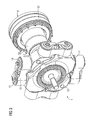
- die Kupplungsvorrichtung gemäß Figur in perspektivischer Darstellung.
- Die in
Figur 1 dargestellte Kupplungsvorrichtung zur Verbindung eines antreibenden Maschinenteils mit einem angetriebenen Maschinenteil umfaßt eine an einem ersten antriebs- oder abtriebsseitigen Endabschnitt der Kupplungsvorrichtung angeordnete gummielastische Kupplung 1, die im vorliegenden Ausführungsbeispiel als Gelenkhebelkupplung ausgestaltet ist. Grundsätzlich könnte die gummielastische Kupplung 1 auch als Laschenkupplung, Keilpaketkupplung, Stahllamellenkupplung mit gummielastischem Zwischenstück, Bolzenkupplung oder Klauenkupplung ausgestaltet sein. - Die Gelenkhebelkupplung 1 umfaßt einen ersten 11 und einen zweiten Anschlußflansch 12, die über 4 Lenkerelemente 13 miteinander verbunden sind. Der erste Anschlußflansch 11 der Gelenkhebelkupplung 1 ist im wesentlichen konzentrisch innerhalb des zweiten Anschlußflanschs 12 angeordnet, dessen armartige Fortsätze, an welche die Lagerzapfen angeformt sind, den ersten Anschlußflansch 11 im vorliegenden Ausführungsbeispiel radial zumindest partiell umgreifen.
- An einem zweiten abtriebs- oder antriebsseitigen Endabschnitt der Kupplungsvorrichtung ist eine Zahnkupplung 2 angeordnet, die ein inneres 22 und ein äußeres Kupplungselement 21 umfaßt. Das äußere Kupplungselement 21 bildet im vorliegenden Ausführungsbeispiel eine Verlängerung einer in den Figuren nicht näher dargestellten Getriebehohlwelle. Dabei kann die Zahnkupplung in die Getriebehohlwelle integriert oder vor diese montiert sein. Außerdem ist in das äußere Kupplungselement 21 ein Lagersitz für die Getriebehohlwelle integriert. Im vorliegenden Ausführungsbeispiel weist die Zahnkupplung 2 eine Bogenverzahnung auf und kann damit auch einen Winkelversatz zwischen einer Antriebswelle und einer Abtriebswelle ausgleichen. Des weiteren kann die Zahnkupplung 2 öl- oder fettgeschmiert sein.
- An einer getriebeseitigen Stirnseite der Zahnkupplung 2 ist ein Deckel 23 an das äußere Kupplungselement 21 geschraubt, so daß die Zahnkupplung 2 eine Abdichtung eines Getriebes bildet. Zwischen dem äußeren Kupplungselement 21 und einer Zwischenwelle 3, welche die Gelenkhebelkupplung 1 mit der Zahnkupplung 2 verbindet, ist ein stoßdämpfender Anlaufring 24 angeordnet, der einen Sitz für einen die Zwischenwelle 3 umgebenden Dichtring 25 und ein Begrenzungselement für axiale Relativbewegungen zwischen Zahnkupplung 2 und Zwischenwelle 3 bildet. Zusätzlich zum Dichtring 25 zwischen der Zwischenwelle 3 und dem Anlaufring 24 ist ein Dichtring 26 radial zwischen einem hohlwellenartigen Fortsatz des Deckels 23 und dem inneren Kupplungselement 22 angeordnet. Das innere Kupplungselement 22 ist im vorliegenden Ausführungsbeispiel einstückig an die Zwischenwelle 3 angeformt und bildet einen Sitz für den mit dem Deckel 23 verbundenen Dichtring 26.
- Die Zwischenwelle 3 ist im vorliegenden Ausführungsbeispiel zweistückig ausgestaltet. Ein erster Wellenabschnitt 31 der Zwischenwelle 3 ist mit dem zweiten Anschlußflansch 12 der Gelenkhebelkupplung 1 verbunden, während das innere Kupplungselement 22 der Zahnkupplung 2 an einen zweiten im wesentlichen hohlwellenartigen Wellenabschnitt 32 der Zwischenwelle 3 angeformt ist. Die beiden Wellenabschnitte 31, 32 der Zwischenwelle 3 werden zunächst mittels Verbindungsstiften 34, die in Bohrungen an den Wellenabschnitten 31, 32 gesteckt sind, aufeinander zentriert und anschließend mittels Schrauben 33 fest verbunden. Für Wartungs- oder Instandhaltungsarbeiten an der vorliegenden Kupplungsvorrichtung können die Schrauben 33 wieder gelöst werden.
- Die Zahnkupplung 2 und die Gelenkhebelkupplung 1 weisen derart aufeinander abgestimmte Rückstellkräfte auf, daß die Kupplungsvorrichtung bei einer radialen Verlagerung sowohl einen zentrischen Lauf als auch einen Axialversatzausgleich aufweist. Aufgrund elektrisch isolierender Werkstoffe an oder in mit den Anschlußflanschen 11, 12 der Gelenkhebelkupplung 1 verbundenen Lenkerelementen 13 kann ein Stromfluß durch ein mit der Kupplungsvorrichtung verbundenes Getriebe vermieden werden.
- Anhand der
Figuren 2 und3 ist zu erkennen, daß die Gelenkhebelkupplung 1 neben den Anschlußflanschen 11, 12 mit Lagerzapfen der Anschlußflansche 11, 12 verbundene Lenkerelemente 13 umfaßt. Zwischen den an die Anschlußflansche 11, 12 angeformten Lagerzapfen und den diese umgebenden Bohrungen der Lenkerelemente 13 sind gummielastische, elektrisch isolierende Buchsen 14 angeordnet, die mittels jeweils eines Sicherungsstücks 15 an die Lagerzapfen montiert sind. - Die Anwendung der vorliegenden Erfindung ist nicht auf das beschriebene Ausführungsbeispiel beschränkt.
Claims (9)
- Kupplungsvorrichtung zur Verbindung eines antreibenden Maschinenteils mit einem angetriebenen Maschinenteil mit- einer an einem ersten antriebs- oder abtriebsseitigen Endabschnitt der Kupplungsvorrichtung angeordneten gummielastischen Kupplung,- einer an einem zweiten abtriebs- oder antriebsseitigen Endabschnitt der Kupplungsvorrichtung angeordneten Zahnkupplung,- einer die gummielastische Kupplung mit der Zahnkupplung verbindenden Zwischenwelle, wobei die Zahnkupplung und die gummielastische Kupplung derart aufeinander abgestimmte Rückstellkräfte aufweisen, daß die Kupplungsvorrichtung bei einer radialen Verlagerung sowohl einen zentrischen Lauf als auch einen Axialversatzausgleich aufweist.
- Kupplungsvorrichtung nach Anspruch 1, bei dem die gummielastische Kupplung eine Gelenkhebelkupplung, eine Laschenkupplung, eine Keilpaketkupplung, eine Stahllamellenkupplung mit gummielastischem Zwischenstück, eine Bolzenkupplung oder eine Klauenkupplung umfaßt.
- Kupplungsvorrichtung nach einem der Ansprüche 1 oder 2, bei dem die Zahnkupplung eine Bogenverzahnung aufweist.
- Kupplungsvorrichtung nach einem der Ansprüche 1 bis 3, bei dem die Zahnkupplung in eine Getriebehohlwelle integriert ist.
- Kupplungsvorrichtung nach einem der Ansprüche 1 bis 3, bei dem die Zahnkupplung vor einer Getriebehohlwelle montiert ist.
- Kupplungsvorrichtung nach einem der Ansprüche 4 oder 5, bei dem die Zahnkupplung ein inneres und ein äußeres Kupplungselement umfaßt, bei dem das äußere Kupplungselement eine Verlängerung der Getriebehohlwelle bildet.
- Kupplungsvorrichtung nach Anspruch 6, bei dem in das äußere Kupplungselement ein Lagersitz für die Getriebehohlwelle integriert ist.
- Kupplungsvorrichtung nach einem der Ansprüche 4 bis 7, bei dem die Zahnkupplung eine Abdichtung eines Getriebes bildet.
- Kupplungsvorrichtung nach einem der Ansprüche 1 bis 8, bei dem die Zahnkupplung ein inneres und ein äußeres Kupplungselement umfaßt, bei dem zwischen dem äußeren Kupplungselement und der Zwischenwelle ein stoßdämpfender Anlaufring angeordnet ist, der einen Sitz für einen die Zwischenwelle umgebenden Dichtring und ein Begrenzungselement für axiale Relativbewegungen zwischen Zahnkupplung und Zwischenwelle bildet.
Priority Applications (5)
| Application Number | Priority Date | Filing Date | Title |
|---|---|---|---|
| EP20100015090 EP2457795B1 (de) | 2010-11-29 | 2010-11-29 | Kupplungsvorrichtung |
| ES10015090T ES2427846T3 (es) | 2010-11-29 | 2010-11-29 | Dispositivo de acoplamiento |
| CA2759533A CA2759533C (en) | 2010-11-29 | 2011-11-25 | Clutch device |
| CN201110386820.5A CN102537097B (zh) | 2010-11-29 | 2011-11-29 | 联轴器装置 |
| US13/306,362 US8900061B2 (en) | 2010-11-29 | 2011-11-29 | Clutch device |
Applications Claiming Priority (1)
| Application Number | Priority Date | Filing Date | Title |
|---|---|---|---|
| EP20100015090 EP2457795B1 (de) | 2010-11-29 | 2010-11-29 | Kupplungsvorrichtung |
Publications (2)
| Publication Number | Publication Date |
|---|---|
| EP2457795A1 true EP2457795A1 (de) | 2012-05-30 |
| EP2457795B1 EP2457795B1 (de) | 2013-08-28 |
Family
ID=43736165
Family Applications (1)
| Application Number | Title | Priority Date | Filing Date |
|---|---|---|---|
| EP20100015090 Active EP2457795B1 (de) | 2010-11-29 | 2010-11-29 | Kupplungsvorrichtung |
Country Status (5)
| Country | Link |
|---|---|
| US (1) | US8900061B2 (de) |
| EP (1) | EP2457795B1 (de) |
| CN (1) | CN102537097B (de) |
| CA (1) | CA2759533C (de) |
| ES (1) | ES2427846T3 (de) |
Cited By (2)
| Publication number | Priority date | Publication date | Assignee | Title |
|---|---|---|---|---|
| DE102019131157A1 (de) * | 2019-11-19 | 2021-05-20 | Voith Patent Gmbh | Antriebseinheit für ein Schienenfahrzeug, sowie Hohlwelle für eine solche |
| EP3926196A1 (de) | 2020-06-19 | 2021-12-22 | Flender GmbH | Doppelgelenkkupplung, drehgestell, schienenfahrzeug, industrie-applikation und computerprogrammprodukt |
Families Citing this family (5)
| Publication number | Priority date | Publication date | Assignee | Title |
|---|---|---|---|---|
| DE102013210076A1 (de) | 2013-05-29 | 2014-12-04 | Siemens Aktiengesellschaft | Kupplungsnabe |
| CN104819218B (zh) * | 2015-05-05 | 2018-08-14 | 湖州灵动智能设备有限公司 | 一种可承受大的径向冲击和载荷的联轴器 |
| US10124666B2 (en) | 2015-09-08 | 2018-11-13 | High Stone Technologies, LLC | Wheelchair drive boost |
| CN117646765B (zh) * | 2024-01-30 | 2024-05-03 | 吉林天池钼业有限公司 | 一种输出部带自启动功能的联轴器 |
| CN119705051B (zh) * | 2025-02-13 | 2025-07-22 | 江苏爱尔特实业有限公司 | 一种汽车传动轴支撑结构 |
Citations (5)
| Publication number | Priority date | Publication date | Assignee | Title |
|---|---|---|---|---|
| FR1196352A (fr) * | 1958-05-23 | 1959-11-24 | Tacke Maschinenfabrik Komm Ges | Accouplement denté angulairement mobile |
| DE10050757A1 (de) | 2000-10-13 | 2002-04-25 | Zahnradfabrik Friedrichshafen | Antriebseinheit für Schienenfahrzeuge |
| DE10257018A1 (de) | 2002-07-16 | 2004-02-05 | A. Friedr. Flender Gmbh | Kupplung |
| DE202005015769U1 (de) * | 2005-09-30 | 2006-01-19 | Kwd Kupplungswerk Dresden Gmbh | Kardanische Doppelgelenkkupplung für Schienenfahrzeuge |
| JP2007314133A (ja) * | 2006-05-29 | 2007-12-06 | Jtekt Corp | 輪軸及び台車 |
Family Cites Families (2)
| Publication number | Priority date | Publication date | Assignee | Title |
|---|---|---|---|---|
| US1659353A (en) * | 1927-08-16 | 1928-02-14 | William S Dwyer | Flexible coupling for rotary members |
| US3013411A (en) * | 1960-04-12 | 1961-12-19 | Gunnar A Wahlmark | Gear type constant velocity joint |
-
2010
- 2010-11-29 ES ES10015090T patent/ES2427846T3/es active Active
- 2010-11-29 EP EP20100015090 patent/EP2457795B1/de active Active
-
2011
- 2011-11-25 CA CA2759533A patent/CA2759533C/en active Active
- 2011-11-29 US US13/306,362 patent/US8900061B2/en active Active
- 2011-11-29 CN CN201110386820.5A patent/CN102537097B/zh active Active
Patent Citations (5)
| Publication number | Priority date | Publication date | Assignee | Title |
|---|---|---|---|---|
| FR1196352A (fr) * | 1958-05-23 | 1959-11-24 | Tacke Maschinenfabrik Komm Ges | Accouplement denté angulairement mobile |
| DE10050757A1 (de) | 2000-10-13 | 2002-04-25 | Zahnradfabrik Friedrichshafen | Antriebseinheit für Schienenfahrzeuge |
| DE10257018A1 (de) | 2002-07-16 | 2004-02-05 | A. Friedr. Flender Gmbh | Kupplung |
| DE202005015769U1 (de) * | 2005-09-30 | 2006-01-19 | Kwd Kupplungswerk Dresden Gmbh | Kardanische Doppelgelenkkupplung für Schienenfahrzeuge |
| JP2007314133A (ja) * | 2006-05-29 | 2007-12-06 | Jtekt Corp | 輪軸及び台車 |
Cited By (4)
| Publication number | Priority date | Publication date | Assignee | Title |
|---|---|---|---|---|
| DE102019131157A1 (de) * | 2019-11-19 | 2021-05-20 | Voith Patent Gmbh | Antriebseinheit für ein Schienenfahrzeug, sowie Hohlwelle für eine solche |
| EP3926196A1 (de) | 2020-06-19 | 2021-12-22 | Flender GmbH | Doppelgelenkkupplung, drehgestell, schienenfahrzeug, industrie-applikation und computerprogrammprodukt |
| WO2021254670A1 (de) | 2020-06-19 | 2021-12-23 | Flender Gmbh | Doppelgelenkkupplung, drehgestell, schienenfahrzeug, industrie-applikation und computerprogrammprodukt |
| US12480548B2 (en) | 2020-06-19 | 2025-11-25 | Flender Gmbh | Double-jointed coupling, bogie, rail vehicle, industrial application and computer program product |
Also Published As
| Publication number | Publication date |
|---|---|
| ES2427846T3 (es) | 2013-11-04 |
| EP2457795B1 (de) | 2013-08-28 |
| CN102537097A (zh) | 2012-07-04 |
| US20120132497A1 (en) | 2012-05-31 |
| US8900061B2 (en) | 2014-12-02 |
| CA2759533A1 (en) | 2012-05-29 |
| CN102537097B (zh) | 2014-09-17 |
| CA2759533C (en) | 2014-09-30 |
Similar Documents
| Publication | Publication Date | Title |
|---|---|---|
| EP2457795B1 (de) | Kupplungsvorrichtung | |
| EP2758684B1 (de) | Kupplung mit kupplungsring auf zwei kupplungsteilen und zugehöriger kupplungsring | |
| EP3234388B1 (de) | Kupplungsvorrichtung und fadenverstärkte gelenkvorrichtung | |
| EP1940667B1 (de) | Kardanische doppelgelenkkupplung für schienenfahrzeuge | |
| WO2016046019A1 (de) | Kupplungsvorrichtung | |
| EP2611666A1 (de) | Getriebe für einen schienenfahrzeugantriebsstrang | |
| DE102013222753A1 (de) | Doppel-Torsionskupplung für ein Schienenfahrzeug und Verfahren zur Montage einer Doppel-Torsionskupplung | |
| WO2010060626A1 (de) | Drehmomentübertragungsvorrichtung | |
| EP0632210B1 (de) | Zahnkupplung, insbesondere für ein Antriebsaggregat eines Schienenfahrzeugs | |
| DE102014204224A1 (de) | Ausgleichskupplung mit Verbindungsteilen | |
| EP1377489B1 (de) | Fahrzeugantrieb mit bogenzahnkupplung | |
| DE102014204221B4 (de) | Ausgleichskupplung mit Distanzelement sowie Kupplungsanordnung | |
| EP0584821A2 (de) | Elastische Wellenkupplung | |
| DE102016015264A1 (de) | Gleichlaufgelenk für eine Gelenkwelle eines Antriebsstrangs eines Kraftfahrzeugs, sowie Verbindungsanordnung eines solchen Gleichlaufgelenks an einem Getriebeflansch | |
| EP1360425B1 (de) | Flanschmitnehmer | |
| EP1382870B1 (de) | Elastische Kupplung | |
| EP3686076A1 (de) | Getriebegehäuse und anordnung zur abstützung eines getriebes | |
| DE102015005317A1 (de) | Kupplungsvorrichtung und Verfahren zum Montieren einer solchen Kupplungsvorrichtung | |
| EP4034445B1 (de) | Kupplung für schienenfahrzeuge | |
| DE102014200424B4 (de) | Fahrwerk für ein Schienenfahrzeug | |
| DE102012003037B4 (de) | Elastische Torsionskupplung | |
| DE102015102843B4 (de) | Elastische Kupplungsvorrichtung zur Drehmomentübertragung zwischen zwei Wellenenden | |
| DE102011003324A1 (de) | Flanschverbindung zwischen einem Getriebegehäuse und einem Motorschwungradgehäuse eines Kraftfahrzeugs | |
| EP1691096B1 (de) | Axiale Isolierung für ein kardanisches Kreuzgelenk | |
| EP1691099B1 (de) | Axiale Isolierung für ein kardanisches Kreuzgelenk |
Legal Events
| Date | Code | Title | Description |
|---|---|---|---|
| PUAI | Public reference made under article 153(3) epc to a published international application that has entered the european phase |
Free format text: ORIGINAL CODE: 0009012 |
|
| 17P | Request for examination filed |
Effective date: 20110418 |
|
| AK | Designated contracting states |
Kind code of ref document: A1 Designated state(s): AL AT BE BG CH CY CZ DE DK EE ES FI FR GB GR HR HU IE IS IT LI LT LU LV MC MK MT NL NO PL PT RO RS SE SI SK SM TR |
|
| AX | Request for extension of the european patent |
Extension state: BA ME |
|
| RAP1 | Party data changed (applicant data changed or rights of an application transferred) |
Owner name: SIEMENS AKTIENGESELLSCHAFT |
|
| RIC1 | Information provided on ipc code assigned before grant |
Ipc: B61C 9/44 20060101AFI20130201BHEP Ipc: F16D 3/18 20060101ALI20130201BHEP Ipc: F16D 3/62 20060101ALI20130201BHEP |
|
| GRAP | Despatch of communication of intention to grant a patent |
Free format text: ORIGINAL CODE: EPIDOSNIGR1 |
|
| GRAS | Grant fee paid |
Free format text: ORIGINAL CODE: EPIDOSNIGR3 |
|
| GRAA | (expected) grant |
Free format text: ORIGINAL CODE: 0009210 |
|
| AK | Designated contracting states |
Kind code of ref document: B1 Designated state(s): AL AT BE BG CH CY CZ DE DK EE ES FI FR GB GR HR HU IE IS IT LI LT LU LV MC MK MT NL NO PL PT RO RS SE SI SK SM TR |
|
| REG | Reference to a national code |
Ref country code: GB Ref legal event code: FG4D Free format text: NOT ENGLISH |
|
| REG | Reference to a national code |
Ref country code: CH Ref legal event code: EP |
|
| REG | Reference to a national code |
Ref country code: AT Ref legal event code: REF Ref document number: 629151 Country of ref document: AT Kind code of ref document: T Effective date: 20130915 |
|
| REG | Reference to a national code |
Ref country code: IE Ref legal event code: FG4D Free format text: LANGUAGE OF EP DOCUMENT: GERMAN |
|
| REG | Reference to a national code |
Ref country code: DE Ref legal event code: R096 Ref document number: 502010004480 Country of ref document: DE Effective date: 20131024 |
|
| REG | Reference to a national code |
Ref country code: ES Ref legal event code: FG2A Ref document number: 2427846 Country of ref document: ES Kind code of ref document: T3 Effective date: 20131104 |
|
| REG | Reference to a national code |
Ref country code: LT Ref legal event code: MG4D |
|
| REG | Reference to a national code |
Ref country code: NL Ref legal event code: VDEP Effective date: 20130828 |
|
| PG25 | Lapsed in a contracting state [announced via postgrant information from national office to epo] |
Ref country code: LT Free format text: LAPSE BECAUSE OF FAILURE TO SUBMIT A TRANSLATION OF THE DESCRIPTION OR TO PAY THE FEE WITHIN THE PRESCRIBED TIME-LIMIT Effective date: 20130828 Ref country code: SE Free format text: LAPSE BECAUSE OF FAILURE TO SUBMIT A TRANSLATION OF THE DESCRIPTION OR TO PAY THE FEE WITHIN THE PRESCRIBED TIME-LIMIT Effective date: 20130828 Ref country code: CY Free format text: LAPSE BECAUSE OF FAILURE TO SUBMIT A TRANSLATION OF THE DESCRIPTION OR TO PAY THE FEE WITHIN THE PRESCRIBED TIME-LIMIT Effective date: 20130828 Ref country code: IS Free format text: LAPSE BECAUSE OF FAILURE TO SUBMIT A TRANSLATION OF THE DESCRIPTION OR TO PAY THE FEE WITHIN THE PRESCRIBED TIME-LIMIT Effective date: 20131228 Ref country code: PT Free format text: LAPSE BECAUSE OF FAILURE TO SUBMIT A TRANSLATION OF THE DESCRIPTION OR TO PAY THE FEE WITHIN THE PRESCRIBED TIME-LIMIT Effective date: 20131230 Ref country code: NO Free format text: LAPSE BECAUSE OF FAILURE TO SUBMIT A TRANSLATION OF THE DESCRIPTION OR TO PAY THE FEE WITHIN THE PRESCRIBED TIME-LIMIT Effective date: 20131128 Ref country code: HR Free format text: LAPSE BECAUSE OF FAILURE TO SUBMIT A TRANSLATION OF THE DESCRIPTION OR TO PAY THE FEE WITHIN THE PRESCRIBED TIME-LIMIT Effective date: 20130828 |
|
| REG | Reference to a national code |
Ref country code: NL Ref legal event code: VDEP Effective date: 20130828 |
|
| PG25 | Lapsed in a contracting state [announced via postgrant information from national office to epo] |
Ref country code: GR Free format text: LAPSE BECAUSE OF FAILURE TO SUBMIT A TRANSLATION OF THE DESCRIPTION OR TO PAY THE FEE WITHIN THE PRESCRIBED TIME-LIMIT Effective date: 20131129 Ref country code: FI Free format text: LAPSE BECAUSE OF FAILURE TO SUBMIT A TRANSLATION OF THE DESCRIPTION OR TO PAY THE FEE WITHIN THE PRESCRIBED TIME-LIMIT Effective date: 20130828 Ref country code: SI Free format text: LAPSE BECAUSE OF FAILURE TO SUBMIT A TRANSLATION OF THE DESCRIPTION OR TO PAY THE FEE WITHIN THE PRESCRIBED TIME-LIMIT Effective date: 20130828 Ref country code: LV Free format text: LAPSE BECAUSE OF FAILURE TO SUBMIT A TRANSLATION OF THE DESCRIPTION OR TO PAY THE FEE WITHIN THE PRESCRIBED TIME-LIMIT Effective date: 20130828 Ref country code: PL Free format text: LAPSE BECAUSE OF FAILURE TO SUBMIT A TRANSLATION OF THE DESCRIPTION OR TO PAY THE FEE WITHIN THE PRESCRIBED TIME-LIMIT Effective date: 20130828 |
|
| PG25 | Lapsed in a contracting state [announced via postgrant information from national office to epo] |
Ref country code: CZ Free format text: LAPSE BECAUSE OF FAILURE TO SUBMIT A TRANSLATION OF THE DESCRIPTION OR TO PAY THE FEE WITHIN THE PRESCRIBED TIME-LIMIT Effective date: 20130828 Ref country code: EE Free format text: LAPSE BECAUSE OF FAILURE TO SUBMIT A TRANSLATION OF THE DESCRIPTION OR TO PAY THE FEE WITHIN THE PRESCRIBED TIME-LIMIT Effective date: 20130828 Ref country code: DK Free format text: LAPSE BECAUSE OF FAILURE TO SUBMIT A TRANSLATION OF THE DESCRIPTION OR TO PAY THE FEE WITHIN THE PRESCRIBED TIME-LIMIT Effective date: 20130828 Ref country code: NL Free format text: LAPSE BECAUSE OF FAILURE TO SUBMIT A TRANSLATION OF THE DESCRIPTION OR TO PAY THE FEE WITHIN THE PRESCRIBED TIME-LIMIT Effective date: 20130828 Ref country code: RO Free format text: LAPSE BECAUSE OF FAILURE TO SUBMIT A TRANSLATION OF THE DESCRIPTION OR TO PAY THE FEE WITHIN THE PRESCRIBED TIME-LIMIT Effective date: 20130828 Ref country code: SK Free format text: LAPSE BECAUSE OF FAILURE TO SUBMIT A TRANSLATION OF THE DESCRIPTION OR TO PAY THE FEE WITHIN THE PRESCRIBED TIME-LIMIT Effective date: 20130828 |
|
| REG | Reference to a national code |
Ref country code: DE Ref legal event code: R097 Ref document number: 502010004480 Country of ref document: DE |
|
| PLBE | No opposition filed within time limit |
Free format text: ORIGINAL CODE: 0009261 |
|
| STAA | Information on the status of an ep patent application or granted ep patent |
Free format text: STATUS: NO OPPOSITION FILED WITHIN TIME LIMIT |
|
| PG25 | Lapsed in a contracting state [announced via postgrant information from national office to epo] |
Ref country code: MC Free format text: LAPSE BECAUSE OF FAILURE TO SUBMIT A TRANSLATION OF THE DESCRIPTION OR TO PAY THE FEE WITHIN THE PRESCRIBED TIME-LIMIT Effective date: 20130828 |
|
| 26N | No opposition filed |
Effective date: 20140530 |
|
| REG | Reference to a national code |
Ref country code: IE Ref legal event code: MM4A |
|
| REG | Reference to a national code |
Ref country code: DE Ref legal event code: R097 Ref document number: 502010004480 Country of ref document: DE Effective date: 20140530 |
|
| PG25 | Lapsed in a contracting state [announced via postgrant information from national office to epo] |
Ref country code: IE Free format text: LAPSE BECAUSE OF NON-PAYMENT OF DUE FEES Effective date: 20131129 |
|
| PG25 | Lapsed in a contracting state [announced via postgrant information from national office to epo] |
Ref country code: SM Free format text: LAPSE BECAUSE OF FAILURE TO SUBMIT A TRANSLATION OF THE DESCRIPTION OR TO PAY THE FEE WITHIN THE PRESCRIBED TIME-LIMIT Effective date: 20130828 |
|
| PG25 | Lapsed in a contracting state [announced via postgrant information from national office to epo] |
Ref country code: TR Free format text: LAPSE BECAUSE OF FAILURE TO SUBMIT A TRANSLATION OF THE DESCRIPTION OR TO PAY THE FEE WITHIN THE PRESCRIBED TIME-LIMIT Effective date: 20130828 |
|
| REG | Reference to a national code |
Ref country code: CH Ref legal event code: PL |
|
| PG25 | Lapsed in a contracting state [announced via postgrant information from national office to epo] |
Ref country code: CH Free format text: LAPSE BECAUSE OF NON-PAYMENT OF DUE FEES Effective date: 20141130 Ref country code: HU Free format text: LAPSE BECAUSE OF FAILURE TO SUBMIT A TRANSLATION OF THE DESCRIPTION OR TO PAY THE FEE WITHIN THE PRESCRIBED TIME-LIMIT; INVALID AB INITIO Effective date: 20101129 Ref country code: BG Free format text: LAPSE BECAUSE OF FAILURE TO SUBMIT A TRANSLATION OF THE DESCRIPTION OR TO PAY THE FEE WITHIN THE PRESCRIBED TIME-LIMIT Effective date: 20130828 Ref country code: MK Free format text: LAPSE BECAUSE OF FAILURE TO SUBMIT A TRANSLATION OF THE DESCRIPTION OR TO PAY THE FEE WITHIN THE PRESCRIBED TIME-LIMIT Effective date: 20130828 Ref country code: LU Free format text: LAPSE BECAUSE OF NON-PAYMENT OF DUE FEES Effective date: 20131129 Ref country code: RS Free format text: LAPSE BECAUSE OF FAILURE TO SUBMIT A TRANSLATION OF THE DESCRIPTION OR TO PAY THE FEE WITHIN THE PRESCRIBED TIME-LIMIT Effective date: 20131128 Ref country code: LI Free format text: LAPSE BECAUSE OF NON-PAYMENT OF DUE FEES Effective date: 20141130 |
|
| PG25 | Lapsed in a contracting state [announced via postgrant information from national office to epo] |
Ref country code: MT Free format text: LAPSE BECAUSE OF FAILURE TO SUBMIT A TRANSLATION OF THE DESCRIPTION OR TO PAY THE FEE WITHIN THE PRESCRIBED TIME-LIMIT Effective date: 20130828 |
|
| REG | Reference to a national code |
Ref country code: FR Ref legal event code: PLFP Year of fee payment: 6 |
|
| REG | Reference to a national code |
Ref country code: FR Ref legal event code: PLFP Year of fee payment: 7 |
|
| REG | Reference to a national code |
Ref country code: AT Ref legal event code: MM01 Ref document number: 629151 Country of ref document: AT Kind code of ref document: T Effective date: 20151129 |
|
| PG25 | Lapsed in a contracting state [announced via postgrant information from national office to epo] |
Ref country code: AT Free format text: LAPSE BECAUSE OF NON-PAYMENT OF DUE FEES Effective date: 20151129 |
|
| REG | Reference to a national code |
Ref country code: FR Ref legal event code: PLFP Year of fee payment: 8 |
|
| REG | Reference to a national code |
Ref country code: DE Ref legal event code: R081 Ref document number: 502010004480 Country of ref document: DE Owner name: FLENDER GMBH, DE Free format text: FORMER OWNER: SIEMENS AKTIENGESELLSCHAFT, 80333 MUENCHEN, DE |
|
| REG | Reference to a national code |
Ref country code: ES Ref legal event code: PC2A Owner name: FLENDER GMBH Effective date: 20171219 |
|
| REG | Reference to a national code |
Ref country code: GB Ref legal event code: 732E Free format text: REGISTERED BETWEEN 20171207 AND 20171213 |
|
| REG | Reference to a national code |
Ref country code: BE Ref legal event code: PD Owner name: FLENDER GMBH; DE Free format text: DETAILS ASSIGNMENT: CHANGE OF OWNER(S), AFFECTATION / CESSION; FORMER OWNER NAME: SIEMENS AKTIENGESELLSCHAFT Effective date: 20171117 |
|
| REG | Reference to a national code |
Ref country code: FR Ref legal event code: TP Owner name: FLENDER GMBH, DE Effective date: 20180316 |
|
| PG25 | Lapsed in a contracting state [announced via postgrant information from national office to epo] |
Ref country code: AL Free format text: LAPSE BECAUSE OF FAILURE TO SUBMIT A TRANSLATION OF THE DESCRIPTION OR TO PAY THE FEE WITHIN THE PRESCRIBED TIME-LIMIT Effective date: 20130828 |
|
| REG | Reference to a national code |
Ref country code: DE Ref legal event code: R082 Ref document number: 502010004480 Country of ref document: DE Representative=s name: MICHALSKI HUETTERMANN & PARTNER PATENTANWAELTE, DE |
|
| REG | Reference to a national code |
Ref country code: DE Ref legal event code: R039 Ref document number: 502010004480 Country of ref document: DE Ref country code: DE Ref legal event code: R008 Ref document number: 502010004480 Country of ref document: DE |
|
| REG | Reference to a national code |
Ref country code: DE Ref legal event code: R040 Ref document number: 502010004480 Country of ref document: DE |
|
| REG | Reference to a national code |
Ref country code: GB Ref legal event code: 732E Free format text: REGISTERED BETWEEN 20240509 AND 20240515 |
|
| PGFP | Annual fee paid to national office [announced via postgrant information from national office to epo] |
Ref country code: DE Payment date: 20251126 Year of fee payment: 16 |
|
| PGFP | Annual fee paid to national office [announced via postgrant information from national office to epo] |
Ref country code: GB Payment date: 20251121 Year of fee payment: 16 |
|
| PGFP | Annual fee paid to national office [announced via postgrant information from national office to epo] |
Ref country code: IT Payment date: 20251125 Year of fee payment: 16 |
|
| PGFP | Annual fee paid to national office [announced via postgrant information from national office to epo] |
Ref country code: FR Payment date: 20251125 Year of fee payment: 16 |
|
| PGFP | Annual fee paid to national office [announced via postgrant information from national office to epo] |
Ref country code: BE Payment date: 20251119 Year of fee payment: 16 |
|
| PGFP | Annual fee paid to national office [announced via postgrant information from national office to epo] |
Ref country code: ES Payment date: 20251229 Year of fee payment: 16 |