EP4034445B1 - Kupplung für schienenfahrzeuge - Google Patents
Kupplung für schienenfahrzeuge Download PDFInfo
- Publication number
- EP4034445B1 EP4034445B1 EP20780652.2A EP20780652A EP4034445B1 EP 4034445 B1 EP4034445 B1 EP 4034445B1 EP 20780652 A EP20780652 A EP 20780652A EP 4034445 B1 EP4034445 B1 EP 4034445B1
- Authority
- EP
- European Patent Office
- Prior art keywords
- coupling
- shaft
- stud bolt
- coupling half
- transmission shaft
- Prior art date
- Legal status (The legal status is an assumption and is not a legal conclusion. Google has not performed a legal analysis and makes no representation as to the accuracy of the status listed.)
- Active
Links
Images



Classifications
-
- B—PERFORMING OPERATIONS; TRANSPORTING
- B61—RAILWAYS
- B61C—LOCOMOTIVES; MOTOR RAILCARS
- B61C9/00—Locomotives or motor railcars characterised by the type of transmission system used; Transmission systems specially adapted for locomotives or motor railcars
- B61C9/38—Transmission systems in or for locomotives or motor railcars with electric motor propulsion
- B61C9/44—Transmission systems in or for locomotives or motor railcars with electric motor propulsion with hollow transmission shaft concentric with wheel axis
Definitions
- the invention relates to the field of rail vehicle technology and concerns a coupling for rail vehicles.
- the coupling according to the invention can be used in particular in rail vehicles that have a double-cardanic coupling to compensate for axial, radial and angular displacements between the transmission and the wheel.
- Known couplings for rail vehicles are used as transmission means to transfer the torques emanating from a motor shaft to the wheel of the rail vehicle via a gearbox and a subsequently arranged coupling connected to the gearbox and the wheel.
- a cardanic double-joint coupling for rail vehicles with two joint planes which contains two coupling joints and is connected to one another for torque transmission by a hollow pinion shaft via a shaft enclosed by the hollow pinion shaft.
- One joint plane is assigned to a coupling joint with crowned teeth with angular and axial compensation capacity and the other joint plane is assigned to a torsionally rigid, flexurally elastic coupling joint.
- the coupling joint with crowned teeth has an exchangeable sleeve with internal teeth and an exchangeable coupling hub with associated external teeth, whereby the shaft designed as an intermediate shaft is connected to the exchangeable coupling hub at the end area and the hollow pinion shaft is attached outside the exchangeable sleeve to the outer wall of the sleeve.
- a drive unit for rail vehicles with an electric motor suspended on the vehicle frame or chassis a gearbox and a cardan-acting coupling system is known, with the coupling system being arranged between a wheel set shaft and the gearbox.
- a first part of the coupling system is integrated in the form of a curved tooth coupling into the output gear of the gearbox and into its lubricating oil circuit.
- a second part of the coupling system on the output side is provided between the gearbox and the wheel set.
- a transmission unit for driving a wheel in particular a wheel of a rail vehicle, with a transmission, a connecting shaft for connecting the wheel and the transmission, and a two-part coupling system provided between the wheel and the transmission, arranged on the connecting shaft and acting as a cardan, wherein the connecting shaft is guided through the hollow wheel hub and a first part of a coupling system is arranged on the side of the wheel facing the transmission and a second part is arranged on the side of the wheel facing away from the transmission, wherein the two parts of the connecting shaft are connected at the separation point by means of a central screw.
- a low-floor vehicle transmission and wheel-to-wheel connection structure is known in which the transmission output shaft is a hollow shaft with a center hole and an axle or an end of the wheel is provided with a threaded hole, and the hollow shaft is fixedly connected to the axle or wheel by a preloaded large bolt passing through the center hole.
- the object of the present invention is to provide a coupling for rail vehicles which is at least 2-part, which is easy and safe to assemble, largely avoids damage during assembly of the coupling and has a high positional accuracy of the joined coupling halves.
- the solution according to the invention relates to a coupling for rail vehicles, containing a two-part coupling system which has a first coupling half facing a drive and a second coupling half facing a wheel, wherein the first coupling half is connected to the drive and has at least a first coupling shaft and a drive-side sleeve, and wherein the second coupling half is connected to a wheel of the rail vehicle and has a second coupling shaft, wherein the second coupling shaft is guided through a hollow hub of a wheel, and wherein the separation point of the first and second coupling shafts is realized in such a way that on the respective mutually facing end faces of the coupling shafts there are toothings or friction surfaces which transmit at least one torque at least in a force-locking and/or form-locking manner, wherein a pre-assembled stud bolt arranged centrally axially in the second coupling shaft is used at least for aligning, centering, guiding and checking the second coupling half to the first Coupling half is present,
- the solution according to the invention also relates to a coupling for rail vehicles, containing a 3-part coupling system which has a first coupling half facing a drive and a second coupling half facing a wheel and a transmission shaft, wherein the first coupling half is connected to the drive and has at least a first coupling shaft and a drive-side sleeve, and wherein the second coupling half is connected to a wheel of the rail vehicle and has a second coupling shaft, wherein the second coupling shaft is guided through a hollow hub of a wheel, and wherein the separation point of the first and second coupling shaft with the transmission shaft is realized in such a way that on the respective mutually facing end faces of the coupling shafts and the transmission shaft there are toothings and/or friction surfaces with which a torque can be transmitted at least in a force-locking and/or form-locking manner, wherein a transmission shaft is arranged axially aligned between the coupling shafts of the first and second coupling halves, which is detachably connected
- the first coupling half is a toothed coupling and/or the second coupling half which can be released from the transmission shaft is a toothed coupling, a ring disc coupling, a wedge pack ring coupling, a wedge pack, a link coupling or a handlebar coupling.
- connection of the transmission shaft with the first and/or the second coupling half is realized by means of spur gearing, face gearing, interference fit and/or flange screwing.
- a pre-assembled stud bolt is arranged centrally axially in the second coupling shaft, which extends through a through hole of the transmission shaft and a through hole of the first coupling half and protrudes from the first coupling half.
- At least one stud bolt is screwed in, glued in and/or pre-assembled by means of a press fit.
- the fit between the through hole and the stud bolt is designed as a sliding fit or a sliding fit.
- connection between the transmission shaft and the second clutch shaft of the second clutch half facing the wheel is realized by means of a stud bolt, a wheel-side screw or a press fit.
- the drive-side sleeve has an opening with a closure element, wherein the closure element is particularly advantageously a closure plug or a closure screw.
- the first clutch half is connected to a gearbox or directly to an engine.
- connection of the second coupling half to the wheel and/or the earthing contact element is realized in a form-fitting, force-fitting or material-fitting manner.
- the present invention provides a coupling for rail vehicles which is designed as a 2-part or 3-part coupling system and is characterized in particular by simple, cost-effective and safe assembly.
- the coupling according to the invention enables quick and cost-effective maintenance and repair and, in the case of a 3-part coupling system, quick adaptation to different track widths of different rail systems due to the simplified production of the individual parts.
- a coupling for rail vehicles in which a centrally axially arranged stud bolt is pre-assembled in the coupling shaft of the second coupling half in a 2-part coupling system.
- the centrally axially pre-assembled stud bolt is inserted at one end into the coupling shaft of the second coupling half and can be screwed in there with a force fit, locked with a form fit and/or glued in with a material fit.
- the other end of the stud bolt is completely passed through a through hole that is centrally axially inserted in the coupling shaft of the first coupling half and protrudes from the first coupling half.
- At least the protruding area of the stud bolt is provided with an external thread onto which a nut is screwed, which is used to connect the two coupling halves in a 2-part coupling system.
- At least one stud bolt according to the invention is also used in the 3-part clutch system according to the invention.
- a transmission shaft is arranged axially aligned between the first clutch half assigned to the drive and the second clutch half assigned to the wheel, into which at least one stud bolt is pre-mounted at one or both ends and axially centrically.
- the stud bolt according to the invention represents a simple and effective assembly aid for aligning the two coupling halves when bringing the first and second coupling halves together. Damage caused by collisions with the corresponding gears that are present on the front sides of the first and second coupling shafts or on the front side of the transmission shaft at the point where the two coupling halves are separated is thus effectively and easily avoided.
- the stud bolt according to the invention is a centering and guiding aid for finding the central position and for bringing the two coupling halves together in a controlled manner. This ensures that when assembling the two coupling halves, the stud bolt can be easily inserted into the opening of the prefabricated through hole of the first coupling half and by subsequently guiding the stud bolt through the through hole already present in the first coupling shaft in the first coupling half assigned to the drive, a defined translatory movement is achieved when bringing the two coupling halves together.
- the stud bolt has a section tapering towards the end of the stud bolt at the end which is inserted into the through hole of the first or second clutch shaft in order to facilitate the damage-free insertion of the stud bolt into the through hole during assembly of the clutch.
- a further technical advantage is that the stud bolt according to the invention can be used to check the correct and precisely positioned assembly of the two coupling halves. This makes it possible to check the correct fit of the first and second coupling halves using a specified test dimension, for example a test gauge, by measuring the protruding projection of the stud bolt or the seat of the nut on the stud bolt through the opening of the drive-side sleeve and, if necessary, correct the position of the coupling halves relative to each other.
- a specified test dimension for example a test gauge
- the two coupling halves are screwed together using a nut via the external thread located at the end of the stud bolt protruding from the first coupling half.
- the two coupling halves are separated in a simple manner by loosening and removing the nut from the stud bolt according to the invention using a tool that can be inserted through the opening in the sleeve.
- the fit of the stud bolt and the through hole is designed as a sliding fit or a sliding fit.
- a sliding fit or a sliding fit of the through hole and stud bolt enables the stud bolt to be inserted safely, precisely and quickly into the through hole of the first coupling half with little effort due to the low friction of the stud bolt in the through hole when the coupling halves are joined together.
- the advantageous fit ensures that a high level of axial positioning accuracy is achieved when assembling the first and second coupling halves, which avoids the need for complex axial readjustment of the two coupling halves.
- the clutch system can have a transmission shaft arranged axially aligned with the first and second clutch shafts between the first clutch half facing the drive and the second clutch half facing the wheel.
- the first and second clutch halves are each connected to the transmission shaft via a detachable connection.
- connection of the transmission shaft with the first coupling half associated with the drive is always realized via the stud bolt pre-mounted centrally in the transmission shaft, which is inserted into the Coupling is guided through the centrally axially inserted through hole in the first coupling half and is screwed at the end with a nut.
- connection of the transmission shaft with the second coupling half associated with the wheel can advantageously be designed in different ways. It is possible for the connection to also be made using a stud bolt that is already pre-assembled in the end area of the transmission shaft.
- the second coupling half is screwed on in the same way as on the drive side using a nut that is screwed onto the external thread of the stud bolt.
- connection between the transmission shaft and the second coupling half is realized by a screw fed on the wheel side or by a press fit.
- the detachable connections at both ends of the transmission shaft with the first and second clutch halves ensure that if one or both clutch halves wear out, they can be replaced independently of the transmission shaft. This saves maintenance and repair costs, as only the clutch halves that are actually worn out need to be replaced. This means that it is not necessary to remove and replace the transmission shaft from the hollow wheel hub of the wheel.
- a further advantage of detachable connections between the transmission shaft and the first and second coupling halves is that the 3-part coupling system can be easily and cost-effectively adapted to different track gauges of different regional rail systems by variably adjusting the length of the transmission shaft.
- the 3-part clutch system allows the first clutch half assigned to the drive and the second clutch half assigned to the wheel to be variably combined with each other in terms of their design and function, which means that the use of the clutch can be variably adapted to the desired applications.
- the first clutch half assigned to the drive it is possible for the first clutch half assigned to the drive to be used as a toothed clutch and the second clutch half assigned to the wheel
- the associated second coupling half is designed as a ring disk coupling, wedge pack ring coupling, wedge pack link coupling, link coupling or also as a toothed coupling. This enables a wide range of applications for the coupling according to the invention.
- a 3-part clutch Another advantage of a 3-part clutch is that the manufacturing costs can be reduced compared to, for example, a 2-part clutch. This makes it possible to use cheaper material to manufacture the transmission shaft, which is subject to less stress, which means that the material costs can be reduced compared to conventional 2-part clutches.
- the torque transmission from the first coupling half to the transmission shaft and/or the transmission shaft to the second coupling half is realized via spur gearing, face gearing, knurling, an interference fit and/or a flange screw connection. This ensures a secure torque transmission from the first coupling half assigned to a drive via the transmission shaft to the second coupling half assigned to the wheel.
- the sleeve has an opening with a closure element for easy assembly and disassembly of the coupling.
- the opening is designed in such a way that it is arranged axially aligned with the coupling shafts and the transmission shaft so that a suitable tool can be inserted and used to loosen or tighten the nut on the stud bolt.
- the opening also enables the controlled introduction of lubricant, relubrication of the coupling teeth and lubricant control.
- the opening of the sleeve has a removable closure element.
- the closure element can be a plug or a screw plug that protects the coupling from dust and dirt.
- the first clutch half is connected directly to a motor without a gearbox.
- the direct connection of the first clutch half to a motor has the advantage that the entire drive with the clutch system according to the invention is more cost-effective and lighter. A gearbox unit is therefore not required.
- the first coupling half on the drive side is connected to a gearbox via a toothing of the sleeve.
- the particular advantages and technical effects of the coupling according to the invention are that the use of a pre-assembled stud bolt in the second coupling half and/or in the transmission shaft enables a safe, cost- and time-saving assembly of the coupling while avoiding damage when bringing the coupling halves together.
- the use of one or two stud bolts provides a simple solution for pre-centering and controlled guidance of the coupling halves.
- Another significant advantage is that the end of the stud bolt(s) protruding from the coupling half(s) provides a test dimension with which the correct fit and position of the coupling half can be measured and determined and, if necessary, corrections can be made before the final assembly of the coupling.
- a 3-part coupling system offers the possibility of adapting the coupling to different track widths of rail vehicles by simply and time-savingly replacing the transmission shaft.
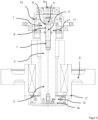
- FIG. 1 A wheel drive for a rail vehicle with a 2-part coupling system is shown.
- FIG. 1 a first coupling half 1, which is designed as a toothed coupling and is connected to a gear (not shown) via the teeth of the drive-side sleeve 13.
- the first coupling half 1 has a first coupling shaft 11, in which a through hole 8 is made centrally and axially.
- the first coupling shaft 11 is arranged axially aligned with the second coupling shaft 12.
- the second coupling shaft 12 is a component of the second coupling half 2 and has a centrally and axially arranged stud bolt 4 on the end area side, which is screwed into the second coupling shaft 12 via the inner thread 7 of the stud bolt 4.
- At the other end of the stud bolt 4 there is an external thread 6, onto which a nut 5 is screwed, thus connecting the two coupling halves 1 and 2 in a force-fitting manner.
- a grounding contact element 10 is connected to both the second coupling half 2 and the wheel 9 of the rail vehicle via the detachable wheel connections 17 as an electrically conductive contact.
- the nut 5 is also loosened and removed from the first coupling half 1 and the stud bolt 4 from the external thread 6, and the wheel connections 17 and the connection of the earthing contact element 10 are loosened from the wheel 9.
- the second coupling half 2 with earthing contact element 10 and stud bolt 4 can now be removed.
- FIG. 2 , 3 and 4 A wheel drive for a rail vehicle with a 3-part coupling system is shown.
- FIG. 2 a clutch system with a clutch half 1, which is designed as a toothed clutch, wherein the toothed clutch is in engagement with a gear (not shown) and the teeth on the front side of a transmission shaft 3.
- the first clutch half 1 has a first clutch shaft 11, in which a through-bore 8 is made centrally and axially.
- the first clutch shaft 11 is arranged axially aligned with the transmission shaft 3 and the second clutch shaft 12.
- the transmission shaft 3 has at its left end a centrally axially arranged stud bolt 4, which is screwed into the transmission shaft 3 via the inner thread 7 of the stud bolt 4. At the other end of the stud bolt 4 there is an external thread 6, onto which a nut 5 is screwed, thus connecting the transmission shaft 3 to the first coupling half 1 in a force-fitting manner.
- the transmission shaft 3 has at its right end another stud bolt 4, which is screwed into the transmission shaft 3 via the inner thread 7 of the stud bolt 4.
- the second clutch shaft 12 is arranged axially aligned with the transmission shaft 3 and the first clutch shaft 11 and is part of the second clutch half 2.
- the second coupling half 2 is designed as a ring disk coupling, which is detachably connected to the transmission shaft 3 by screwing the nut 5 to the stud bolt 4.
- the ring disk coupling is in turn connected to the wheel 9 of the rail vehicle in a force-locking and form-locking manner.
- the closure element 14 is removed from the opening of the sleeve 13 and the nut 5 is loosened and removed from the first coupling half 1 and the stud bolt 4 from the external thread 6 and then the first coupling half 1 is pulled from the stud bolt 4 and removed.
- the nut 5 is loosened from the second coupling half 2 and the stud bolt 4 from the external thread 6 and removed.
- the second coupling half 2 with earthing contact element 10 and stud bolt 4 can then be removed.
- the Fig. 3 and Fig. 4 also show a 3-part clutch system, whereby the second clutch half 2 assigned to the wheel is connected to the transmission shaft 3 via a screw 15 Fig. 3 or with a press bandage 16 according to Fig. 4 is connected.
- the Fig. 5 shows a 3-part coupling system in which the stud bolt 4 is pre-assembled axially in the second coupling half 2 assigned to the wheel.
- the stud bolt 4 extends through a through hole 8 of the aligned transmission shaft 3 and further through the through hole 8 of the first coupling half 1 assigned to the drive.
- the end of the stud bolt protrudes from the first coupling half 1, wherein the force-locking connection of the first coupling half 1, the transmission shaft 3 and the second coupling half 2 is realized by means of a nut 5 screwed onto the outer thread 6 of the stud bolt 4.
- the coupling is assembled in such a way that the stud bolt 4 is pre-assembled into the second coupling half 2 assigned to the wheel in the coupling shaft 12.
- the transmission shaft 3 with the through hole 8 is then pushed onto the stud bolt 4 and then the first coupling half 1 assigned to the drive with the through hole 8 is also pushed onto the stud bolt 4 and the coupling is connected in a force-locking manner using a nut 5.
- the correct fit of the first coupling half 1 and the transmission shaft 3 to the second coupling half 2 is checked using a test gauge through the opening of the drive-side sleeve 13 on the nut 5 and the protruding stud bolt 4. After assembly, the opening of the sleeve 13 is closed using a closure element 14.
Landscapes
- Engineering & Computer Science (AREA)
- Chemical & Material Sciences (AREA)
- Combustion & Propulsion (AREA)
- Transportation (AREA)
- Mechanical Engineering (AREA)
- Arrangement And Mounting Of Devices That Control Transmission Of Motive Force (AREA)
- Mechanical Operated Clutches (AREA)
Description
- Die Erfindung bezieht sich auf das Gebiet der Schienenfahrzeugtechnik und betrifft eine Kupplung für Schienenfahrzeuge. Die erfindungsgemäße Kupplung kann insbesondere bei Schienenfahrzeugen eingesetzt werden, die eine doppelkardanisch wirkende Kupplung zum Ausgleich von axialen, radialen und winkligen Verlagerungen zwischen Getriebe und Rad aufweisen.
- Bekannte Kupplungen für Schienenfahrzeuge werden als Übertragungsmittel eingesetzt, um die von einer Motorwelle ausgehenden Drehmomente über ein Getriebe und eine nachfolgend angeordnete und mit dem Getriebe und dem Rad verbundene Kupplung auf das Rad des Schienenfahrzeuges zu übertragen.
- Aus dem Stand der Technik sind verschiedene Lösungen für derartige Kupplungen bekannt.
- Aus der
EP 1 940 667 A1 ist eine kardanische Doppelgelenkkupplung für Schienenfahrzeuge mit zwei Gelenkebenen bekannt, die zwei Kupplungsgelenke enthält und zur Drehmomentübertragung durch eine Ritzelhohlwelle über eine von der Ritzelhohlwelle umschlossene Welle miteinander verbunden ist. Die eine Gelenkebene ist einem Kupplungsgelenk mit Balligverzahnung mit winkligem und axialem Ausgleichsvermögen zugeordnet und die andere Gelenkebene ist einem drehsteifen, biegeelastischen Kupplungsgelenk zugeordnet. Das Kupplungsgelenk mit Balligverzahnung weist eine tauschbare Hülse mit Innenverzahnung und eine tauschbare Kupplungsnabe mit dazu gehöriger Außenverzahnung auf, wobei die als Zwischenwelle ausgebildete Welle endbereichsseitig mit der tauschbaren Kupplungsnabe verbunden ist und die Ritzelhohlwelle außerhalb der tauschbaren Hülse an der Außenwandung der Hülse befestigt ist. - Auch bekannt aus der
EP 1 197 412 A1 ist eine Antriebseinheit für Schienenfahrzeuge mit einem am Fahrzeugrahmen oder am Fahrwerk aufgehängten Elektromotor, einem Getriebe und einem kardanisch wirkenden Kupplungssystem bekannt, wobei das Kupplungssystem zwischen einer Radsatzwelle und dem Getriebe angeordnet ist. Ein erster Teil des Kupplungssystems ist in Form einer Bogenzahnkupplung in das Abtriebszahnrad des Getriebes und in dessen Schmierölkreislauf integriert. Zwischen Getriebe und Radsatz ist ein abtriebsseitiger zweiter Teil des Kupplungssystems vorgesehen. - Aus der
GB 600 389 - Weiterhin bekannt aus der
EP 2 776 299 B1 ist eine Getriebeeinheit für einen Antrieb eines Rades, insbesondere eines Rades eines Schienenfahrzeuges, mit einem Getriebe, einer Verbindungswelle zur Verbindung von Rad und Getriebe und einem zwischen dem Rad und dem Getriebe vorgesehenen, an der Verbindungswelle angeordneten und kardanisch wirkenden, zweigeteilten Kupplungssystem, wobei die Verbindungswelle durch die hohle Radnabe geführt ist und ein erster Teil eines Kupplungssystems auf der dem Getriebe zugewandten Seite und ein zweiter Teil der dem Getriebe abgewandten Seiten des Rades angeordnet ist, wobei die beiden Teile der Verbindungswelle an der Trennstelle mittels einer Zentralschraube verbunden sind. - Aus der
CN 203 496 892 U ist ein Niederflurfahrzeug-Getriebe und Rad-zu-Rad-Verbindungsstruktur bekannt, bei der die Getriebeausgangswelle eine Hohlwelle mit einem Mittelloch ist und eine Achse oder ein Ende des Rades mit einem Gewindeloch versehen ist und die Hohlwelle fest mit der Achse oder dem Rad durch eine vorgespannte große Schraube verbunden ist, die durch das Mittelloch verläuft. - Nachteilig bei den aus dem Stand der Technik bekannten Lösungen ist, dass die Montage und Demontage derartiger Kupplungen aufwendig ist und bei der Montage Beschädigungen beim Zusammenführen der zu fügenden Kupplungshälften auftreten können. Die aus dem Stand der Technik bekannten Lösungen ermöglichen zudem nur eine unzureichende Genauigkeit bei der Montage der Kupplung. Ein Kontrollmöglichkeit über die korrekte und positionsgenaue Montage ist nicht in einfacher Art und Weise nach dem Stand der Technik möglich.
- Aufgabe der vorliegenden Erfindung ist es, eine mindestens 2-geteilte Kupplung für Schienenfahrzeuge bereitzustellen, die einfach und sicher in der Montage ist, Beschädigungen beim Zusammenbau der Kupplung weitgehend vermeidet und eine hohe Positionsgenauigkeit der gefügten Kupplungshälften aufweist.
- Die Aufgabe wird durch die in den Patentansprüchen angegebene Erfindung gelöst. Vorteilhafte Ausgestaltungen sind Gegenstand der Unteransprüche, wobei die Erfindung auch Kombinationen der einzelnen abhängigen Schutzansprüche im Sinne einer Und-Verknüpfung einschließt, solange sie sich nicht gegenseitig ausschließen.
- Die erfindungsgemäße Lösung betrifft eine Kupplung für Schienenfahrzeuge, enthaltend ein 2-geteiltes Kupplungssystem, das eine einem Antrieb zugewandte erste Kupplungshälfte und eine einem Rad zugewandte zweite Kupplungshälfte aufweist, wobei die erste Kupplungshälfte mit dem Antrieb in Verbindung steht und mindestens eine erste Kupplungswelle und eine antriebsseitige Hülse aufweist, und wobei die zweite Kupplungshälfte mit einem Rad des Schienenfahrzeuges verbunden ist und eine zweite Kupplungswelle aufweist, wobei die zweite Kupplungswelle durch eine hohle Nabe eines Rades geführt ist, und wobei die Trennstelle der ersten und zweiten Kupplungswelle derart realisiert ist, dass an der jeweiligen zueinander gewandten Stirnseite der Kupplungswellen Verzahnungen oder Reibflächen vorhanden sind, die mindestens kraft- und/oder formschlüssig mindestens ein Drehmoment übertragen, wobei ein zentrisch axial in der zweiten Kupplungswelle angeordneter vormontierter Stehbolzen mindestens zum Ausrichten, Zentrieren, Führen und Prüfen der zweiten Kupplungshälfte zur ersten Kupplungshälfte vorhanden ist, wobei der Stehbolzen innerhalb einer zentrisch axialen Durchgangsbohrung angeordnet ist, die in der erste Kupplungswelle vorhanden ist, und wobei der Stehbolzen an der von der Stirnseite der ersten Kupplungswelle abgewandten Seite aus der ersten Kupplungshälfte mit einem Bereich herausragt, wobei der Stehbolzen mindestens in diesem herausragenden Bereich ein äußeres Gewinde aufweist, auf das eine Mutter geschraubt ist, mit der mindestens eine kraftschlüssige Verbindung der ersten Kupplungshälfte und der zweiten Kupplungshälfte realisiert ist.
- Die erfindungsgemäße Lösung betrifft auch eine Kupplung für Schienenfahrzeuge, enthaltend ein 3-geteiltes Kupplungssystem, das eine einem Antrieb zugewandte erste Kupplungshälfte und eine einem Rad zugewandte zweite Kupplungshälfte und eine Übertragungswelle aufweist, wobei die erste Kupplungshälfte mit dem Antrieb in Verbindung steht und mindestens eine erste Kupplungswelle und eine antriebsseitige Hülse aufweist, und wobei die zweite Kupplungshälfte mit einem Rad des Schienenfahrzeuges verbunden ist und eine zweite Kupplungswelle aufweist, wobei die zweite Kupplungswelle durch eine hohle Nabe eines Rades geführt ist, und wobei die Trennstelle der ersten und zweiten Kupplungswelle mit der Übertragungswelle derart realisiert ist, dass an der jeweiligen zueinander gewandten Stirnseite der Kupplungswellen und der Übertragungswelle Verzahnungen und/oder Reibflächen vorhanden sind, mit denen mindestens kraft-, und/oder formschlüssig ein Drehmoment übertragbar ist, wobei zwischen den Kupplungswellen der ersten und zweiten Kupplungshälften axial fluchtend eine Übertragungswelle angeordnet ist, die von der ersten und/oder zweiten Kupplungshälfte lösbar verbunden ist, und wobei mindestens ein zentrisch axial in der Übertragungswelle angeordneter vormontierter Stehbolzen mindestens zum Ausrichten, Zentrieren, Führen und Prüfen mindestens der Übertragungswelle und der zweiten Kupplungshälfte zur ersten Kupplungshälfte vorhanden ist, wobei der Stehbolzen innerhalb einer zentrisch axialen Durchgangsbohrung angeordnet ist, die mindestens in der ersten Kupplungswelle vorhanden ist, und wobei der Stehbolzen an der von der Stirnseite der ersten Kupplungswelle abgewandten Seite aus der ersten Kupplungshälfte mit einem Bereich herausragt, wobei der Stehbolzen mindestens in diesem herausragenden Bereich ein äußeres Gewinde aufweist, auf das eine Mutter geschraubt ist, mit der mindestens eine kraftschlüssige Verbindung mindestens der ersten Kupplungshälfte und der Übertragungswelle realisiert ist.
- Vorteilhafterweise ist die erste Kupplungshälfte eine Zahnkupplung und/oder die von der Übertragungswelle lösbare zweite Kupplungshälfte eine Zahnkupplung, eine Ringscheibenkupplung, eine Keilpaketringkupplung, ein Keilpaket, eine Laschenkupplung oder eine Lenkerkupplung ist.
- Auch vorteilhafterweise ist die Verbindung der Übertragungswelle mit der ersten und/oder der zweiten Kupplungshälfte mittels Stirnverzahnung, Planverzahnung, Pressverband und/oder Flanschverschraubung realisiert.
- Vorteilhaft ist auch, wenn zwei zentrisch axial angeordnete Stehbolzen in der Übertragungswelle endbereichsseitig vormontiert sind.
- In einer besonders vorteilhaften Ausführung der Erfindung ist ein vormontierter Stehbolzen in der zweiten Kupplungswelle zentrisch axial angeordnet, der sich durch eine Durchgangsbohrung der Übertragungswelle und eine Durchgangsbohrung der ersten Kupplungshälfte erstreckt und aus der ersten Kupplungshälfte herausragt.
- Zudem ist vorteilhaft, wenn der mindestens eine Stehbolzen eingeschraubt, eingeklebt und/oder mittels einer Presspassung vormontiert ist.
- Besonders vorteilhaft ist es, wenn die Passung von Durchgangsbohrung und Stehbolzen als Gleitpassung oder Schiebepassung ausgeführt ist.
- Außerdem ist es vorteilhaft, wenn die Verbindung von Übertragungswelle und zweiter Kupplungswelle der dem Rad zugewandten zweiten Kupplungshälfte mittels eines Stehbolzens, einer radseitigen Schraube oder einem Pressverband realisiert ist.
- In einer vorteilhaften Ausführung weist die antriebsseitige Hülse eine Öffnung mit einem Verschlusselement auf, wobei besonders vorteilhaft das Verschlusselement ein Verschlussstopfen oder eine Verschlussschraube ist.
- In einer weiteren vorteilhaften Ausführung der Kupplung steht die erste Kupplungshälfte mit einem Getriebe oder direkt mit einem Motor in Verbindung steht.
- Und auch vorteilhafterweise ist bei der Kupplung die Anbindung der zweiten Kupplungshälfte an das Rad und/oder das Erdungskontaktelement form-, kraft- oder stoffschlüssig realisiert.
- Mit der vorliegenden Erfindung wird eine Kupplung für Schienenfahrzeuge bereitgestellt, die als 2-geteiltes oder 3-geteiltes Kupplungssystem ausgeführt ist und sich insbesondere durch eine einfache, kostengünstige und sichere Montage auszeichnet. Zudem ermöglicht die erfindungsgemäße Kupplung eine schnelle und kostengünstige Wartung und Instandsetzung sowie im Fall eines 3-geteilten Kupplungssystems durch die vereinfachte Fertigung der Einzelteile eine schnelle Anpassung an verschiedene Spurbreiten unterschiedlicher Schienensysteme.
- Erreicht wird dies durch eine Kupplung für Schienenfahrzeuge, bei der in einem 2-geteilten Kupplungssystem in der Kupplungswelle der zweiten Kupplungshälfte ein zentrisch axial angeordneter Stehbolzen vormontiert ist. Der zentrisch axial vormontierte Stehbolzen ist mit seinem einen Ende in der Kupplungswelle der zweiten Kupplungshälfte eingebracht und kann dort beispielsweise kraftschlüssig eingeschraubt, formschlüssig arretiert und/oder stoffschlüssig eingeklebt sein. Das andere Ende des Stehbolzens ist durch eine Durchgangsbohrung, die zentrisch axial in der Kupplungswelle der ersten Kupplungshälfte eingebracht ist, vollständig durchgeführt und ragt aus der ersten Kupplungshälfte heraus. Mindestens der herausragende Bereich des Stehbolzens ist mit einem äußeren Gewinde versehen, auf das eine Mutter aufgeschraubt ist, mit der die beiden Kupplungshälften bei einem 2-geteilten Kupplungssystem verbunden werden.
- Mindestens ein erfindungsgemäßer Stehbolzen kommt auch bei dem erfindungsgemäßen 3-geteiltem Kupplungssystem zum Einsatz. Bei einem 3-geteiltem Kupplungssystem ist zwischen der dem Antrieb zugeordneten ersten Kupplungshälfte und der dem Rad zugeordneten zweiten Kupplungshälfte axial fluchtend eine Übertragungswelle angeordnet, in die ein oder beidseitig endseitig und zentrisch axial mindestens ein Stehbolzen vormontiert ist.
- Mit dem mindestens einen vormontierten Stehbolzen werden mehrere Vorteile und technische Wirkungen gegenüber den aus dem Stand der Technik bekannten Lösungen erreicht.
- Einerseits stellt der erfindungsgemäße Stehbolzen eine einfache und wirkungsvolle Montagehilfe zum Ausrichten der beiden Kupplungshälften beim Zusammenführen der ersten und zweiten Kupplungshälfte dar. Eine Beschädigung durch ein Aneinanderstoßen an den korrespondierenden Verzahnungen, die an den Stirnseiten der ersten und zweiten Kupplungswelle oder an der Stirnseite der Übertragungswelle an der Trennstelle der beiden Kupplungshälften vorhanden sind, wird damit wirksam und in einfacher Weise vermieden.
- Ein weiterer Vorteil besteht darin, dass der erfindungsgemäße Stehbolzen eine Zentrier- und Führungshilfe zum Finden der zentrischen Position und zum kontrollierten Zusammenführen der beiden Kupplungshälften ist. Damit wird erreicht, dass beim Zusammenbau der beiden Kupplungshälften der Stehbolzen in die Öffnung der vorgefertigten Durchgangsbohrung der ersten Kupplungshälfte in einfacher Weise einführbar ist und durch das nachfolgende Führen des Stehbolzens durch die in der dem Antrieb zugeordneten ersten Kupplungshälfte, mit der in der ersten Kupplungswelle bereits vorhandenen Durchgangsbohrung eine definierte translatorische Bewegung beim Zusammenführen der beiden Kupplungshälften realisiert wird.
- Vorteilhafterweise weist der Stehbolzen an dem Ende, das in die Durchgangsbohrung der ersten oder zweiten Kupplungswelle eingeführt wird, einen sich zum Ende des Stehbolzens verjüngen Abschnitt auf, um das beschädigungsfreie Einführen des Stehbolzen in die Durchgangsbohrung bei der Montage der Kupplung zu erleichtern.
- Ein weiterer technischer Vorteil besteht darin, dass mit dem erfindungsgemäßen Stehbolzen der korrekte und positionsgenaue Zusammenbau der beiden Kupplungshälften geprüft werden kann. So ist es möglich, anhand eines festgelegten Prüfmaßes mittels beispielsweise einer Prüflehre den korrekten Sitz der ersten und zweiten Kupplungshälfte durch Messung des herausragenden Überstandes des Stehbolzens oder dem Sitz der Mutter auf dem Stehbolzen durch die Öffnung der antriebsseitigen Hülse zu messen und gegebenenfalls die Position der Kupplungshälften zueinander zu korrigieren.
- Nach dem korrekten und positionsgenauen Zusammenbau sind die beiden Kupplungshälften mittels einer Mutter über das äußere Gewinde, das sich am Ende des aus der ersten Kupplungshälfte herausragenden Stehbolzens befindet, verschraubt. Die Trennung der beiden Kupplungshälften erfolgt in einfacher Art und Weise durch das Lösen und Entfernen der Mutter vom erfindungsgemäßen Stehbolzen mittels Werkzeug, dass durch die Öffnung der Hülse einführbar ist.
- Für ein besonders genaues Zusammenführen der beiden Kupplungshälften ist es von Vorteil, wenn die Passung des Stehbolzens und der Durchgangsbohrung als Gleitpassung oder Schiebepassung ausgeführt ist. Eine Gleitpassung oder Schiebepassung von Durchgangsbohrung und Stehbolzen ermöglicht ein sicheres, genaues und schnelles Einführen des Stehbolzens in die Durchgangsbohrung der ersten Kupplungshälfte bei geringem Kraftaufwand durch die geringe Reibung des Stehbolzens in der Durchgangsbohrung beim Zusammenführen der Kupplungshälften. Zudem wird mit der vorteilhaften Passung erreicht, dass bereits bei der Montage der ersten und zweiten Kupplungshälften eine hohe axiale Positionsgenauigkeit erreicht wird, die ein aufwendiges axiales Nachjustieren der beiden Kupplungshälften vermeidet.
- Erfindungsgemäß kann das Kupplungssystem zwischen der dem Antrieb zugewandten ersten Kupplungshälfte und der dem Rad zugewandten zweiten Kupplungshälfte eine zur ersten und zweiten Kupplungswelle axial fluchtend angeordnete Übertragungswelle aufweisen. Die erste und die zweite Kupplungshälfte sind dabei jeweils mit der Übertragungswelle über eine lösbare Verbindung verbunden.
- Die Verbindung der Übertragungswelle mit der dem Antrieb zugeordneten ersten Kupplungshälfte ist erfindungsgemäß stets über den zentrisch axial in der Übertragungswelle vormontierten Stehbolzen realisiert, der bei der Montage der Kupplung durch die zentrisch axial eingebrachte Durchgangsbohrung in der ersten Kupplungshälfte geführt ist und an dessen Ende mit einer Mutter verschraubt ist.
- Die Verbindung der Übertragungswelle mit der dem Rad zugeordneten zweiten Kupplungshälfte kann vorteilhafterweise verschiedenen ausgestaltet sein. So ist es möglich, dass die Verbindung ebenfalls mittels eines Stehbolzens, der bereits im Endbereich der Übertragungswelle vormontiert ist, realisiert ist. Die Verschraubung der zweiten Kupplungshälfte erfolgt wie auf der Antriebsseite mit einer Mutter, die auf das Außengewinde des Stehbolzens geschraubt wird.
- Möglich ist aber auch, dass die Verbindung von Übertragungswelle und zweiter Kupplungshälfte durch eine radseitig zugeführte Schraube oder durch einen Pressverband realisiert ist.
- Durch die lösbaren Verbindungen an den beiden Enden der Übertragungswelle mit der ersten und zweiten Kupplungshälfte wird erreicht, dass im Fall des Verschleißes einer oder beider Kupplungshälften diese unabhängig von der Übertragungswelle ersetzt werden können. Die führt zur Einsparung von Wartungs- und Instandhaltungskosten, da nur das oder die Kupplungshälften ersetzt werden müssen, die tatsächlich verschlissen sind. Der Ausbau und Austausch der Übertragungswelle aus der hohlen Radnabe des Rades ist damit nicht erforderlich.
- Ein weiterer Vorteil lösbarer Verbindungen zwischen Übertragungswelle und der ersten und zweiten Kupplungshälfte besteht darin, dass das 3-geteilte Kupplungssystem durch die variable Anpassung der Länge der Übertragungswelle für verschiedene Spurweiten unterschiedlicher regionaler Schienensysteme einfach und kostengünstig adaptiert werden kann.
- Zudem ermöglicht das 3-geteilte Kupplungssystem, dass die dem Antrieb zugeordnete erste Kupplungshälfte und die dem Rad zugeordnete zweite Kupplungshälfte in deren Ausführung und Funktion variabel miteinander kombiniert werden kann, wodurch der Einsatz der Kupplung variabel auf die gewünschten Anwendungen angepasst werden kann. So ist es beispielsweise möglich, dass die dem Antrieb zugeordnete erste Kupplungshälfte als Zahnkupplung und die dem Rad zugeordnete zweite Kupplungshälfte als Ringscheibenkupplung, Keilpaketringkupplung, Keilpaket Laschenkupplung, Lenkerkupplung oder ebenfalls als Zahnkupplung ausgebildet ist. Dies ermöglicht ein breites Anwendungsspektrum der erfindungsgemäßen Kupplung.
- Ein weiterer Vorteil einer 3-teilig ausgebildeten Kupplung ist, dass die Herstellungskosten gegenüber beispielsweise einer 2-teilig ausgebildeten Kupplung gesenkt werden können. So ist es möglich, kostengünstigeres Material für die Herstellung der geringer beanspruchten Übertragungswelle zu verwenden, wodurch der Materialaufwand gegenüber herkömmlich 2-teilig ausgebildeten Kupplungen verringert werden kann.
- Vorteilhafterweise ist die Drehmomentübertragung von der ersten Kupplungshälfte zu Übertragungswelle und/oder Übertragungswelle zur zweiten Kupplungshälfte über eine Stirnverzahnung, Planverzahnung, eine Rändelung, einen Pressverband und/oder eine Flanschverschraubung realisiert. Dadurch wird eine sichere Drehmomentübertragung von der einem Antrieb zugeordneten ersten Kupplungshälfte über die Übertragungswelle auf die dem Rad zugeordneten zweiten Kupplungshälfte sichergestellt.
- In einer vorteilhaften Ausgestaltung der ersten oder zweiten Kupplungshälfte weist die Hülse eine Öffnung mit einem Verschlusselement für eine einfache Montage und Demontage der Kupplung auf. Die Öffnung ist derart ausgebildet, das sie axial fluchtend zu den Kupplungswellen und der Übertragungswelle angeordnet ist, sodass ein passendes Werkzeug zum Lösen oder Festziehen der auf dem Stehbolzen befindlichen Mutter eingeführt und eingesetzt werden kann. Die Öffnung ermöglicht zudem das kontrollierte Einbringen von Schmierstoff, das Nachschmieren der Kupplungsverzahnung und die Schmierstoffkontrolle.
- Zudem weist die Öffnung der Hülse ein herausnehmbares Verschlusselement auf. Das Verschlusselement kann dabei ein Verschlussstopfen oder eine Verschlussschraube sein, die die Kupplung vor Staub und Schmutz schützt.
- In einer besonders vorteilhaften Ausgestaltung der Kupplung ist die erste Kupplungshälfte direkt mit einem Motor ohne Getriebe verbunden. Die direkte Verbindung der ersten Kupplungshälfte mit einem Motor hat den Vorteil, dass der gesamte Antrieb mit erfindungsgemäßem Kupplungssystem kostengünstiger und leichter ausgeführt ist. Eine Getriebeeinheit wird dadurch nicht benötigt.
- Möglich ist aber auch, dass die antriebsseitige erste Kupplungshälfte über eine Verzahnung der Hülse mit einem Getriebe verbunden ist.
- Zusammenfassend werden die besonderen Vorteile und technischen Wirkungen der erfindungsgemäße Kupplung darin gesehen, dass mit dem Einsatz eines vormontierten Stehbolzens in der zweiten Kupplungshälfte und/oder in der Übertragungswelle eine sichere, kosten- und zeitsparende Montage der Kupplung bei Vermeidung von Schäden beim Zusammenführen der Kupplungshälften ermöglicht wird. Zudem wird mit dem Einsatz eines oder zweier Stehbolzen eine einfache Lösung zum Vorzentrieren und kontrollierten Führen der Kupplungshälften erreicht. Ein weitere wesentlicher Vorteil besteht darin, dass mit Hilfe des aus der oder den Kupplungshälften herausstehenden Endes des oder der Stehbolzen ein Prüfmaß zur Verfügung steht, mit dem der korrekte Sitz und die korrekte Position der Kupplungshälfte gemessen und ermittelt werden kann und gegebenenfalls noch Korrekturen vor der Endmontage der Kupplung vorgenommen werden können. Eine aus dem Stand der Technik bisher bekannte und nachteilige Blindmontage der beiden Kupplungshälften entfällt mit der erfindungsgemäßen Lösung. Zudem bietet ein 3-geteilte Kupplungssystem die Möglichkeit, die Kupplung durch einfachen und zeitsparenden Austausch der Übertragungswelle auf verschiedene Spurweiten von Schienenfahrzeugen anzupassen.
- Nachfolgend wird die Erfindung anhand von drei Ausführungsbeispielen näher erläutert. Dabei zeigen
- Fig. 1
- eine schematische Schnittdarstellung des erfindungsgemäßen 2-geteilten Kupplungssystems mit einem in der zweiten Kupplungshälfte angeordneten Stehbolzen,
- Fig. 2
- eine schematische Schnittdarstellung eines 3-geteilten Kupplungssystems mit beidseitiger Stehbolzenverbindung in der Übertragungswelle,
- Fig. 3
- eine schematische Schnittdarstellung eines 3-geteilten Kupplungssystems mit antriebsseitiger Stehbolzenverbindung und radseitiger Schraubverbindung,
- Fig. 4
- eine schematische Schnittdarstellung eines 3-geteilten Kupplungssystems mit antriebsseitiger Stehbolzenverbindung und radseitigem Pressverband und
- Fig. 5
- eine schematische Schnittdarstellung eines 3-geteilten Kupplungssystems mit einer Stehbolzenverbindung
- Gemäß
Fig. 1 ist ein Radantrieb für ein Schienenfahrzeug mit einem 2-geteilten Kupplungssystem dargestellt. - Dabei zeigt
Fig. 1 eine erste Kupplungshälfte 1, die als Zahnkupplung ausgebildet ist und mit einem Getriebe (nicht dargestellt) über die Verzahnung der antriebsseitigen Hülse 13 in Verbindung steht. Die erste Kupplungshälfte 1 weist eine erste Kupplungswelle 11 auf, in der zentrisch axial eine Durchgangsbohrung 8 eingebracht ist. Die erste Kupplungswelle 11 ist axial fluchtend zur zweiten Kupplungswelle 12 angeordnet. Die zweite Kupplungswelle 12 ist ein Bestandteil der zweiten Kupplungshälfte 2 und weist endbereichsseitig einen zentrisch axial angeordneten Stehbolzen 4 auf, der in die zweite Kupplungswelle 12 über das innere Gewinde 7 des Stehbolzens 4 eingeschraubt ist. Am anderen Ende des Stehbolzens 4 ist ein äußeres Gewinde 6 vorhanden, auf das eine Mutter 5 aufgeschraubt ist und so die beiden Kupplungshälften 1 und 2 kraftschlüssig verbindet. - Ein Erdungskontaktelement 10 ist sowohl mit der zweiten Kupplungshälfte 2 als auch mit dem Rad 9 des Schienenfahrzeuges über die lösbaren Radanbindungen 17 als elektrisch leitender Kontakt verbunden.
- Im Falle des Verschleißes beispielsweise der ersten Zahnkupplungshälfte 1 wird zum Austausch das Verschlusselement 14 aus der Öffnung der Hülse 13 entfernt und die Mutter 5 von der ersten Kupplungshälfte 1 und dem Stehbolzen 4 vom äußeren Gewinde 6 gelöst und entfernt und anschließend die erste Kupplungshälfte 1 vom Stehbolzen 4 gezogen und entnommen.
- Im Falle des Verschleißes der zweiten Kupplungshälfte 2 der Zahnkupplung wird ebenfalls die Mutter 5 von der ersten Kupplungshälfte 1 und dem Stehbolzen 4 vom äußeren Gewinde 6 gelöst und entfernt sowie die Radanbindungen 17 und die Verbindung des Erdungskontaktelementes 10 vom Rad 9 gelöst. Die zweite Kupplungshälfte 2 mit Erdungskontaktelement 10 und Stehbolzen 4 kann nunmehr entnommen werden.
- Gemäß den
Fig. 2 ,3 und4 ist ein Radantrieb für ein Schienenfahrzeug mit einem 3-geteilten Kupplungssystem dargestellt. - Dabei zeigt
Fig. 2 ein Kupplungssystem mit einer Kupplungshälfte 1, die als Zahnkupplung ausgebildet ist, wobei die Zahnkupplung mit einem Getriebe (nicht dargestellt) und der Verzahnung an der Stirnseite einer Übertragungswelle 3 im Eingriff steht. Die erste Kupplungshälfte 1 weist eine erste Kupplungswelle 11 auf, in der zentrisch axial eine Durchgangsbohrung 8 eingebracht ist. Die erste Kupplungswelle 11 ist axial fluchtend zur Übertragungswelle 3 und der zweiten Kupplungswelle 12 angeordnet. - Die Übertragungswelle 3 weist an seinem linken Ende einen zentrisch axial angeordneten Stehbolzen 4 auf, der in die Übertragungswelle 3 über das innere Gewinde 7 des Stehbolzens 4 eingeschraubt ist. Am anderen Ende des Stehbolzens 4 ist ein äußeres Gewinde 6 vorhanden, auf das eine Mutter 5 aufgeschraubt ist und so die Übertragungswelle 3 mit der ersten Kupplungshälfte 1 kraftschlüssig verbindet.
- Die Übertragungswelle 3 weist an seinem rechten Ende einen weiteren Stehbolzen 4 auf, der in die Übertragungswelle 3 über das innere Gewinde 7 des Stehbolzens 4 eingeschraubt ist. Am Ende des rechtsseitig angeordneten Stehbolzens 7 ist ein äußeres Gewinde 6 vorhanden, auf das eine Mutter 5 aufgeschraubt ist, wobei der rechtsseitige Stehbolzen 4 durch eine zentrisch axial angeordnete Durchgangsbohrung 8 der zweiten Kupplungswelle 12 geführt ist und aus der zweiten Kupplungshälfte 2 mit seinem äußeren Gewinde 6 herausragt.
- Die zweite Kupplungswelle 12 ist axial fluchtend zur Übertragungswelle 3 und der ersten Kupplungswelle 11 angeordnet und Bestandteil der zweiten Kupplungshälfte 2.
- Die zweite Kupplungshälfte 2 ist als Ringscheibenkupplung ausgebildet, die lösbar mit der Übertragungswelle 3 über die Verschraubung der Mutter 5 mit dem Stehbolzen 4 verbunden ist. Die Ringscheibenkupplung ist wiederum mit dem Rad 9 des Schienenfahrzeuges kraft- und formschlüssig verbunden.
- Im Falle des Verschleißes und Austausches beispielsweise der ersten Kupplungshälfte 1 wird das Verschlusselement 14 aus der Öffnung der Hülse 13 entfernt und die Mutter 5 von der ersten Kupplungshälfte 1 und dem Stehbolzen 4 vom äußeren Gewinde 6 gelöst und entfernt und anschließend die erste Kupplungshälfte 1 vom Stehbolzen 4 gezogen und entnommen.
- Im Falle des Verschleißes der zweiten Kupplungshälfte 2 wird die Mutter 5 von der zweiten Kupplungshälfte 2 und dem Stehbolzen 4 vom äußeren Gewinde 6 gelöst und entfernt. Die zweite Kupplungshälfte 2 mit Erdungskontaktelement 10 und Stehbolzen 4 kann dann entnommen werden.
- Im Falle des Austausches einer oder beider Kupplungshälften 1 und/oder 2 kann die Übertragungswelle 3 in der Radnabe des Rades 9 verbleiben und steht für die anschließende Verbindung mit den neuen Kupplungshälften zur Verfügung.
- Die
Fig. 3 undFig. 4 zeigen ebenfalls ein 3-geteiltes Kupplungssystem, wobei die dem Rad zugeordnete zweite Kupplungshälfte 2 mit der Übertragungswelle 3 über eine Schraube 15 nachFig. 3 beziehungsweise mit einem Pressverband 16 nachFig. 4 verbunden ist. - Die
Fig. 5 zeigt ein 3-geteiltes Kupplungssystem, bei dem der Stehbolzen 4 in der dem Rad zugeordneten zweiten Kupplungshälfte 2 zentrisch axial vormontiert ist. In diesem Fall erstreckt sich der Stehbolzen 4 durch eine Durchgangsbohrung 8 der fluchtend angeordneten Übertragungswelle 3 und weiter durch die Durchgangsbohrung 8 der dem Antrieb zugeordneten ersten Kupplungshälfte 1. Das Ende des Stehbolzens ragt aus der ersten Kupplungshälfte 1 heraus, wobei die kraftschlüssige Verbindung der ersten Kupplungshälfte 1, der Übertragungswelle 3 und der zweiten Kupplungshälfte 2 mittels einer auf dem äußeren Gewinde 6 des Stehbolzens 4 aufgeschraubten Mutter 5 realisiert ist. - Die Montage der Kupplung erfolgt in der Weise, dass in die dem Rad zugeordnete zweite Kupplungshälfte 2 in die Kupplungswelle 12 der Stehbolzen 4 vormontiert wird. Anschließend wird die Übertragungswelle 3 mit der Durchgangsbohrung 8 auf den Stehbolzen 4 aufgeschoben und danach die dem Antrieb zugeordnete erste Kupplungshälfte 1 mit der Durchgangsbohrung 8 ebenfalls auf den Stehbolzen 4 aufgeschoben und die Kupplung mittels Mutter 5 kraftschlüssig verbunden. Der korrekte Sitz der ersten Kupplungshälfte 1 und der Übertragungswelle 3 zur zweiten Kupplungshälfte 2 wird mittels einer Prüflehre durch die Öffnung der antriebsseitigen Hülse 13 an der Mutter 5 und dem herausragenden Stehbolzen 4 geprüft. Nach erfolgter Montage wird die Öffnung der Hülse 13 mittels Verschlusselement 14 verschlossen.
-
- 1
- Erste Kupplungshälfte
- 2
- Zweite Kupplungshälfte
- 3
- Übertragungswelle
- 4
- Stehbolzen
- 5
- Mutter
- 6
- Äußeres Gewinde des Stehbolzens
- 7
- Inneres Gewinde des Stehbolzens
- 8
- Durchgangsbohrung
- 9
- Rad
- 10
- Erdungskontaktelement
- 11
- Erste Kupplungswelle
- 12
- Zweite Kupplungswelle
- 13
- Antriebsseitige Hülse
- 14
- Verschlusselement
- 15
- Radseitige Schraube
- 16
- Pressverband
- 17
- Radanbindung
Claims (13)
- Kupplung für Schienenfahrzeuge, enthaltend ein 2-geteiltes Kupplungssystem, das eine einem Antrieb zugewandte erste Kupplungshälfte (1) und eine einem Rad (9) eines Schienenfahrzeuges zugewandte zweite Kupplungshälfte (2) aufweist, wobei die erste Kupplungshälfte (1) mit dem Antrieb in Verbindung steht und mindestens eine erste Kupplungswelle (11) und eine antriebsseitige Hülse (13) aufweist, und wobei die zweite Kupplungshälfte (2) mit dem Rad (9) des Schienenfahrzeuges verbunden ist und eine zweite Kupplungswelle (12) aufweist, wobei die zweite Kupplungswelle (12) durch eine hohle Nabe des Rades (9) geführt ist, und wobei die Trennstelle der ersten und zweiten Kupplungswelle (11, 12) derart realisiert ist, dass an der jeweiligen zueinander gewandten Stirnseite der Kupplungswellen (11, 12) Verzahnungen oder Reibflächen vorhanden sind, die mindestens kraft- und/oder formschlüssig mindestens ein Drehmoment übertragen,
dadurch gekennzeichnet, dass
ein zentrisch axial in der zweiten Kupplungswelle (12) angeordneter vormontierter Stehbolzen (4) mindestens zum Ausrichten, Zentrieren, Führen und Prüfen der zweiten Kupplungshälfte (2) zur ersten Kupplungshälfte (1) vorhanden ist, wobei der Stehbolzen (4) innerhalb einer zentrisch axialen Durchgangsbohrung (8) angeordnet ist, die in der erste Kupplungswelle (11) vorhanden ist, und wobei der Stehbolzen (4) an der von der Stirnseite der ersten Kupplungswelle (11) abgewandten Seite aus der ersten Kupplungshälfte (1) mit einem Bereich herausragt, wobei der Stehbolzen (4) mindestens in diesem herausragenden Bereich ein äußeres Gewinde (6) aufweist, auf das eine Mutter (5) geschraubt ist, mit der mindestens eine kraftschlüssige Verbindung der ersten Kupplungshälfte (1) und der zweiten Kupplungshälfte (2) realisiert ist. - Kupplung für Schienenfahrzeuge, enthaltend ein 3-geteiltes Kupplungssystem, das eine einem Antrieb zugewandte erste Kupplungshälfte (1) und eine einem Rad zugewandte zweite Kupplungshälfte (2) und eine Übertragungswelle (3) aufweist, wobei die erste Kupplungshälfte (1) mit dem Antrieb in Verbindung steht und mindestens eine erste Kupplungswelle (11) und eine antriebsseitige Hülse (13) aufweist, und wobei die zweite Kupplungshälfte (2) mit einem Rad (9) des Schienenfahrzeuges verbunden ist und eine zweite Kupplungswelle (12) aufweist, wobei die zweite Kupplungswelle (12) durch eine hohle Nabe eines Rades (9) geführt ist, und wobei die Trennstelle der ersten und zweiten Kupplungswelle (11, 12) mit der Übertragungswelle (3) derart realisiert ist, dass an der jeweiligen zueinander gewandten Stirnseite der Kupplungswellen (11, 12) und der Übertragungswelle (3) Verzahnungen und/oder Reibflächen vorhanden sind, mit denen mindestens kraft-, und/oder formschlüssig ein Drehmoment übertragbar ist, wobei zwischen den Kupplungswellen (11, 12) der ersten und zweiten Kupplungshälften (1, 2) axial fluchtend eine Übertragungswelle (3) angeordnet ist, die von der ersten und/oder zweiten Kupplungshälfte (1, 2) lösbar verbunden ist,
dadurch gekennzeichnet, dass
mindestens ein zentrisch axial in der Übertragungswelle (3) angeordneter vormontierter Stehbolzen (4) mindestens zum Ausrichten, Zentrieren, Führen und Prüfen mindestens der Übertragungswelle und der zweiten Kupplungshälfte (2) zur ersten Kupplungshälfte (1) vorhanden ist, wobei der Stehbolzen (4) innerhalb einer zentrisch axialen Durchgangsbohrung (8) angeordnet ist, die mindestens in der ersten Kupplungswelle (11) vorhanden ist, und wobei der Stehbolzen (4) an der von der Stirnseite der ersten Kupplungswelle (11) abgewandten Seite aus der ersten Kupplungshälfte (1) mit einem Bereich herausragt, wobei der Stehbolzen (4) mindestens in diesem herausragenden Bereich ein äußeres Gewinde (6) aufweist, auf das eine Mutter (5) geschraubt ist, mit der mindestens eine kraftschlüssige Verbindung mindestens der ersten Kupplungshälfte (1) und der Übertragungswelle (3) realisiert ist. - Kupplung nach Anspruch 1 oder 2, bei der die erste Kupplungshälfte (1) eine Zahnkupplung ist und/oder die von der Übertragungswelle (3) lösbare zweite Kupplungshälfte (2) eine Zahnkupplung, eine Ringscheibenkupplung, eine Keilpaketringkupplung, ein Keilpaket, eine Laschenkupplung oder eine Lenkerkupplung ist.
- Kupplung nach Anspruch 2 oder 3, bei der die Verbindung der Übertragungswelle (3) mit der ersten und/oder der zweiten Kupplungshälfte (1, 2) mittels Stirnverzahnung, Planverzahnung, Pressverband und/oder Flanschverschraubung realisiert ist.
- Kupplung nach mindestens einem der Ansprüche 2 bis 4, bei der zwei zentrisch axial angeordnete Stehbolzen (4) in der Übertragungswelle (3) endbereichsseitig vormontiert sind.
- Kupplung nach mindestens einem der Ansprüche 2 bis 4, bei der ein vormontierter Stehbolzen (4) in der zweiten Kupplungswelle (12) zentrisch axial angeordnet ist, der sich durch eine Durchgangsbohrung (8) der Übertragungswelle (3) und eine Durchgangsbohrung (8) der ersten Kupplungshälfte (1) erstreckt und aus der ersten Kupplungshälfte (1) herausragt.
- Kupplung nach mindestens einem der vorhergehenden Ansprüche, bei der der mindestens eine Stehbolzen (4) eingeschraubt, eingeklebt und/oder mittels einer Presspassung vormontiert ist.
- Kupplung nach mindestens einem der vorhergehenden Ansprüche, bei der die Passung von Durchgangsbohrung (8) und Stehbolzen (4) als Gleitpassung oder Schiebepassung ausgeführt ist.
- Kupplung nach mindestens einem der Ansprüche 2 und 4 bis 6, bei der die Verbindung von Übertragungswelle (3) und zweiter Kupplungswelle (12) der dem Rad (9) zugewandten zweiten Kupplungshälfte (2) mittels eines Stehbolzens (4), einer radseitigen Schraube (15) oder einem Pressverband (16) realisiert ist.
- Kupplung nach mindestens einem der vorhergehenden Ansprüche, bei der die antriebsseitige Hülse (13) eine Öffnung mit einem Verschlusselement (14) aufweist.
- Kupplung nach Anspruch 10, bei dem das Verschlusselement (14) ein Verschlussstopfen oder eine Verschlussschraube ist.
- Kupplung nach mindestens einem der vorhergehenden Ansprüche, bei der die erste Kupplungshälfte (1) mit einem Getriebe oder direkt mit einem Motor in Verbindung steht.
- Kupplung nach mindestens einem der vorhergehenden Ansprüche, bei der die Anbindung der zweiten Kupplungshälfte (12) an das Rad (9) und/oder an ein Erdungskontaktelement (10) form-, kraft- oder stoffschlüssig realisiert ist.
Applications Claiming Priority (2)
| Application Number | Priority Date | Filing Date | Title |
|---|---|---|---|
| DE202019105391.7U DE202019105391U1 (de) | 2019-09-27 | 2019-09-27 | Kupplung für Schienenfahrzeuge |
| PCT/EP2020/076669 WO2021058629A1 (de) | 2019-09-27 | 2020-09-24 | Kupplung für schienenfahrzeuge |
Publications (3)
| Publication Number | Publication Date |
|---|---|
| EP4034445A1 EP4034445A1 (de) | 2022-08-03 |
| EP4034445C0 EP4034445C0 (de) | 2025-01-08 |
| EP4034445B1 true EP4034445B1 (de) | 2025-01-08 |
Family
ID=68419526
Family Applications (1)
| Application Number | Title | Priority Date | Filing Date |
|---|---|---|---|
| EP20780652.2A Active EP4034445B1 (de) | 2019-09-27 | 2020-09-24 | Kupplung für schienenfahrzeuge |
Country Status (6)
| Country | Link |
|---|---|
| EP (1) | EP4034445B1 (de) |
| CN (1) | CN114728665B (de) |
| DE (1) | DE202019105391U1 (de) |
| ES (1) | ES3015459T3 (de) |
| PL (1) | PL4034445T3 (de) |
| WO (1) | WO2021058629A1 (de) |
Family Cites Families (20)
| Publication number | Priority date | Publication date | Assignee | Title |
|---|---|---|---|---|
| FR916946A (fr) | 1944-11-20 | 1946-12-19 | Secheron Atel | Commande individuelle d'essieu avec arbre cardan et transmission par roues dentées pour véhicules à traction électrique |
| GB599887A (en) * | 1945-10-09 | 1948-03-23 | Hindmarch Thomas | Improvements in reversing gear |
| DE4230639C1 (de) * | 1992-09-12 | 1993-10-07 | Loehr & Bromkamp Gmbh | Kugelgleichlaufdrehgelenk |
| JPH10281180A (ja) * | 1997-04-04 | 1998-10-20 | Tochigi Fuji Ind Co Ltd | カップリング |
| JP3334630B2 (ja) * | 1998-07-31 | 2002-10-15 | 日本電気株式会社 | 映像/音声データ一斉配信方法及び多地点テレビ会議システム |
| JP4009428B2 (ja) * | 2001-02-13 | 2007-11-14 | Ntn株式会社 | 駆動車輪用軸受装置 |
| DE10050757A1 (de) | 2000-10-13 | 2002-04-25 | Zahnradfabrik Friedrichshafen | Antriebseinheit für Schienenfahrzeuge |
| JP3853707B2 (ja) * | 2002-06-18 | 2006-12-06 | 三菱電機株式会社 | 車両用伝動装置 |
| DE202005015769U1 (de) | 2005-09-30 | 2006-01-19 | Kwd Kupplungswerk Dresden Gmbh | Kardanische Doppelgelenkkupplung für Schienenfahrzeuge |
| US7648211B2 (en) * | 2007-06-19 | 2010-01-19 | Shimano Inc. | Bicycle wheel securing structure |
| DE102011086020A1 (de) | 2011-11-09 | 2013-05-16 | Zf Friedrichshafen Ag | Getriebeeinheit |
| ES2534870T3 (es) * | 2012-05-30 | 2015-04-29 | Bombardier Transportation Gmbh | Disposición de impulsión para un órgano de rodadura |
| CN203496892U (zh) * | 2013-09-30 | 2014-03-26 | 南车株洲电力机车有限公司 | 一种低地板车齿轮箱与轮对间连接结构 |
| DE202014000506U1 (de) * | 2014-01-14 | 2014-02-27 | Kwd Kupplungswerk Dresden Gmbh | Kupplung mit über eine Mitnahmeverbindung miteinander in Verbindung stehenden Kupplungshälften |
| DE102014204590A1 (de) * | 2014-03-12 | 2015-09-17 | Siemens Aktiengesellschaft | Zahnkupplung |
| DE102015112102A1 (de) * | 2015-07-24 | 2017-01-26 | Gkn Driveline International Gmbh | Kupplungsmodul für einen Antriebsstrang und Antriebsanordnung mit einem Kupplungsmodul |
| DE102015222125A1 (de) * | 2015-11-10 | 2017-05-11 | Bombardier Transportation Gmbh | Antriebsanordnung für ein Schienenfahrzeug, Schienenfahrzeug mit der Antriebsanordnung und Verfahren zur Herstellung |
| CN105460023B (zh) * | 2015-12-25 | 2017-12-12 | 中车戚墅堰机车车辆工艺研究所有限公司 | 低地板轨道车辆用齿轮箱 |
| DE102017218015A1 (de) * | 2016-10-26 | 2018-04-26 | Aktiebolaget Skf | Bolzenanordnung, Verbindungsanordnung und Verfahren zum Befestigen einer Verbindungsanordnung |
| DE102017102138A1 (de) * | 2017-02-03 | 2018-08-09 | Andreas Fiedler | System zur Verbindung eines Getriebes mit einer Radsatzwelle und Anordnung für ein Drehgestell für Schienenfahrzeuge |
-
2019
- 2019-09-27 DE DE202019105391.7U patent/DE202019105391U1/de active Active
-
2020
- 2020-09-24 WO PCT/EP2020/076669 patent/WO2021058629A1/de not_active Ceased
- 2020-09-24 ES ES20780652T patent/ES3015459T3/es active Active
- 2020-09-24 CN CN202080081111.3A patent/CN114728665B/zh active Active
- 2020-09-24 PL PL20780652.2T patent/PL4034445T3/pl unknown
- 2020-09-24 EP EP20780652.2A patent/EP4034445B1/de active Active
Also Published As
| Publication number | Publication date |
|---|---|
| WO2021058629A1 (de) | 2021-04-01 |
| EP4034445C0 (de) | 2025-01-08 |
| PL4034445T3 (pl) | 2025-05-05 |
| ES3015459T3 (en) | 2025-05-05 |
| CN114728665A (zh) | 2022-07-08 |
| EP4034445A1 (de) | 2022-08-03 |
| DE202019105391U1 (de) | 2019-10-16 |
| CN114728665B (zh) | 2025-02-25 |
Similar Documents
| Publication | Publication Date | Title |
|---|---|---|
| DE102018113329B4 (de) | STRAßENRADAKTUATORANORDNUNG | |
| DE102005003388A1 (de) | Schraubenloses Befestigungssystem für ein Gleichlaufgelenk | |
| EP3327303A1 (de) | Verbindungsanordnung zum verbinden einer welle mit einem bauteil | |
| EP1940667B1 (de) | Kardanische doppelgelenkkupplung für schienenfahrzeuge | |
| EP3573844B1 (de) | Rad für schienenfahrzeuge | |
| EP2776299B1 (de) | Getriebeeinheit | |
| DE102004008538B4 (de) | Differential mit einer Bolzenbefestigungsbaugruppe | |
| EP1872025B1 (de) | Rutschkupplung für zumindest ein laufrad eines gleisgebundenen triebfahrzeugs | |
| DE102012216298A1 (de) | Winkelgetriebe | |
| AT517763B1 (de) | Anordnung zur Drehverbindung einer Belastungsmaschine eines Prüfstandes mit einem Prüfling | |
| DE19702682A1 (de) | Achs- und/oder Winkelversatz ausgleichender Antriebsverbindung | |
| EP1377489B1 (de) | Fahrzeugantrieb mit bogenzahnkupplung | |
| DE102014008377A1 (de) | Radflansch-Gelenkgehäuseanordnung für eine Seitenwelle eines Fahrzeugs | |
| EP4143453A1 (de) | Bewegliche doppelkupplung zum versatzausgleichenden verbinden zweier wellen | |
| DE102014204221B4 (de) | Ausgleichskupplung mit Distanzelement sowie Kupplungsanordnung | |
| WO2021058629A1 (de) | Kupplung für schienenfahrzeuge | |
| EP0905002B1 (de) | Bremsenanordnung für Schienenfahrzeuge | |
| EP0315922B1 (de) | Scheibenkupplung | |
| EP4722078A1 (de) | Einstellvorrichtung für zahn-zu-zahn-spalt zwischen schneckengetriebe und schnecke und lenkgetriebemechanismus | |
| EP1360425B1 (de) | Flanschmitnehmer | |
| EP4476466A1 (de) | Duales kupplungssystem für den antrieb von schienenfahrzeugen | |
| DE102018219600B4 (de) | Dämpfungseinrichtung für einen Antriebsstrang eines Kraftfahrzeugs, Antriebsstrang für ein Kraftfahrzeug, sowie Kraftfahrzeug | |
| DE102013218192B4 (de) | Gleichlaufgelenk zur Befestigung an einem Getriebeflansch | |
| EP3686076A1 (de) | Getriebegehäuse und anordnung zur abstützung eines getriebes | |
| DE102023200553A1 (de) | Getriebe mit einer Planetenstufe |
Legal Events
| Date | Code | Title | Description |
|---|---|---|---|
| STAA | Information on the status of an ep patent application or granted ep patent |
Free format text: STATUS: UNKNOWN |
|
| STAA | Information on the status of an ep patent application or granted ep patent |
Free format text: STATUS: THE INTERNATIONAL PUBLICATION HAS BEEN MADE |
|
| PUAI | Public reference made under article 153(3) epc to a published international application that has entered the european phase |
Free format text: ORIGINAL CODE: 0009012 |
|
| STAA | Information on the status of an ep patent application or granted ep patent |
Free format text: STATUS: REQUEST FOR EXAMINATION WAS MADE |
|
| 17P | Request for examination filed |
Effective date: 20220412 |
|
| AK | Designated contracting states |
Kind code of ref document: A1 Designated state(s): AL AT BE BG CH CY CZ DE DK EE ES FI FR GB GR HR HU IE IS IT LI LT LU LV MC MK MT NL NO PL PT RO RS SE SI SK SM TR |
|
| DAV | Request for validation of the european patent (deleted) | ||
| DAX | Request for extension of the european patent (deleted) | ||
| GRAP | Despatch of communication of intention to grant a patent |
Free format text: ORIGINAL CODE: EPIDOSNIGR1 |
|
| STAA | Information on the status of an ep patent application or granted ep patent |
Free format text: STATUS: GRANT OF PATENT IS INTENDED |
|
| INTG | Intention to grant announced |
Effective date: 20240808 |
|
| GRAS | Grant fee paid |
Free format text: ORIGINAL CODE: EPIDOSNIGR3 |
|
| GRAA | (expected) grant |
Free format text: ORIGINAL CODE: 0009210 |
|
| STAA | Information on the status of an ep patent application or granted ep patent |
Free format text: STATUS: THE PATENT HAS BEEN GRANTED |
|
| AK | Designated contracting states |
Kind code of ref document: B1 Designated state(s): AL AT BE BG CH CY CZ DE DK EE ES FI FR GB GR HR HU IE IS IT LI LT LU LV MC MK MT NL NO PL PT RO RS SE SI SK SM TR |
|
| REG | Reference to a national code |
Ref country code: GB Ref legal event code: FG4D Free format text: NOT ENGLISH |
|
| REG | Reference to a national code |
Ref country code: CH Ref legal event code: EP |
|
| REG | Reference to a national code |
Ref country code: DE Ref legal event code: R096 Ref document number: 502020010167 Country of ref document: DE |
|
| REG | Reference to a national code |
Ref country code: IE Ref legal event code: FG4D Free format text: LANGUAGE OF EP DOCUMENT: GERMAN |
|
| U01 | Request for unitary effect filed |
Effective date: 20250203 |
|
| U07 | Unitary effect registered |
Designated state(s): AT BE BG DE DK EE FI FR IT LT LU LV MT NL PT RO SE SI Effective date: 20250211 |
|
| PG25 | Lapsed in a contracting state [announced via postgrant information from national office to epo] |
Ref country code: RS Free format text: LAPSE BECAUSE OF FAILURE TO SUBMIT A TRANSLATION OF THE DESCRIPTION OR TO PAY THE FEE WITHIN THE PRESCRIBED TIME-LIMIT Effective date: 20250408 |
|
| PG25 | Lapsed in a contracting state [announced via postgrant information from national office to epo] |
Ref country code: NO Free format text: LAPSE BECAUSE OF FAILURE TO SUBMIT A TRANSLATION OF THE DESCRIPTION OR TO PAY THE FEE WITHIN THE PRESCRIBED TIME-LIMIT Effective date: 20250408 Ref country code: IS Free format text: LAPSE BECAUSE OF FAILURE TO SUBMIT A TRANSLATION OF THE DESCRIPTION OR TO PAY THE FEE WITHIN THE PRESCRIBED TIME-LIMIT Effective date: 20250508 |
|
| PG25 | Lapsed in a contracting state [announced via postgrant information from national office to epo] |
Ref country code: HR Free format text: LAPSE BECAUSE OF FAILURE TO SUBMIT A TRANSLATION OF THE DESCRIPTION OR TO PAY THE FEE WITHIN THE PRESCRIBED TIME-LIMIT Effective date: 20250108 |
|
| PG25 | Lapsed in a contracting state [announced via postgrant information from national office to epo] |
Ref country code: GR Free format text: LAPSE BECAUSE OF FAILURE TO SUBMIT A TRANSLATION OF THE DESCRIPTION OR TO PAY THE FEE WITHIN THE PRESCRIBED TIME-LIMIT Effective date: 20250409 |
|
| REG | Reference to a national code |
Ref country code: CH Ref legal event code: U11 Free format text: ST27 STATUS EVENT CODE: U-0-0-U10-U11 (AS PROVIDED BY THE NATIONAL OFFICE) Effective date: 20251001 |
|
| PG25 | Lapsed in a contracting state [announced via postgrant information from national office to epo] |
Ref country code: SM Free format text: LAPSE BECAUSE OF FAILURE TO SUBMIT A TRANSLATION OF THE DESCRIPTION OR TO PAY THE FEE WITHIN THE PRESCRIBED TIME-LIMIT Effective date: 20250108 |
|
| PGFP | Annual fee paid to national office [announced via postgrant information from national office to epo] |
Ref country code: PL Payment date: 20250915 Year of fee payment: 6 |
|
| PGFP | Annual fee paid to national office [announced via postgrant information from national office to epo] |
Ref country code: CZ Payment date: 20250912 Year of fee payment: 6 |
|
| PG25 | Lapsed in a contracting state [announced via postgrant information from national office to epo] |
Ref country code: SK Free format text: LAPSE BECAUSE OF FAILURE TO SUBMIT A TRANSLATION OF THE DESCRIPTION OR TO PAY THE FEE WITHIN THE PRESCRIBED TIME-LIMIT Effective date: 20250108 |
|
| U20 | Renewal fee for the european patent with unitary effect paid |
Year of fee payment: 6 Effective date: 20250922 |
|
| PLBE | No opposition filed within time limit |
Free format text: ORIGINAL CODE: 0009261 |
|
| STAA | Information on the status of an ep patent application or granted ep patent |
Free format text: STATUS: NO OPPOSITION FILED WITHIN TIME LIMIT |
|
| 26N | No opposition filed |
Effective date: 20251009 |
|
| PGFP | Annual fee paid to national office [announced via postgrant information from national office to epo] |
Ref country code: CH Payment date: 20251001 Year of fee payment: 6 |
|
| PGFP | Annual fee paid to national office [announced via postgrant information from national office to epo] |
Ref country code: ES Payment date: 20251020 Year of fee payment: 6 |
|
| GBPC | Gb: european patent ceased through non-payment of renewal fee |
Effective date: 20250924 |
|
| PG25 | Lapsed in a contracting state [announced via postgrant information from national office to epo] |
Ref country code: MC Free format text: LAPSE BECAUSE OF FAILURE TO SUBMIT A TRANSLATION OF THE DESCRIPTION OR TO PAY THE FEE WITHIN THE PRESCRIBED TIME-LIMIT Effective date: 20250108 |
|
| PG25 | Lapsed in a contracting state [announced via postgrant information from national office to epo] |
Ref country code: GB Free format text: LAPSE BECAUSE OF NON-PAYMENT OF DUE FEES Effective date: 20250924 |
|
| PG25 | Lapsed in a contracting state [announced via postgrant information from national office to epo] |
Ref country code: IE Free format text: LAPSE BECAUSE OF NON-PAYMENT OF DUE FEES Effective date: 20250924 |