EP2458065A1 - Sèche-linge - Google Patents
Sèche-linge Download PDFInfo
- Publication number
- EP2458065A1 EP2458065A1 EP10192896A EP10192896A EP2458065A1 EP 2458065 A1 EP2458065 A1 EP 2458065A1 EP 10192896 A EP10192896 A EP 10192896A EP 10192896 A EP10192896 A EP 10192896A EP 2458065 A1 EP2458065 A1 EP 2458065A1
- Authority
- EP
- European Patent Office
- Prior art keywords
- wings
- laundry dryer
- panel
- hinge
- dryer according
- Prior art date
- Legal status (The legal status is an assumption and is not a legal conclusion. Google has not performed a legal analysis and makes no representation as to the accuracy of the status listed.)
- Granted
Links
Images


Classifications
-
- D—TEXTILES; PAPER
- D06—TREATMENT OF TEXTILES OR THE LIKE; LAUNDERING; FLEXIBLE MATERIALS NOT OTHERWISE PROVIDED FOR
- D06F—LAUNDERING, DRYING, IRONING, PRESSING OR FOLDING TEXTILE ARTICLES
- D06F58/00—Domestic laundry dryers
- D06F58/20—General details of domestic laundry dryers
- D06F58/22—Lint collecting arrangements
-
- E—FIXED CONSTRUCTIONS
- E05—LOCKS; KEYS; WINDOW OR DOOR FITTINGS; SAFES
- E05D—HINGES OR SUSPENSION DEVICES FOR DOORS, WINDOWS OR WINGS
- E05D7/00—Hinges or pivots of special construction
- E05D7/10—Hinges or pivots of special construction to allow easy separation or connection of the parts at the hinge axis
- E05D7/1061—Hinges or pivots of special construction to allow easy separation or connection of the parts at the hinge axis in a radial direction
- E05D7/1077—Hinges or pivots of special construction to allow easy separation or connection of the parts at the hinge axis in a radial direction with snap-fitted pins
-
- E—FIXED CONSTRUCTIONS
- E05—LOCKS; KEYS; WINDOW OR DOOR FITTINGS; SAFES
- E05Y—INDEXING SCHEME ASSOCIATED WITH SUBCLASSES E05D AND E05F, RELATING TO CONSTRUCTION ELEMENTS, ELECTRIC CONTROL, POWER SUPPLY, POWER SIGNAL OR TRANSMISSION, USER INTERFACES, MOUNTING OR COUPLING, DETAILS, ACCESSORIES, AUXILIARY OPERATIONS NOT OTHERWISE PROVIDED FOR, APPLICATION THEREOF
- E05Y2900/00—Application of doors, windows, wings or fittings thereof
- E05Y2900/10—Application of doors, windows, wings or fittings thereof for buildings or parts thereof
- E05Y2900/13—Type of wing
- E05Y2900/132—Doors
Definitions
- the present invention refers to a laundry dryer having an improved operational device inspection port.
- laundry dryers may be provided with an inspection port placed in the front of the machine casing that allows a user to access drying air circuit in a position corresponding to that of some machine operational devices, like, for example air filtering means and a heat exchanger portion. Thanks to that inspection port, a user may easily perform periodical cleaning of machine components that are more subject to fluff deposition, such as the drying air entrance of a condensing unit, i.e. a heat exchanger adapted to remove moisture from drying air.
- Such known laundry dryer port is usually closed by an outer hinged door covering a further removable inner panel that is tightly associated to the port so as to avoid drying air leakage. Hinged door has generally an esthetic function because it forms a part of the machine casing other than serving as further protection for accidental opening of the removable inner panel.
- a further disadvantage of the known type laundry dryer cited above consists in that assembling procedure of the inner panel complicates not only the basement design in order to provide appropriate supports for the inner panel, but also the assembling procedure during industrial manufacturing because requires a large number of pieces to be installed.
- the aim of the present invention is therefore to solve the noted drawbacks and thus providing a laundry dryer having an improved arrangement for a door structure giving access to a drying air circuit.
- An object of the present invention is to provide a laundry dryer having a panel for closing a drying air circuit access opening which may be both kept mounted on the machine casing and removed from the latter.
- Another object of the invention is to provide a laundry dryer having a panel covering a drying air circuit access opening wherein said panel can be removed and reinstalled on the machine casing without the use of any tools.
- a further object of the invention is to provide a simplified structure for pivotally mounting a panel covering a drying air circuit access opening.
- the present invention relates to a laundry dryer comprising a casing accommodating therein a drying air circuit and a basement for supporting operational devices for carrying out a drying treatment on laundry, said casing being provided with a drying air circuit access opening which is closable by a door arrangement, wherein said door arrangement comprises a panel having a hinge-like edge region that can be removably received in a hinge supporting portion integrally formed on said basement.
- the hinge supporting portion comprises a plurality of wings arranged in a staggered pattern.
- the hinge supporting portion comprises first wings arranged on a first line and spaced apart from one another and second wings arranged on a second line and spaced apart from one another.
- second wings face gaps between two adjacent first wings and first wings face gaps between two adjacent second wings.
- the first wings are bent towards second wings and/or second wings are bent towards first wings.
- the first and second wings form a substantially cylindrical space therebetween for accommodating the hinge-like edge region of said panel.
- the hinge-like edge region has a transverse cross sectional rounded shape to removably engage first and second wings.
- the panel comprises a plurality of slots adapted to receive a corresponding plurality of second wings, said slots being formed in proximity of the hinge-like edge region.
- the first and/or second wings are elastically deformable.
- the hinge supporting portion comprises one or more locating projections for aligning the hinge-like edge region relative to the hinge supporting portion.
- the panel comprises a locking device.
- the panel comprises a removable gasket extending along a panel peripheral region.
- said drying air circuit access opening is further closable by a door pivotally associated to said casing.
- said door covers the panel.
- the door and panel are pivotal about substantially perpendicular axis.
- an extractable air filter is arranged in a section of the drying air circuit between the panel and a heat exchanging unit.
- the hinge-like edge region extends along a side of the panel.
- the side of the panel having the hinge-like edge region lies on a horizontal axis when the panel is pivotally coupled to the basement.
- Figure 1 shows a perspective view of a laundry dryer according to the invention having a door arrangement for allowing access to a drying air circuit
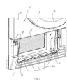
- FIG 2 shows a perspective detailed view of a drying air circuit access opening of the laundry dryer illustrated in Figure 1 wherein an outer door has been removed and an inner panel is shown in its opened position;
- FIG 3 shows the laundry dryer view of Figure 2 wherein the inner panel has been removed
- Figure 4 shows a back side of the inner panel of Figure 2 ;
- Figure 5 shows an enlarged view of detail "A" in Figure 4 ;
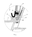
- Figure 6 shows a cross sectional side view of a coupling between the inner panel depicted in Figure 4 and the drying air opening access;
- a laundry dryer comprises a casing 1 formed by a first couple of upright side walls 2A, 2B arranged on a front and rear side of the laundry machine and by a second couple of upright side wall 2C, 2D arranged on lateral sides of such machine.
- An upper wall portion 3 and a bottom wall portion 4 close the ends of the box-like structure formed by the upright side walls 2A, 2B, 2C, 2D, joined together.
- a laundry container comprising a drum (not shown) rotatably mounted in a tub is provided within the casing 1. Further operational devices, such as a drying air circuit, heat exchanging devices, fluid conduits, fluid pumping devices and so on, for carrying out a drying treatment on laundry are provided within the casing 1.
- An extractable moisture tank in the form of a drawer 6 is slidably arranged on the top of the casing 1, for being periodically emptied by a user in case the laundry dryer cannot be connected to a waste water net through a pipe.
- a user control interface 7 is arranged on the top of the casing 1 near the drawer 6 for input of laundry drying programs and displaying machine working conditions.
- a basement 8 is provided as supporting structure for operational devices of drying machine.
- a door arrangement 9 for closing an opening 10 that gives access to a portion of a drying air circuit 11 (see Figure 2 ) where air for drying laundry circulates through the drum and a heat exchanging unit 16, such as an air/air heat exchanger or an evaporator of heap pump circuit, adapted to cools and dehumidifies the drying air.
- Door arrangement 9 comprises an outer door 12 pivotally coupled to casing 1 by a hinge 13 and a inner panel 14 that is removably and pivotally mounted on basement 8.
- the outer door 12 covers panel 14 when both of them are in a closed position.
- Hinge 13 of the outer door 12 is arranged on a side of the opening 10 such that door 12 can be opened, for example, with a clockwise rotation about hinge 13 whose axis extends perpendicularly to a surface where the laundry dryer rests.
- Panel 14 comprises a locking device 15, which serves for temporary fixing panel 14 to casing 1.
- locking device 15 is shown in a form of a plate rotatably driven by a wing nut, however it may be embodied in several known forms all allowing a prompt and quick locking/unlocking operation.
- FIG. 2 the outer door 12 has been removed from hinge 13, and panel 14 has been opened by unlocking the locking device 15.
- a portion of a drying air circuit 11 becomes accessible to a user thereby allowing she/he to perform periodical cleaning of some operational devices like, for example, an extractable air filter (not shown) to be arranged at the portion of the drying circuit 11 between the panel 14 and the heat exchanging unit 16.
- Panel 14 is pivotally coupled to basement 8 and rotates about an axis which is preferably substantially orthogonal to the rotational axis of the outer door 12.
- a gasket 17 is removably associated to panel 14 and extends along the whole peripheral region thereof to tightly close opening 10 thereby avoiding any drying air leakage.
- FIG 3 shows opening 10 without the outer door 12 and the panel 14.
- basement 8 comprises a hinge supporting portion 18 which is advantageously integrally formed on said basement 8 as a single unitary piece.
- Hinge supporting portion 18 is arranged to removably receive therein a hinge-like edge region 19 of panel 14.
- the hinge supporting portion 18 comprises a plurality of first wings 20A arranged in a line and preferably in a manner spaced apart from one another. Similarly to the first wings 20A, a further plurality of second wings 20B are arranged in a line parallel and spaced apart from that formed by first wings 20A . Wings 20B are also preferably spaced apart from one another so as to form a staggered pattern with wings 20A. In other words wings 20B, substantially face gaps between two adjacent wings 20A or between a wing 20A and the opening 10 egde.
- wings 20A, 20B are bent one towards the other so as to form a substantially cylindrical space 21 therebetween for accommodating the hinge-like edge region 19 of panel 14.
- said wings 20A, 20B are preferably elastically deformable so as to flex outwardly thereby enlarging the cylindrical space 21 and consequently loosening the hinge supporting region 18. Insertion and/or removal of the hinge-like edge region 19 from the hinge supporting portion 18 may be performed respectively by pushing or pulling panel 14 into or out the cylindrical space 21.
- one or more locating projections 22 are integrally formed with and projects from basement 8. Such locating projections 22 can be received within corresponding slots 23 provided in proximity of the hinge-like edge region 19, by rotating panel 14 from a substantially closed position in which it obstructs opening 10 to an opened position. Further slots 24, arranged in a line and spaced apart from one another, are formed in proximity of the hinge-like edge region 19 for receiving wings 20B therein. Slots 23, 24 are adapted to receive wings 20B so as to enable the panel to rotate into fully open position wherein the panel lies in a substantially horizontal condition as shown in figure 2 .
- the hinge-like edge region 19 extends along a side of the panel 14.
- the side of the panel 14 having the hinge-like edge region 19 lies on a horizontal axis when the panel 14 is pivotally coupled to the basement 8.
- Figure 5 shows an enlarged view of the hinge-like edge region 19 which has a transverse cross sectional rounded shape so as to improve its insertion and removal from wings 20A, 20B.
- a laundry dryer according to the invention provides an improved structure for hingedly arranging a covering panel for closing an aperture that allows access to a drying air circuit.
- Advantageously said structure is partly integrated in the basement body so as to be formed as a single piece therewith.
- a covering panel as described above may remain attached to the laundry dryer casing or, if desired, it may be easily removed from the casing by pulling a hinge region thereof out of supporting wings provided on the machine basement. In this manner, the user can easily remove and clean the covering panel that normally tens to collect fluff and the like.
- Such arrangement for a drying air circuit access door may be applied not only to all laundry dryer types, such as a heat pump type laundry dryer, a air/air condenser type laundry dryer a washing-drying machine and the like but also to any other type of water bearing appliance in which it is needed to access internal operational devices.
- the inventive laundry dryer may be produced with a less assembling operation and at a cheap cost.
Landscapes
- Engineering & Computer Science (AREA)
- Textile Engineering (AREA)
- Detail Structures Of Washing Machines And Dryers (AREA)
Priority Applications (1)
| Application Number | Priority Date | Filing Date | Title |
|---|---|---|---|
| EP10192896.8A EP2458065B1 (fr) | 2010-11-29 | 2010-11-29 | Sèche-linge |
Applications Claiming Priority (1)
| Application Number | Priority Date | Filing Date | Title |
|---|---|---|---|
| EP10192896.8A EP2458065B1 (fr) | 2010-11-29 | 2010-11-29 | Sèche-linge |
Publications (2)
| Publication Number | Publication Date |
|---|---|
| EP2458065A1 true EP2458065A1 (fr) | 2012-05-30 |
| EP2458065B1 EP2458065B1 (fr) | 2014-07-16 |
Family
ID=44064931
Family Applications (1)
| Application Number | Title | Priority Date | Filing Date |
|---|---|---|---|
| EP10192896.8A Active EP2458065B1 (fr) | 2010-11-29 | 2010-11-29 | Sèche-linge |
Country Status (1)
| Country | Link |
|---|---|
| EP (1) | EP2458065B1 (fr) |
Cited By (5)
| Publication number | Priority date | Publication date | Assignee | Title |
|---|---|---|---|---|
| EP2801653A2 (fr) | 2013-05-06 | 2014-11-12 | Miele & Cie. KG | Sèche-linge doté d'une trappe d'inspection |
| DE102013215071A1 (de) * | 2013-08-01 | 2015-02-05 | BSH Bosch und Siemens Hausgeräte GmbH | Wäschebehandlungsgerät mit einer Wartungsöffnung, die durch einen Wartungsverschluss verschließbar ist |
| EP2905371A1 (fr) * | 2014-02-11 | 2015-08-12 | Samsung Electronics Co., Ltd | Machine à laver |
| EP3216911A1 (fr) * | 2016-03-08 | 2017-09-13 | BSH Hausgeräte GmbH | Appareil d'entretien de linge comprenant un élément d'étanchéité |
| CN110344218A (zh) * | 2019-06-25 | 2019-10-18 | 苏州佳瓦智能科技有限公司 | 一种方便维修的可干洗可水洗的一体式洗衣机外壳 |
Families Citing this family (1)
| Publication number | Priority date | Publication date | Assignee | Title |
|---|---|---|---|---|
| CN106149313B (zh) * | 2016-07-29 | 2019-02-22 | 无锡小天鹅股份有限公司 | 滚筒洗衣机的过滤器组件和具有其的滚筒洗衣机 |
Citations (8)
| Publication number | Priority date | Publication date | Assignee | Title |
|---|---|---|---|---|
| CA1227147A (fr) * | 1984-11-14 | 1987-09-22 | Gerhard S.E. Schmidt | Boite a poudre de maquillage |
| GB2239674A (en) * | 1989-12-12 | 1991-07-10 | Invicta Plastics Ltd | Hinge assembly |
| DE4140266C1 (fr) * | 1991-12-06 | 1993-03-18 | Draegerwerk Ag, 2400 Luebeck, De | |
| WO1994006601A1 (fr) * | 1992-09-12 | 1994-03-31 | Denis Victor Paul Trice | Plan de travail repliable |
| AU672015B2 (en) * | 1992-08-25 | 1996-09-19 | Viscount Plastics Pty Ltd | A hinge |
| WO2003095320A1 (fr) * | 2002-05-09 | 2003-11-20 | Rubbermaid Incorporated | Charniere de recipient multifonctionnelle |
| EP1524359A1 (fr) * | 2003-10-16 | 2005-04-20 | Electrolux Home Products Corporation N.V. | Sèche-linge domestique à condensation avec accouplement de sécurité du réservoir pour collecter l'eau condensée |
| EP2107155A2 (fr) * | 2008-04-01 | 2009-10-07 | Miele & Cie. KG | Machine de traitement du linge, notamment sèche-linge |
-
2010
- 2010-11-29 EP EP10192896.8A patent/EP2458065B1/fr active Active
Patent Citations (8)
| Publication number | Priority date | Publication date | Assignee | Title |
|---|---|---|---|---|
| CA1227147A (fr) * | 1984-11-14 | 1987-09-22 | Gerhard S.E. Schmidt | Boite a poudre de maquillage |
| GB2239674A (en) * | 1989-12-12 | 1991-07-10 | Invicta Plastics Ltd | Hinge assembly |
| DE4140266C1 (fr) * | 1991-12-06 | 1993-03-18 | Draegerwerk Ag, 2400 Luebeck, De | |
| AU672015B2 (en) * | 1992-08-25 | 1996-09-19 | Viscount Plastics Pty Ltd | A hinge |
| WO1994006601A1 (fr) * | 1992-09-12 | 1994-03-31 | Denis Victor Paul Trice | Plan de travail repliable |
| WO2003095320A1 (fr) * | 2002-05-09 | 2003-11-20 | Rubbermaid Incorporated | Charniere de recipient multifonctionnelle |
| EP1524359A1 (fr) * | 2003-10-16 | 2005-04-20 | Electrolux Home Products Corporation N.V. | Sèche-linge domestique à condensation avec accouplement de sécurité du réservoir pour collecter l'eau condensée |
| EP2107155A2 (fr) * | 2008-04-01 | 2009-10-07 | Miele & Cie. KG | Machine de traitement du linge, notamment sèche-linge |
Cited By (8)
| Publication number | Priority date | Publication date | Assignee | Title |
|---|---|---|---|---|
| EP2801653A2 (fr) | 2013-05-06 | 2014-11-12 | Miele & Cie. KG | Sèche-linge doté d'une trappe d'inspection |
| DE102013104603A1 (de) * | 2013-05-06 | 2014-11-20 | Miele & Cie. Kg | Wäschetrockner mit einer Revisionsklappe |
| EP2801653A3 (fr) * | 2013-05-06 | 2015-01-07 | Miele & Cie. KG | Sèche-linge doté d'une trappe d'inspection |
| DE102013104603B4 (de) * | 2013-05-06 | 2016-04-07 | Miele & Cie. Kg | Wäschetrockner mit einer Revisionsklappe |
| DE102013215071A1 (de) * | 2013-08-01 | 2015-02-05 | BSH Bosch und Siemens Hausgeräte GmbH | Wäschebehandlungsgerät mit einer Wartungsöffnung, die durch einen Wartungsverschluss verschließbar ist |
| EP2905371A1 (fr) * | 2014-02-11 | 2015-08-12 | Samsung Electronics Co., Ltd | Machine à laver |
| EP3216911A1 (fr) * | 2016-03-08 | 2017-09-13 | BSH Hausgeräte GmbH | Appareil d'entretien de linge comprenant un élément d'étanchéité |
| CN110344218A (zh) * | 2019-06-25 | 2019-10-18 | 苏州佳瓦智能科技有限公司 | 一种方便维修的可干洗可水洗的一体式洗衣机外壳 |
Also Published As
| Publication number | Publication date |
|---|---|
| EP2458065B1 (fr) | 2014-07-16 |
Similar Documents
| Publication | Publication Date | Title |
|---|---|---|
| EP2458065B1 (fr) | Sèche-linge | |
| JP6126165B2 (ja) | 衣類処理装置 | |
| JP6110432B2 (ja) | 衣類処理装置 | |
| RU2607549C2 (ru) | Устройство для обработки белья | |
| EP2453053B1 (fr) | Machine à laver | |
| CA2893187C (fr) | Appareil de traitement de lessive equipe d'un guide de corps servant a guider le mouvement rotatif d'un corps le long duquel un canal d'approvisionnement d'eau est fourni | |
| KR101590012B1 (ko) | 의류처리장치 | |
| CA2750476C (fr) | Appareil de blanchisserie a dispositif de verrouillage | |
| EP3237674B1 (fr) | Appareil de séchage du linge équipé d'une pompe de vidange de liquide | |
| CN110230172A (zh) | 洗衣机用过滤装置和安装有该装置的洗衣机 | |
| JP6063332B2 (ja) | 洗濯機用ろ過装置及びこれを取り付けた洗濯機 | |
| RU2423564C2 (ru) | Средство для доступа к сливному фильтру стиральной машины с верхней загрузкой | |
| EP3124683B1 (fr) | Seche-linge | |
| EP2280113A1 (fr) | Machine à laver et ensemble de filtrage pour le circuit de drainage d'une machine à laver | |
| KR101989891B1 (ko) | 의류처리장치 및 의류처리방법 | |
| KR20240085023A (ko) | 의류처리장치 | |
| KR101590011B1 (ko) | 의류처리장치 | |
| EP2280112A1 (fr) | Machine à laver et ensemble de filtrage pour le circuit de drainage d'une machine à laver |
Legal Events
| Date | Code | Title | Description |
|---|---|---|---|
| PUAI | Public reference made under article 153(3) epc to a published international application that has entered the european phase |
Free format text: ORIGINAL CODE: 0009012 |
|
| AK | Designated contracting states |
Kind code of ref document: A1 Designated state(s): AL AT BE BG CH CY CZ DE DK EE ES FI FR GB GR HR HU IE IS IT LI LT LU LV MC MK MT NL NO PL PT RO RS SE SI SK SM TR |
|
| AX | Request for extension of the european patent |
Extension state: BA ME |
|
| 17P | Request for examination filed |
Effective date: 20121130 |
|
| GRAP | Despatch of communication of intention to grant a patent |
Free format text: ORIGINAL CODE: EPIDOSNIGR1 |
|
| INTG | Intention to grant announced |
Effective date: 20140211 |
|
| GRAS | Grant fee paid |
Free format text: ORIGINAL CODE: EPIDOSNIGR3 |
|
| GRAA | (expected) grant |
Free format text: ORIGINAL CODE: 0009210 |
|
| AK | Designated contracting states |
Kind code of ref document: B1 Designated state(s): AL AT BE BG CH CY CZ DE DK EE ES FI FR GB GR HR HU IE IS IT LI LT LU LV MC MK MT NL NO PL PT RO RS SE SI SK SM TR |
|
| REG | Reference to a national code |
Ref country code: GB Ref legal event code: FG4D |
|
| REG | Reference to a national code |
Ref country code: CH Ref legal event code: EP |
|
| REG | Reference to a national code |
Ref country code: IE Ref legal event code: FG4D |
|
| REG | Reference to a national code |
Ref country code: AT Ref legal event code: REF Ref document number: 677744 Country of ref document: AT Kind code of ref document: T Effective date: 20140815 |
|
| REG | Reference to a national code |
Ref country code: DE Ref legal event code: R096 Ref document number: 602010017454 Country of ref document: DE Effective date: 20140828 |
|
| REG | Reference to a national code |
Ref country code: NL Ref legal event code: VDEP Effective date: 20140716 |
|
| REG | Reference to a national code |
Ref country code: AT Ref legal event code: MK05 Ref document number: 677744 Country of ref document: AT Kind code of ref document: T Effective date: 20140716 |
|
| REG | Reference to a national code |
Ref country code: LT Ref legal event code: MG4D |
|
| PG25 | Lapsed in a contracting state [announced via postgrant information from national office to epo] |
Ref country code: BG Free format text: LAPSE BECAUSE OF FAILURE TO SUBMIT A TRANSLATION OF THE DESCRIPTION OR TO PAY THE FEE WITHIN THE PRESCRIBED TIME-LIMIT Effective date: 20141016 Ref country code: LT Free format text: LAPSE BECAUSE OF FAILURE TO SUBMIT A TRANSLATION OF THE DESCRIPTION OR TO PAY THE FEE WITHIN THE PRESCRIBED TIME-LIMIT Effective date: 20140716 Ref country code: FI Free format text: LAPSE BECAUSE OF FAILURE TO SUBMIT A TRANSLATION OF THE DESCRIPTION OR TO PAY THE FEE WITHIN THE PRESCRIBED TIME-LIMIT Effective date: 20140716 Ref country code: NO Free format text: LAPSE BECAUSE OF FAILURE TO SUBMIT A TRANSLATION OF THE DESCRIPTION OR TO PAY THE FEE WITHIN THE PRESCRIBED TIME-LIMIT Effective date: 20141016 Ref country code: GR Free format text: LAPSE BECAUSE OF FAILURE TO SUBMIT A TRANSLATION OF THE DESCRIPTION OR TO PAY THE FEE WITHIN THE PRESCRIBED TIME-LIMIT Effective date: 20141017 Ref country code: SE Free format text: LAPSE BECAUSE OF FAILURE TO SUBMIT A TRANSLATION OF THE DESCRIPTION OR TO PAY THE FEE WITHIN THE PRESCRIBED TIME-LIMIT Effective date: 20140716 Ref country code: ES Free format text: LAPSE BECAUSE OF FAILURE TO SUBMIT A TRANSLATION OF THE DESCRIPTION OR TO PAY THE FEE WITHIN THE PRESCRIBED TIME-LIMIT Effective date: 20140716 Ref country code: PT Free format text: LAPSE BECAUSE OF FAILURE TO SUBMIT A TRANSLATION OF THE DESCRIPTION OR TO PAY THE FEE WITHIN THE PRESCRIBED TIME-LIMIT Effective date: 20141117 |
|
| PG25 | Lapsed in a contracting state [announced via postgrant information from national office to epo] |
Ref country code: NL Free format text: LAPSE BECAUSE OF FAILURE TO SUBMIT A TRANSLATION OF THE DESCRIPTION OR TO PAY THE FEE WITHIN THE PRESCRIBED TIME-LIMIT Effective date: 20140716 Ref country code: AT Free format text: LAPSE BECAUSE OF FAILURE TO SUBMIT A TRANSLATION OF THE DESCRIPTION OR TO PAY THE FEE WITHIN THE PRESCRIBED TIME-LIMIT Effective date: 20140716 Ref country code: PL Free format text: LAPSE BECAUSE OF FAILURE TO SUBMIT A TRANSLATION OF THE DESCRIPTION OR TO PAY THE FEE WITHIN THE PRESCRIBED TIME-LIMIT Effective date: 20140716 Ref country code: IS Free format text: LAPSE BECAUSE OF FAILURE TO SUBMIT A TRANSLATION OF THE DESCRIPTION OR TO PAY THE FEE WITHIN THE PRESCRIBED TIME-LIMIT Effective date: 20141116 Ref country code: CY Free format text: LAPSE BECAUSE OF FAILURE TO SUBMIT A TRANSLATION OF THE DESCRIPTION OR TO PAY THE FEE WITHIN THE PRESCRIBED TIME-LIMIT Effective date: 20140716 Ref country code: RS Free format text: LAPSE BECAUSE OF FAILURE TO SUBMIT A TRANSLATION OF THE DESCRIPTION OR TO PAY THE FEE WITHIN THE PRESCRIBED TIME-LIMIT Effective date: 20140716 Ref country code: LV Free format text: LAPSE BECAUSE OF FAILURE TO SUBMIT A TRANSLATION OF THE DESCRIPTION OR TO PAY THE FEE WITHIN THE PRESCRIBED TIME-LIMIT Effective date: 20140716 |
|
| REG | Reference to a national code |
Ref country code: DE Ref legal event code: R097 Ref document number: 602010017454 Country of ref document: DE |
|
| PG25 | Lapsed in a contracting state [announced via postgrant information from national office to epo] |
Ref country code: SK Free format text: LAPSE BECAUSE OF FAILURE TO SUBMIT A TRANSLATION OF THE DESCRIPTION OR TO PAY THE FEE WITHIN THE PRESCRIBED TIME-LIMIT Effective date: 20140716 Ref country code: CZ Free format text: LAPSE BECAUSE OF FAILURE TO SUBMIT A TRANSLATION OF THE DESCRIPTION OR TO PAY THE FEE WITHIN THE PRESCRIBED TIME-LIMIT Effective date: 20140716 Ref country code: DK Free format text: LAPSE BECAUSE OF FAILURE TO SUBMIT A TRANSLATION OF THE DESCRIPTION OR TO PAY THE FEE WITHIN THE PRESCRIBED TIME-LIMIT Effective date: 20140716 Ref country code: RO Free format text: LAPSE BECAUSE OF FAILURE TO SUBMIT A TRANSLATION OF THE DESCRIPTION OR TO PAY THE FEE WITHIN THE PRESCRIBED TIME-LIMIT Effective date: 20140716 Ref country code: EE Free format text: LAPSE BECAUSE OF FAILURE TO SUBMIT A TRANSLATION OF THE DESCRIPTION OR TO PAY THE FEE WITHIN THE PRESCRIBED TIME-LIMIT Effective date: 20140716 |
|
| PLBE | No opposition filed within time limit |
Free format text: ORIGINAL CODE: 0009261 |
|
| STAA | Information on the status of an ep patent application or granted ep patent |
Free format text: STATUS: NO OPPOSITION FILED WITHIN TIME LIMIT |
|
| 26N | No opposition filed |
Effective date: 20150417 |
|
| PG25 | Lapsed in a contracting state [announced via postgrant information from national office to epo] |
Ref country code: BE Free format text: LAPSE BECAUSE OF NON-PAYMENT OF DUE FEES Effective date: 20141130 Ref country code: LU Free format text: LAPSE BECAUSE OF FAILURE TO SUBMIT A TRANSLATION OF THE DESCRIPTION OR TO PAY THE FEE WITHIN THE PRESCRIBED TIME-LIMIT Effective date: 20141129 Ref country code: MC Free format text: LAPSE BECAUSE OF FAILURE TO SUBMIT A TRANSLATION OF THE DESCRIPTION OR TO PAY THE FEE WITHIN THE PRESCRIBED TIME-LIMIT Effective date: 20140716 |
|
| REG | Reference to a national code |
Ref country code: CH Ref legal event code: PL |
|
| PG25 | Lapsed in a contracting state [announced via postgrant information from national office to epo] |
Ref country code: CH Free format text: LAPSE BECAUSE OF NON-PAYMENT OF DUE FEES Effective date: 20141130 Ref country code: LI Free format text: LAPSE BECAUSE OF NON-PAYMENT OF DUE FEES Effective date: 20141130 |
|
| REG | Reference to a national code |
Ref country code: IE Ref legal event code: MM4A |
|
| PG25 | Lapsed in a contracting state [announced via postgrant information from national office to epo] |
Ref country code: IE Free format text: LAPSE BECAUSE OF NON-PAYMENT OF DUE FEES Effective date: 20141129 |
|
| REG | Reference to a national code |
Ref country code: FR Ref legal event code: PLFP Year of fee payment: 6 |
|
| PG25 | Lapsed in a contracting state [announced via postgrant information from national office to epo] |
Ref country code: SI Free format text: LAPSE BECAUSE OF FAILURE TO SUBMIT A TRANSLATION OF THE DESCRIPTION OR TO PAY THE FEE WITHIN THE PRESCRIBED TIME-LIMIT Effective date: 20140716 |
|
| PG25 | Lapsed in a contracting state [announced via postgrant information from national office to epo] |
Ref country code: SM Free format text: LAPSE BECAUSE OF FAILURE TO SUBMIT A TRANSLATION OF THE DESCRIPTION OR TO PAY THE FEE WITHIN THE PRESCRIBED TIME-LIMIT Effective date: 20140716 |
|
| PG25 | Lapsed in a contracting state [announced via postgrant information from national office to epo] |
Ref country code: HU Free format text: LAPSE BECAUSE OF FAILURE TO SUBMIT A TRANSLATION OF THE DESCRIPTION OR TO PAY THE FEE WITHIN THE PRESCRIBED TIME-LIMIT; INVALID AB INITIO Effective date: 20101129 Ref country code: MT Free format text: LAPSE BECAUSE OF FAILURE TO SUBMIT A TRANSLATION OF THE DESCRIPTION OR TO PAY THE FEE WITHIN THE PRESCRIBED TIME-LIMIT Effective date: 20140716 Ref country code: BE Free format text: LAPSE BECAUSE OF FAILURE TO SUBMIT A TRANSLATION OF THE DESCRIPTION OR TO PAY THE FEE WITHIN THE PRESCRIBED TIME-LIMIT Effective date: 20140716 Ref country code: HR Free format text: LAPSE BECAUSE OF FAILURE TO SUBMIT A TRANSLATION OF THE DESCRIPTION OR TO PAY THE FEE WITHIN THE PRESCRIBED TIME-LIMIT Effective date: 20140716 Ref country code: TR Free format text: LAPSE BECAUSE OF FAILURE TO SUBMIT A TRANSLATION OF THE DESCRIPTION OR TO PAY THE FEE WITHIN THE PRESCRIBED TIME-LIMIT Effective date: 20140716 |
|
| REG | Reference to a national code |
Ref country code: FR Ref legal event code: PLFP Year of fee payment: 7 |
|
| PGFP | Annual fee paid to national office [announced via postgrant information from national office to epo] |
Ref country code: FR Payment date: 20161118 Year of fee payment: 7 Ref country code: GB Payment date: 20161122 Year of fee payment: 7 |
|
| PG25 | Lapsed in a contracting state [announced via postgrant information from national office to epo] |
Ref country code: MK Free format text: LAPSE BECAUSE OF FAILURE TO SUBMIT A TRANSLATION OF THE DESCRIPTION OR TO PAY THE FEE WITHIN THE PRESCRIBED TIME-LIMIT Effective date: 20140716 |
|
| GBPC | Gb: european patent ceased through non-payment of renewal fee |
Effective date: 20171129 |
|
| REG | Reference to a national code |
Ref country code: FR Ref legal event code: ST Effective date: 20180731 |
|
| PG25 | Lapsed in a contracting state [announced via postgrant information from national office to epo] |
Ref country code: AL Free format text: LAPSE BECAUSE OF FAILURE TO SUBMIT A TRANSLATION OF THE DESCRIPTION OR TO PAY THE FEE WITHIN THE PRESCRIBED TIME-LIMIT Effective date: 20140716 Ref country code: FR Free format text: LAPSE BECAUSE OF NON-PAYMENT OF DUE FEES Effective date: 20171130 |
|
| PG25 | Lapsed in a contracting state [announced via postgrant information from national office to epo] |
Ref country code: GB Free format text: LAPSE BECAUSE OF NON-PAYMENT OF DUE FEES Effective date: 20171129 |
|
| P01 | Opt-out of the competence of the unified patent court (upc) registered |
Effective date: 20230625 |
|
| PGFP | Annual fee paid to national office [announced via postgrant information from national office to epo] |
Ref country code: DE Payment date: 20251126 Year of fee payment: 16 |
|
| PGFP | Annual fee paid to national office [announced via postgrant information from national office to epo] |
Ref country code: IT Payment date: 20251121 Year of fee payment: 16 |