EP2458111A2 - Elément de coffrage de plafond et système de coffrage de plafond - Google Patents
Elément de coffrage de plafond et système de coffrage de plafond Download PDFInfo
- Publication number
- EP2458111A2 EP2458111A2 EP11192775A EP11192775A EP2458111A2 EP 2458111 A2 EP2458111 A2 EP 2458111A2 EP 11192775 A EP11192775 A EP 11192775A EP 11192775 A EP11192775 A EP 11192775A EP 2458111 A2 EP2458111 A2 EP 2458111A2
- Authority
- EP
- European Patent Office
- Prior art keywords
- support
- formwork
- slab
- slab formwork
- ceiling
- Prior art date
- Legal status (The legal status is an assumption and is not a legal conclusion. Google has not performed a legal analysis and makes no representation as to the accuracy of the status listed.)
- Withdrawn
Links
- 229910052751 metal Inorganic materials 0.000 claims abstract description 7
- 239000002184 metal Substances 0.000 claims abstract description 7
- 229920002430 Fibre-reinforced plastic Polymers 0.000 claims abstract description 4
- 239000011151 fibre-reinforced plastic Substances 0.000 claims abstract description 4
- 238000009415 formwork Methods 0.000 claims description 205
- 229910000831 Steel Inorganic materials 0.000 claims description 8
- 239000010959 steel Substances 0.000 claims description 8
- 239000000969 carrier Substances 0.000 claims description 7
- 238000009416 shuttering Methods 0.000 description 12
- 230000008901 benefit Effects 0.000 description 9
- 230000002349 favourable effect Effects 0.000 description 4
- 230000007704 transition Effects 0.000 description 4
- 239000002023 wood Substances 0.000 description 4
- 230000008859 change Effects 0.000 description 3
- 238000010276 construction Methods 0.000 description 2
- 238000013461 design Methods 0.000 description 2
- 238000006073 displacement reaction Methods 0.000 description 2
- 239000000463 material Substances 0.000 description 2
- 238000000034 method Methods 0.000 description 2
- 230000002093 peripheral effect Effects 0.000 description 2
- 239000004033 plastic Substances 0.000 description 2
- 229920003023 plastic Polymers 0.000 description 2
- 229910052782 aluminium Inorganic materials 0.000 description 1
- XAGFODPZIPBFFR-UHFFFAOYSA-N aluminium Chemical compound [Al] XAGFODPZIPBFFR-UHFFFAOYSA-N 0.000 description 1
- 230000015572 biosynthetic process Effects 0.000 description 1
- 238000011109 contamination Methods 0.000 description 1
- 230000007423 decrease Effects 0.000 description 1
- 238000011161 development Methods 0.000 description 1
- 230000018109 developmental process Effects 0.000 description 1
- 238000013383 initial experiment Methods 0.000 description 1
- 230000003993 interaction Effects 0.000 description 1
- 238000010409 ironing Methods 0.000 description 1
- 229920000642 polymer Polymers 0.000 description 1
- 230000036316 preload Effects 0.000 description 1
- 230000008569 process Effects 0.000 description 1
- 230000003014 reinforcing effect Effects 0.000 description 1
- 230000000284 resting effect Effects 0.000 description 1
- 239000002689 soil Substances 0.000 description 1
- 239000000725 suspension Substances 0.000 description 1
- 238000012360 testing method Methods 0.000 description 1
- 238000012549 training Methods 0.000 description 1
- 230000001960 triggered effect Effects 0.000 description 1
- 230000003313 weakening effect Effects 0.000 description 1
Images

Classifications
-
- E—FIXED CONSTRUCTIONS
- E04—BUILDING
- E04G—SCAFFOLDING; FORMS; SHUTTERING; BUILDING IMPLEMENTS OR AIDS, OR THEIR USE; HANDLING BUILDING MATERIALS ON THE SITE; REPAIRING, BREAKING-UP OR OTHER WORK ON EXISTING BUILDINGS
- E04G11/00—Forms, shutterings, or falsework for making walls, floors, ceilings, or roofs
- E04G11/36—Forms, shutterings, or falsework for making walls, floors, ceilings, or roofs for floors, ceilings, or roofs of plane or curved surfaces end formpanels for floor shutterings
- E04G11/48—Supporting structures for shutterings or frames for floors or roofs
- E04G11/486—Dropheads supporting the concrete after removal of the shuttering; Connecting means on beams specially adapted for dropheads
-
- E—FIXED CONSTRUCTIONS
- E04—BUILDING
- E04G—SCAFFOLDING; FORMS; SHUTTERING; BUILDING IMPLEMENTS OR AIDS, OR THEIR USE; HANDLING BUILDING MATERIALS ON THE SITE; REPAIRING, BREAKING-UP OR OTHER WORK ON EXISTING BUILDINGS
- E04G11/00—Forms, shutterings, or falsework for making walls, floors, ceilings, or roofs
- E04G11/36—Forms, shutterings, or falsework for making walls, floors, ceilings, or roofs for floors, ceilings, or roofs of plane or curved surfaces end formpanels for floor shutterings
- E04G11/48—Supporting structures for shutterings or frames for floors or roofs
- E04G11/50—Girders, beams, or the like as supporting members for forms
Definitions
- the invention relates to a slab formwork element and a slab formwork system.
- the DE 33 16 557 C1 a slab formwork system with a drop head and a drop piece, which can perform a certain tilting movement.
- the GB 337 111 A relates to the preamble of claim 1, and the DE 42 11 136 A1 relates to a drop head of a slab formwork with levers that swing out by their own weight and engage in openings of profiles.
- the DE 101 35 664 B4 relates to a support for slab formwork with a drop head, which is divided into two parts, wherein the two parts are mounted differently lowered on the support, and a part is rotatable about the support.
- the invention has for its object to provide a slab formwork element and provided therewith a ceiling formwork system available, in which the slab formwork element can be arranged very safe and / or necessary in the context of switching on and Ausschalens work can be performed safely and efficiently.
- this problem is the one by the ceiling formwork element described in claim 1. Accordingly, this has at least one support with at least one undercut, which is suitable to cooperate with an undercut on a support head, in particular a drop head.
- At least one support undercut with an undercut on at least one slab formwork element cooperate such that the slab formwork element is on the one hand secured against unwanted lifting and on the other hand when stripping of the undercut of the support can be disengaged, and finally can be removed past the pivoted bearing.
- At least one support that this is sleeve-shaped.
- Such a shape forms a substantially vertically extending cavity into which a substantially vertical projection or pin of a counter-support, for example on a support, can be inserted.
- the cavity described is limited to at least three, preferably four sides in the horizontal direction and / or provided with a rounded contour, so that a particularly good interaction with round pins, such as a column head, is possible.
- the ceiling formwork element described herein further comprises at least one support described in more detail below or is such a support.
- the features described below with reference to a carrier can also be provided in another way on the formwork element according to the invention, in particular -paneel. It is preferred that this is provided at least at one end with at least two directed in the same (usually vertical) direction supports, which are arranged at different vertical heights that the carrier on at least two different horizontal levels on other elements of a slab formwork system can be placed ,
- the formwork support is arranged substantially horizontally in use, but it is also conceivable that the use position of the formwork support is vertical, and thus that different positions are possible in the lateral direction.
- the formwork support described herein is not necessarily always provided as a slab formwork support, but it can be used as any formwork support. In any case, directed in the same direction, at least two supports ensure that the formwork support is particularly versatile.
- the supports directed in the same direction have the advantage that this nailability applies to the use on the two (or more) horizontal levels.
- the supports provided on at least two vertical heights can be used particularly well if a grid of several carriers is to be formed.
- several formwork beams can be arranged at a first, lower level.
- by using the higher support can be further formwork support, for example, transverse to the formwork supports mentioned above hang on this, and are then at the same vertical level, such as formwork beams, which are used immediately using their "lower” support, and thus are “higher”.
- the slab formwork carrier can thereby be used as a "transitional support", for example to areas in which another slab formwork system is used, or as an "edge support", for example to existing walls, in order to produce the "correct" level of formwork.
- At least one support whose training at least partially made of metal, especially steel and / or a plastic, in particular fiber-reinforced, proved to be favorable in initial experiments.
- Particular advantages in terms of manageability, and in particular with regard to the flexible use are given in those preferred embodiments, in which below a first support a second support and can be folded away.
- the length of the carrier does not change when using the various supports, so that favorable properties are achieved.
- the two supports in the closed state of the lower support are substantially aligned with each other.
- the ceiling formwork element described herein further comprises at least one support described in more detail below or is such a support.
- This preferably consists at least partially of metal, in particular steel, but may be any other suitable material, such as. As wood, aluminum or fiber reinforced plastic.
- a particular challenge is to be able to continue to manipulate the carrier or a plurality of such carriers, which may be integrated into a formwork element.
- the carrier should save as much weight as possible while at the same time meeting the requirements imposed on the strength. This is achieved by one or more of the measures described below.
- the carrier may be curved at least slightly in the direction of the concrete to be filled. This essentially means a certain "preload” in the direction of the load, which results in that the load can be absorbed particularly well. This is possible in particular without the risk of deflection against the curvature direction, which would lead to unwanted bulges or bulges at the bottom in the finished concrete pavement.
- the described curvature may be formed as a uniform curvature and may be of the order of a few Millimeters, depending on the length of the carrier, for example, about 4 millimeters.
- the slab formwork support can have openings whose size and / or shape and / or orientation and / or distribution changes over the length of the support such that the support is less weakened in a middle area than in at least one end area.
- a support is usually mounted at its ends, and in its course a uniform line load is applied. This results in a load in middle areas, which is greater than in end areas.
- the carrier is provided with openings which are either increasingly smaller and / or less in the central region.
- the openings over the entire carrier can have a substantially constant shape, for example circular, but become smaller towards the middle.
- the shape and / or orientation of the openings in the direction of the center changed in such a way that a smaller weakening occurs here.
- the versatility of the slab formwork support it has proven to be advantageous to design at least one opening such that at least one bracket can be suspended for supporting another, preferably a wooden formwork support.
- the compatibility with other slab formwork systems which for example have wooden formwork beams, can be guaranteed.
- the described suspension for the particularly flexible embodiment of the edge region of the slab formwork system according to the invention is low. It should be noted that for the hanging of the described strap a regular arrangement, in other words a kind of grid, of possibly equal and / or uniform openings is conceivable.
- such an embodiment optionally in combination with one or more of the features described above or below, as well as the use of at least one opening in a slab formwork carrier for hanging at least one bracket for receiving a further, preferably a timber formwork support as subject of the present application to watch.
- This can be largely U-shaped with a bottom whose "width" (viewed from above) corresponds approximately to the width of a carrier (also viewed from above, measured perpendicular to the longitudinal extent of the carrier). At this bottom, two legs may be attached to different sides, so that they are in use largely vertical to different Extend sides of the formwork support.
- the slab formwork carrier alone develops its advantages, but it can be advantageously integrated into a formwork element, in particular panel, and such an element can have several of the described slab formwork supports, so that the advantages described in a special way for a Use shuttering element.
- a formwork element is furthermore preferred in which beams running transversely between edge supports are spaced less in a middle region of the panel than in end areas.
- an embodiment of a formwork element has proved to be particularly favorable, in which any edge support are not curved, and this measure is used only for at least one particularly stressing cross member between the edge beams.
- the invention further provides a slab formwork system with at least one slab formwork element according to the invention and a drop head which has at least one lowerable support for at least one slab form element which can be swiveled out of the vertical projection of the slab formwork element so that the slab formwork element can be lowered past the at least one pivotable support ,
- the support or fall piece of the drop head according to the invention is pivotable such that a slab formwork element such.
- B. a Deckenschalungspaneel or a slab formwork carrier by a movement next to the support and along this can be lowered.
- the above-mentioned "vertical projection” is understood to mean that space which the ceiling formwork element in the position of use thus largely covers horizontally, in the vertical direction, that is, upwards and downwards.
- the slab formwork element usually in the context of lowering, so the Ausschalens not emerge.
- the slab formwork elements can be removed because the concrete is already cured to a certain extent at this time.
- the supports with the drop heads remain in such a way that the (not lowered) head plates of the supports support the concrete ceiling selectively until sufficient further curing.
- the possibility of removing the slab formwork elements is advantageous insofar as these elements can be brought early to another location, typically one to a floor higher ceiling.
- these elements which are subject to special stress and pollution due to the frequent and changing use, in the system according to the invention are not necessarily equipped with moving parts.
- the drop head according to the invention has a (not lowerable) head plate, as well as a connection possibility to a prop.
- a support member is preferably provided, which holds the lowerable support in a first position at a higher level, and in a second position, in which it has been moved, for example by a hammer blow, at a second, lower level.
- the pivoting out of the described vertical projection is particularly simple if a pivot axis of the support is arranged above the support.
- the support can advantageously be initially pivoted upwards, for example by means of the undercut described below, by engagement with the ceiling formwork element, thereby disengaging from the ceiling formwork element. In the subsequent lowering movement, the support can be swung out of the vertical projection simultaneously.
- At least one support has at least one undercut acting in the vertical direction.
- the undercut essentially provides a projection below and on which a suitable portion of a Ceiling formwork element can be kept, so that this, which is quite possible in strong winds, can not be lifted.
- the undercut can also be used to the fact that when lifting the slab formwork element at the beginning of Ausschalvorganges also the support is slightly raised. In the arrangement of the pivot axis of the support above the described undercut moves away from the edge of the slab formwork element and thus comes out of engagement. As a result, the slab formwork element can subsequently be lowered, while the support is swung out of the vertical projection of the slab formwork element, for example by the pressure which the slab formwork element exerts on lowering it.
- the drop head has at least one second support that can be lowered by a distance that differs from a lowering distance of the first support.
- ceiling formwork panels can be placed at the corners of typically a plurality of first, further lowerable supports.
- the surfaces immediately adjacent to the top plate of the drop head are to be closed by separate formwork elements.
- cover strips or small panels have proven to be low, which can be lowered at stripping by a shortened path. This reduces the risk of damage.
- cover strips or small panels for example made of plastic, which each rest on the top plates of the drop heads.
- the small panels or cover strips may be removed after lowering the drop heads together with any larger formwork panels.
- This offers on the one hand economic advantages, because even the small panels or cover strips are used earlier in other floors. Furthermore, there is no longer the risk of breaking the cover strips or small panels.
- a bracket which can be suspended in at least one opening of a formwork support and suitable for placing at least one further formwork support, preferably a timber formwork support, one or more props and one or more slab formwork elements, in particular carrier or -paneele called ,
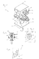
- the in Fig. 1 shown drop head 10 has at its (in the use position shown) lower end substantially a pipe piece 20, with which it can be inserted into the upper end of a prop and fastened thereto.
- a top plate 22 which can also be referred to as a stop plate and on the one hand serves as a tolerance limit and on the other hand limits the movement of the pivotable support described below, which in particular in the last row of panels, if only one of two in common hinged supports is useful.
- the swing plates 24 described in more detail below namely the tendency to pivot completely downwards due to the one-sided load. In this case, there is a risk that the panel from the fully pivoted support disengages and falls.
- the dimensions and positional relationships are preferably selected such that the top plate 22 serves as a stop for the panel 30.
- the weight of the panel 30 causes (see. Fig. 2 ) pivoting the pivot plate 24 (according to the in Fig. 2 shown situation in the clockwise direction) is effected.
- the shuttering panel 30 Due to the Arrangement of the pivot point of the pivot plate 24 above the same moves a pivoting of the pivot plate 24, the shuttering panel 30 in the direction of the drop head 10.
- the shuttering panel 30 strikes the (largely vertically downwardly extending) side surfaces of the top plate 22, so that the pivoting movement of the pivot plate 24 is stopped.
- the formwork panel 30 can thus, as described in more detail below, first be held securely and then removed.
- a so-called second support 18 is provided in the embodiment shown, which serves in this embodiment for laying a cover strip (not shown) whose width substantially the width of the top plate (measured from bottom left to top right according to Fig. 1 ) corresponds.
- the support 18 is lowered in the embodiment shown by a smaller distance than the support 12 described in more detail below.
- two opposite supports 12 are each formed on a common pivot plate 24, so that in each case the corners of two opposite (not shown) slab formwork panels can be placed on these supports.
- tilted drawn swivel plate 24 launched slab formwork panels located in the position of use, the lying on the support 18 cover strip.
- pivot plate 24 is another such pivot plate, so that two slab formwork panels on the left front side of the top plate 22 can be arranged with abutment against each other.
- slab panels and cover strips can be Concrete pavement to be poured.
- the securing member 26 is displaced in a substantially horizontal direction so that it is disengaged from a suitable portion of the drop head and falls down to the base plate 28. As a result, the pivot plates 24 and any lying thereon formwork panels are lowered.
- the Deckenschalungspaneel is designated 30 and is still in the situation shown on the support 12.
- the support 12 has a substantially vertical pin 16 which extends upwardly and an undercut 14 in the form of a (better in Fig. 3 recognizable) projection.
- This undercut acts with an undercut 32 (see. Fig. 3 ) on the slab formwork panel 30 together so that the slab formwork panel 30 is secured in the position of use in an advantageous manner against lifting.
- the projection of the undercut 14 projects substantially into the space formed above the undercut 32.
- the slab formwork panel still from the ground, is supported by a worker with a suitable pole and lowered down so that, as in Fig. 4 shown, sections of the slab form panel on top of the pin 16 so that the pivot plate 24 is pivoted so that the support 12 is sufficiently pivoted out of the vertical projection of the ceiling formwork element 30.
- the support including the pin moves as shown in FIG Fig. 4 to the left, so that the vertical projection of the ceiling formwork element 30 below the same for stripping the slab formwork element and after carrying out the same process on the other side of its removal downwards is free.
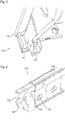
- Fig. 5 is a corner of a formwork element in the form of a Deckenschalungspaneels 110 can be seen.
- the corner 112 thus forms an end in the sense of the preceding description.
- the shuttering panel 110 has beams or profiles, preferably of metal, in particular steel, which in the case shown define a peripheral edge defining a (flat) space in which a formwork panel is inserted, the forms together with numerous other such formwork panels the actual formwork skin.
- the shuttering panel on the described carrier which can form a frame and can be provided as the frame reinforcing cross member.
- two supports 114, 116 are provided in accordance with the principles of the invention.
- both are largely sleeve-shaped, that is closed on at least three sides, and extend differently far from the end of the formwork element formed by the formwork panel (upper position in use position).
- the shuttering panel 110 can be placed at two different levels on suitable other elements of a slab formwork system, for example supports or their heads.
- the higher support 114 is closer to the corner 112 than the lower support 116, which provides handling benefits.
- the supports can cooperate with suitable counter-elements, for example pins, and are thereby secured against displacement in all horizontal directions.
- the formwork panel 110 described above can be described with reference to FIGS Fig. 1 to 4 correspond to panel 30 described.
- the in Fig. 5 shown panel on at least one corner and in at least one support with reference to the Fig. 2 to 4 have described undercut.
- the horizontal fuse is similar to the one in FIG Fig. 6 Shuttering element shown in the form of a formwork support 120 of the case, in which, however, a lower support 130 is switched on and away.
- the lower 130 and the upper supports 132 are in turn provided with a vertically extending cavity, which in this case is bounded on at least three sides and with a rounded Contour is provided.
- a pin or pin of a counter element can enter a pin or pin of a counter element to secure the formwork support against lateral displacement.
- the lower support 130 is pivotable about an axis 134 located below the support 132, so that it is effectively accommodated in the folded-away state in the web 136 of the carrier 120, and does not affect the operational capability of the upper support 132.
- Formwork support shown results in the particular advantage that the two supports 130, 132 are directed in the same direction.
- the formwork support 120 is an always flexible usable ceiling formwork element.
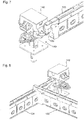
- Fig. 7 It is shown how the formwork support 120 can be placed using the lower support 130 on a support head 140, the support head 10 of Fig. 1 to 4 equivalent.
- the formwork support 120 can be placed on a journal of the same such that the upper edge of the formwork support 120 is level with the top plate 142 of the support head 140.
- formwork panels can be placed on the carrier 120 and the top plate 142.
- the dimensions may be chosen such that the upper edge of the formwork support 120 is located about the thickness of a formwork panel below the top plate 142 so that the created formwork skin is formed both by formwork panels laid on the support 120 and the top panel 142 itself.
- the formwork support 120 can be used as a so-called transition or edge support.
- a transitional carrier it forms the transition from a formwork system, the prefabricated formwork panels and largely strip-shaped small panels between each support heads 142 has, and a region, for example, by using a Holzschalungssystems with wood beams and individually tailored formwork panels is maralt.
- the formwork support 120 shown can be used in an advantageous manner.
- the advantageous use of the formwork support 120 applies in a similar manner at the edges of a formwork system having prefabricated formwork elements. At the edges, for example, towards walls, often individually tailored formwork panels or boards must be used, which can be placed in an advantageous manner on the formwork support 120 described, which then acts as edge support.
- a grid of yoke and cross members are formed.
- the Jochlini 122 on the respect to the top plate 142 "right" level, both the cross members 122 and the Jochlinin 124, the upper supports 132 are used.
- the yoke beams 124 are thus (compared with Fig. 7 ) at a lower level, and the transverse beams 122 placed on the yoke beams 124, as shown, then form the "right" level with respect to the top plate 142.
- This may, as described above, be the same level, so that formwork panels can be placed on the top plate 142 and the cross members 122 in cooperation.
- the cross beams 122 may be located about the thickness of a formwork panel below the top plate 142 so that the on the Crossmember 122 laid formwork panels form a consistent level with the top plates 142, and the formwork is a total of these two elements, in cooperation with each other, is formed.
- Fig. 9 is shown exaggerated in a side view and in terms of the curvature of an advantageous carrier 210 which is integrated in the example shown in a formwork element, of which, however, only edge profiles 212 are shown.
- a formwork panel In the final state is above the profiles 212 and the support 210, a formwork panel, is poured onto the concrete.
- the resulting line load loads the carrier in particular at its central region comparatively extensive, since it is supported at its edges on suitable supports.
- the carrier according to the invention in the in Fig. 9 shown embodiment curved in the direction of the expected load.
- This vault is in Fig. 9
- a few millimeters is used to the carrier according to the invention in the in Fig. 9
- a few millimeters In practice, depending on the length of the carrier, in practice, a few millimeters.
- the carrier shown may in particular be one of possibly a plurality of such cross members, which are at least partially curved in the manner described, while this does not necessarily have to be provided for the edge supports or profiles 212.
- openings 214 are shown which are unevenly distributed over the length of the carrier.
- openings 214 are according to an alternative measure, but with the in Fig. 9 can be combined over the course of the support 220 in terms of their size changed.
- the openings become smaller towards the center and are completely omitted in the illustrated embodiment in the central area, so that this particularly loaded area is significantly less weakened than the end areas.
- the strength can be ensured over the entire course of the carrier, weight being saved especially in the less loaded end regions.
- FIG. 11 shows third embodiment of a carrier 230, which is additionally designed in the end regions A (according to the position of use) less "high" than in a central region. Bearing 232 can be seen at the ends.
- Over the course of the carrier 230 is further provided with openings whose shape, orientation and distribution varies over the length of the carrier.
- openings are provided in the end regions in the form of a respective comparatively flat triangle whose corners are rounded with different radii.
- two sides of the triangle are substantially parallel to edges of the beam, namely to the top edge and the bottom edge inclined in this area. The radius of curvature is greatest towards the end of the beam and smallest at the top, toward the inside of the beam.
- oval or elliptical and rectangular openings may be provided with rounded portions at their ends and, for example, be aligned substantially parallel to the inclined in this area lower edge of the carrier.
- Elliptical or oval openings and / or openings in any of the shapes described above may be substantially vertically aligned with the center of the carrier as shown, and may be substantially horizontally aligned further toward the center. In the middle of the carrier are also found circular openings. Overall, it could be found for the example shown a special distribution, shape and orientation change of the openings that weight can be saved and at the same time the strength is ensured over the entire course of the wearer.
Landscapes
- Engineering & Computer Science (AREA)
- Architecture (AREA)
- Mechanical Engineering (AREA)
- Civil Engineering (AREA)
- Structural Engineering (AREA)
- Forms Removed On Construction Sites Or Auxiliary Members Thereof (AREA)
Applications Claiming Priority (2)
| Application Number | Priority Date | Filing Date | Title |
|---|---|---|---|
| DE201010001042 DE102010001042B4 (de) | 2010-01-20 | 2010-01-20 | Fallkopf für ein Deckenschalungssystem und Deckenschalungssystem |
| EP11700659.3A EP2443299B1 (fr) | 2010-01-20 | 2011-01-19 | Tête de décintrement pour système de coffrage de dalles et système de coffrage de dalles |
Related Parent Applications (1)
| Application Number | Title | Priority Date | Filing Date |
|---|---|---|---|
| EP11700659.3 Division | 2011-01-19 |
Publications (2)
| Publication Number | Publication Date |
|---|---|
| EP2458111A2 true EP2458111A2 (fr) | 2012-05-30 |
| EP2458111A3 EP2458111A3 (fr) | 2013-07-03 |
Family
ID=43735919
Family Applications (2)
| Application Number | Title | Priority Date | Filing Date |
|---|---|---|---|
| EP11192775.2A Withdrawn EP2458111A3 (fr) | 2010-01-20 | 2011-01-19 | Elément de coffrage de plafond et système de coffrage de plafond |
| EP11700659.3A Active EP2443299B1 (fr) | 2010-01-20 | 2011-01-19 | Tête de décintrement pour système de coffrage de dalles et système de coffrage de dalles |
Family Applications After (1)
| Application Number | Title | Priority Date | Filing Date |
|---|---|---|---|
| EP11700659.3A Active EP2443299B1 (fr) | 2010-01-20 | 2011-01-19 | Tête de décintrement pour système de coffrage de dalles et système de coffrage de dalles |
Country Status (3)
| Country | Link |
|---|---|
| EP (2) | EP2458111A3 (fr) |
| DE (1) | DE102010001042B4 (fr) |
| WO (1) | WO2011089148A1 (fr) |
Cited By (3)
| Publication number | Priority date | Publication date | Assignee | Title |
|---|---|---|---|---|
| ITPR20130047A1 (it) * | 2013-05-31 | 2014-12-01 | Tecnotelai Components S R L | Sistema e metodo per la realizzazione di una sovrastruttura |
| DE102015223773A1 (de) * | 2015-11-30 | 2017-06-01 | Peri Gmbh | Stützenkopf, Deckenstütze und Deckenschalung mit einer solchen Deckenstütze |
| DE102024111113A1 (de) * | 2024-04-19 | 2025-10-23 | Peri Se | Horizontalträger, Vorrichtung und Verfahren zur Verschalung einer Betondecke |
Families Citing this family (9)
| Publication number | Priority date | Publication date | Assignee | Title |
|---|---|---|---|---|
| DE102011082841B4 (de) | 2011-09-16 | 2015-10-08 | Doka Industrie Gmbh | Fallkopf für ein Deckenschalungssystem und Verfahren zum Entfernen von Deckenschalungselementen |
| ITPR20120022A1 (it) * | 2012-04-11 | 2013-10-12 | Tecnotelai Components S R L | Testa di sostegno per la realizzazione di una sovrastruttura |
| DE102012206353A1 (de) | 2012-04-18 | 2013-10-24 | Doka Industrie Gmbh | Hebevorrichtung für Deckenschalungselemente sowie Verfahren |
| US11225802B2 (en) | 2017-10-12 | 2022-01-18 | George CHARITOU | Prop head assembly |
| IT201800003425A1 (it) * | 2018-03-12 | 2019-09-12 | Faresin Formwork S P A | "dispositivo perfezionato di supporto, del tipo a testa cadente, per travi di sostegno di casseforme per solai, attrezzatura comprendente tale dispositivo e trave di sostegno da associare al dispositivo" |
| EP3887617B1 (fr) * | 2018-11-29 | 2025-10-29 | Peri Se | Systeme de coffrage de dalle avec tete de decoffrage escamotable |
| US12497790B2 (en) | 2020-12-17 | 2025-12-16 | Faresin Formwork S.p.A. | Supporting head for providing formwork units for floor slabs, and beam and panel for use with the supporting head |
| US11987999B2 (en) | 2021-07-14 | 2024-05-21 | Brand Shared Services Llc | Support head with quick release for formwork system |
| EP4381151A2 (fr) | 2021-08-03 | 2024-06-12 | Peri Se | Système de poutre de grille pour coffrage de dalle |
Citations (5)
| Publication number | Priority date | Publication date | Assignee | Title |
|---|---|---|---|---|
| GB337111A (en) | 1929-04-01 | 1930-10-30 | Henry William Roos | Improvements in apparatus for constructing concrete floors |
| DE3316557C1 (de) | 1983-03-03 | 1984-10-11 | NOE-Schaltechnik GmbH, 7334 Süssen | Deckenschalungssystem |
| DE4211136A1 (de) | 1992-04-03 | 1993-10-07 | Gerhard Dingler | Vorrichtung zur Deckenschalung |
| DE102004004883A1 (de) | 2003-08-04 | 2005-03-10 | Ischebeck Friedrich Gmbh | Deckenschalungs-Paneel und System-Deckenschalung |
| DE10135664B4 (de) | 2001-07-21 | 2008-06-26 | Hünnebeck GmbH | Stütze für Deckenschalungen od. dgl. |
Family Cites Families (14)
| Publication number | Priority date | Publication date | Assignee | Title |
|---|---|---|---|---|
| US1888738A (en) * | 1930-03-13 | 1932-11-22 | Henry W Roos | Adjustable shore |
| US2386161A (en) * | 1943-05-24 | 1945-10-02 | Bryant & Son Ltd C | Temporary support for use in casting concrete floors and similar purposes |
| DE1818217U (de) * | 1960-06-07 | 1960-09-15 | Wuppermann Gmbh Theodor | Kelch- oder aehnliches profil, insbesondere fuer schalungstraeger. |
| US4470574A (en) * | 1978-12-11 | 1984-09-11 | Jackson George W | Support structure for building forms |
| DE3046284A1 (de) * | 1980-12-09 | 1982-07-08 | Hünnebeck GmbH, 4030 Ratingen | Schalungssystem fuer deckenschalungen |
| DE4009425A1 (de) * | 1990-03-23 | 1991-09-26 | Hollmann Niels | Betonierungs-schaltafel |
| DE4211200C2 (de) * | 1992-04-03 | 2000-01-13 | Gerhard Dingler | Vorrichtung für eine Deckenschalung |
| DE4211299C2 (de) * | 1992-04-04 | 2000-01-20 | Dingler Gerhard | Profil - Hauptträger |
| PT1384837E (pt) * | 2001-04-03 | 2009-07-15 | Ulma C Y E S Coop | Sistema de cofragem para chãos e tectos |
| ES2196951B1 (es) * | 2001-04-18 | 2004-10-16 | Ingenieria De Encofrados Y Servicios, S.L. | Encofrado recuperable. |
| EP1617013A1 (fr) * | 2004-07-13 | 2006-01-18 | CEDEMAT - Aluguer de Materiais de Construçao, Lda | Système de coffrage horizontal |
| ITPN20050085A1 (it) * | 2005-11-28 | 2007-05-29 | Ezio Sedran | Trave in plastica per la realizzazione di armamenti di strutture edili orizzontali. |
| DE102006015348A1 (de) * | 2006-04-03 | 2007-10-04 | Peri Gmbh | Deckenschalungssystem |
| DE102007026499B3 (de) * | 2007-06-05 | 2009-02-05 | Peri Gmbh | Trägerelement für eine Betonschalung mit Vorrichtung zur automatischen Kompensation von Biegeverformungen |
-
2010
- 2010-01-20 DE DE201010001042 patent/DE102010001042B4/de active Active
-
2011
- 2011-01-19 WO PCT/EP2011/050663 patent/WO2011089148A1/fr not_active Ceased
- 2011-01-19 EP EP11192775.2A patent/EP2458111A3/fr not_active Withdrawn
- 2011-01-19 EP EP11700659.3A patent/EP2443299B1/fr active Active
Patent Citations (5)
| Publication number | Priority date | Publication date | Assignee | Title |
|---|---|---|---|---|
| GB337111A (en) | 1929-04-01 | 1930-10-30 | Henry William Roos | Improvements in apparatus for constructing concrete floors |
| DE3316557C1 (de) | 1983-03-03 | 1984-10-11 | NOE-Schaltechnik GmbH, 7334 Süssen | Deckenschalungssystem |
| DE4211136A1 (de) | 1992-04-03 | 1993-10-07 | Gerhard Dingler | Vorrichtung zur Deckenschalung |
| DE10135664B4 (de) | 2001-07-21 | 2008-06-26 | Hünnebeck GmbH | Stütze für Deckenschalungen od. dgl. |
| DE102004004883A1 (de) | 2003-08-04 | 2005-03-10 | Ischebeck Friedrich Gmbh | Deckenschalungs-Paneel und System-Deckenschalung |
Cited By (5)
| Publication number | Priority date | Publication date | Assignee | Title |
|---|---|---|---|---|
| ITPR20130047A1 (it) * | 2013-05-31 | 2014-12-01 | Tecnotelai Components S R L | Sistema e metodo per la realizzazione di una sovrastruttura |
| WO2014191959A1 (fr) * | 2013-05-31 | 2014-12-04 | Tecnotelai Components S.R.L. | Système et procédé de construction d'une superstructure |
| DE102015223773A1 (de) * | 2015-11-30 | 2017-06-01 | Peri Gmbh | Stützenkopf, Deckenstütze und Deckenschalung mit einer solchen Deckenstütze |
| US10787826B2 (en) | 2015-11-30 | 2020-09-29 | Peri Gmbh | Support head, ceiling support, and ceiling formwork having such a ceiling support |
| DE102024111113A1 (de) * | 2024-04-19 | 2025-10-23 | Peri Se | Horizontalträger, Vorrichtung und Verfahren zur Verschalung einer Betondecke |
Also Published As
| Publication number | Publication date |
|---|---|
| DE102010001042A1 (de) | 2011-07-21 |
| WO2011089148A1 (fr) | 2011-07-28 |
| DE102010001042B4 (de) | 2012-03-01 |
| EP2443299A1 (fr) | 2012-04-25 |
| EP2443299B1 (fr) | 2013-11-13 |
| EP2458111A3 (fr) | 2013-07-03 |
Similar Documents
| Publication | Publication Date | Title |
|---|---|---|
| EP2443299B1 (fr) | Tête de décintrement pour système de coffrage de dalles et système de coffrage de dalles | |
| WO2019025513A1 (fr) | Procédé de fabrication d'un élément de plafond et coffrage de plafond | |
| DE102007026020A1 (de) | Selbstklettersystem und Verfahren zum Betonieren eines Unterzugs und/oder Montieren eines Fertigteils mittels eines Selbstklettersystems | |
| EP2798133B1 (fr) | Panneau pour un système de coffrage de plafond et système de coffrage de plafond | |
| EP3702550A1 (fr) | Cadre de coffrage, élément de coffrage, coffrage de plafond et procédé | |
| DE102012214396A1 (de) | Wandschalung mit Verbindungseinrichtung | |
| DE2742883A1 (de) | Schalungsvorrichtung zum herstellen von betonwaenden | |
| EP0092694B1 (fr) | Système de coffrage pour plafonds | |
| DE102007021159B4 (de) | Rostdeckenschalung zur Einbindung einer Säule | |
| EP3456902A1 (fr) | Coffrage perdu pour constructions en béton | |
| DE2217584A1 (de) | Klettergeruest fuer betonschalung | |
| EP2570568B1 (fr) | Tête décintrable pour un système de coffrage de plafond et procédé de retrait d'éléments de coffrage de plafond | |
| DE2126254A1 (de) | Vorrichtung zum Betonieren von Bauelementen | |
| DE2458486C3 (de) | Zerlegbare Schalung und Anlage zur Herstellung eines Betonformsteins für den Wasserbau | |
| EP2526243B1 (fr) | Élément de coffrage comprenant une poutrelle | |
| DE102010001044B4 (de) | Deckenschalungselement | |
| DE102012211388A1 (de) | Betonierungs-Deckenschalung | |
| DE2530639A1 (de) | Schalungsgeruest fuer decken | |
| AT412359B (de) | Schalung | |
| AT513573A2 (de) | Verfahren für die Herstellung von Hochhausdecken nebst Schaltafel | |
| DE880057C (de) | Stahlschalung zur Herstellung glatter geschuetteter Waende | |
| DE10022662C2 (de) | Vorrichtung zum schrittweisen Verfahren einer Schalung an einem Betonbauwerk | |
| DE1434341C (de) | Höhen verstellbares Trägerendstück für Einrüstungen, zerlegbare Hallen od. dgl | |
| DE102021120438A1 (de) | System zur Schalung eines Wandelementes mit einem frei stehenden Gerüstabschnitt | |
| DE2109075C3 (de) | Raumschalung |
Legal Events
| Date | Code | Title | Description |
|---|---|---|---|
| PUAI | Public reference made under article 153(3) epc to a published international application that has entered the european phase |
Free format text: ORIGINAL CODE: 0009012 |
|
| AC | Divisional application: reference to earlier application |
Ref document number: 2443299 Country of ref document: EP Kind code of ref document: P |
|
| AK | Designated contracting states |
Kind code of ref document: A2 Designated state(s): AL AT BE BG CH CY CZ DE DK EE ES FI FR GB GR HR HU IE IS IT LI LT LU LV MC MK MT NL NO PL PT RO RS SE SI SK SM TR |
|
| AX | Request for extension of the european patent |
Extension state: BA ME |
|
| PUAL | Search report despatched |
Free format text: ORIGINAL CODE: 0009013 |
|
| AK | Designated contracting states |
Kind code of ref document: A3 Designated state(s): AL AT BE BG CH CY CZ DE DK EE ES FI FR GB GR HR HU IE IS IT LI LT LU LV MC MK MT NL NO PL PT RO RS SE SI SK SM TR |
|
| AX | Request for extension of the european patent |
Extension state: BA ME |
|
| RIC1 | Information provided on ipc code assigned before grant |
Ipc: E04G 11/48 20060101AFI20130527BHEP Ipc: E04G 11/50 20060101ALI20130527BHEP |
|
| STAA | Information on the status of an ep patent application or granted ep patent |
Free format text: STATUS: THE APPLICATION IS DEEMED TO BE WITHDRAWN |
|
| 18D | Application deemed to be withdrawn |
Effective date: 20140104 |