EP2458199B1 - Windturbine mit kompensiertem motordrehmoment - Google Patents
Windturbine mit kompensiertem motordrehmoment Download PDFInfo
- Publication number
- EP2458199B1 EP2458199B1 EP09846732.7A EP09846732A EP2458199B1 EP 2458199 B1 EP2458199 B1 EP 2458199B1 EP 09846732 A EP09846732 A EP 09846732A EP 2458199 B1 EP2458199 B1 EP 2458199B1
- Authority
- EP
- European Patent Office
- Prior art keywords
- rotor
- generator
- shaft
- pendulum
- torque
- Prior art date
- Legal status (The legal status is an assumption and is not a legal conclusion. Google has not performed a legal analysis and makes no representation as to the accuracy of the status listed.)
- Not-in-force
Links
- 238000013461 design Methods 0.000 claims description 22
- 230000033001 locomotion Effects 0.000 claims description 20
- 230000000694 effects Effects 0.000 claims description 15
- 230000005540 biological transmission Effects 0.000 claims description 14
- RLQJEEJISHYWON-UHFFFAOYSA-N flonicamid Chemical compound FC(F)(F)C1=CC=NC=C1C(=O)NCC#N RLQJEEJISHYWON-UHFFFAOYSA-N 0.000 claims description 8
- 229920001971 elastomer Polymers 0.000 claims description 5
- 239000000806 elastomer Substances 0.000 claims description 5
- 230000002706 hydrostatic effect Effects 0.000 claims description 5
- 230000007246 mechanism Effects 0.000 claims description 5
- 238000005381 potential energy Methods 0.000 claims description 5
- 230000006641 stabilisation Effects 0.000 claims description 5
- 238000011105 stabilization Methods 0.000 claims description 5
- 230000000630 rising effect Effects 0.000 claims description 4
- 230000000087 stabilizing effect Effects 0.000 claims description 4
- 230000000368 destabilizing effect Effects 0.000 claims description 3
- 238000009499 grossing Methods 0.000 claims description 3
- 244000203494 Lens culinaris subsp culinaris Species 0.000 claims description 2
- 235000014647 Lens culinaris subsp culinaris Nutrition 0.000 claims description 2
- 230000003094 perturbing effect Effects 0.000 claims 1
- 238000005086 pumping Methods 0.000 description 6
- 238000010612 desalination reaction Methods 0.000 description 4
- 230000005484 gravity Effects 0.000 description 4
- 238000005452 bending Methods 0.000 description 3
- 230000008859 change Effects 0.000 description 3
- 238000012423 maintenance Methods 0.000 description 3
- 238000010521 absorption reaction Methods 0.000 description 2
- 238000009826 distribution Methods 0.000 description 2
- 230000005611 electricity Effects 0.000 description 2
- 238000005516 engineering process Methods 0.000 description 2
- 239000012530 fluid Substances 0.000 description 2
- 239000000543 intermediate Substances 0.000 description 2
- 230000010355 oscillation Effects 0.000 description 2
- 230000009467 reduction Effects 0.000 description 2
- 238000001223 reverse osmosis Methods 0.000 description 2
- 230000002441 reversible effect Effects 0.000 description 2
- 238000004513 sizing Methods 0.000 description 2
- 230000001360 synchronised effect Effects 0.000 description 2
- 239000006096 absorbing agent Substances 0.000 description 1
- 230000001133 acceleration Effects 0.000 description 1
- 230000006978 adaptation Effects 0.000 description 1
- 230000033228 biological regulation Effects 0.000 description 1
- 230000015572 biosynthetic process Effects 0.000 description 1
- 230000000295 complement effect Effects 0.000 description 1
- 230000003247 decreasing effect Effects 0.000 description 1
- 230000009977 dual effect Effects 0.000 description 1
- 230000008030 elimination Effects 0.000 description 1
- 238000003379 elimination reaction Methods 0.000 description 1
- 238000007667 floating Methods 0.000 description 1
- 230000001976 improved effect Effects 0.000 description 1
- 238000009434 installation Methods 0.000 description 1
- 238000004519 manufacturing process Methods 0.000 description 1
- 230000000116 mitigating effect Effects 0.000 description 1
- 230000004048 modification Effects 0.000 description 1
- 238000012986 modification Methods 0.000 description 1
- 238000009987 spinning Methods 0.000 description 1
- 230000003068 static effect Effects 0.000 description 1
- 230000008093 supporting effect Effects 0.000 description 1
- 230000001960 triggered effect Effects 0.000 description 1
- XLYOFNOQVPJJNP-UHFFFAOYSA-N water Substances O XLYOFNOQVPJJNP-UHFFFAOYSA-N 0.000 description 1
Images



Classifications
-
- F—MECHANICAL ENGINEERING; LIGHTING; HEATING; WEAPONS; BLASTING
- F03—MACHINES OR ENGINES FOR LIQUIDS; WIND, SPRING, OR WEIGHT MOTORS; PRODUCING MECHANICAL POWER OR A REACTIVE PROPULSIVE THRUST, NOT OTHERWISE PROVIDED FOR
- F03D—WIND MOTORS
- F03D1/00—Wind motors with rotation axis substantially parallel to the air flow entering the rotor
- F03D1/06—Rotors
- F03D1/0608—Rotors characterised by their aerodynamic shape
-
- F—MECHANICAL ENGINEERING; LIGHTING; HEATING; WEAPONS; BLASTING
- F03—MACHINES OR ENGINES FOR LIQUIDS; WIND, SPRING, OR WEIGHT MOTORS; PRODUCING MECHANICAL POWER OR A REACTIVE PROPULSIVE THRUST, NOT OTHERWISE PROVIDED FOR
- F03D—WIND MOTORS
- F03D15/00—Transmission of mechanical power
-
- F—MECHANICAL ENGINEERING; LIGHTING; HEATING; WEAPONS; BLASTING
- F03—MACHINES OR ENGINES FOR LIQUIDS; WIND, SPRING, OR WEIGHT MOTORS; PRODUCING MECHANICAL POWER OR A REACTIVE PROPULSIVE THRUST, NOT OTHERWISE PROVIDED FOR
- F03D—WIND MOTORS
- F03D15/00—Transmission of mechanical power
- F03D15/10—Transmission of mechanical power using gearing not limited to rotary motion, e.g. with oscillating or reciprocating members
-
- F—MECHANICAL ENGINEERING; LIGHTING; HEATING; WEAPONS; BLASTING
- F03—MACHINES OR ENGINES FOR LIQUIDS; WIND, SPRING, OR WEIGHT MOTORS; PRODUCING MECHANICAL POWER OR A REACTIVE PROPULSIVE THRUST, NOT OTHERWISE PROVIDED FOR
- F03D—WIND MOTORS
- F03D7/00—Controlling wind motors
- F03D7/02—Controlling wind motors the wind motors having rotation axis substantially parallel to the air flow entering the rotor
-
- F—MECHANICAL ENGINEERING; LIGHTING; HEATING; WEAPONS; BLASTING
- F03—MACHINES OR ENGINES FOR LIQUIDS; WIND, SPRING, OR WEIGHT MOTORS; PRODUCING MECHANICAL POWER OR A REACTIVE PROPULSIVE THRUST, NOT OTHERWISE PROVIDED FOR
- F03D—WIND MOTORS
- F03D80/00—Details, components or accessories not provided for in groups F03D1/00 - F03D17/00
- F03D80/70—Bearing or lubricating arrangements
-
- F—MECHANICAL ENGINEERING; LIGHTING; HEATING; WEAPONS; BLASTING
- F05—INDEXING SCHEMES RELATING TO ENGINES OR PUMPS IN VARIOUS SUBCLASSES OF CLASSES F01-F04
- F05B—INDEXING SCHEME RELATING TO WIND, SPRING, WEIGHT, INERTIA OR LIKE MOTORS, TO MACHINES OR ENGINES FOR LIQUIDS COVERED BY SUBCLASSES F03B, F03D AND F03G
- F05B2260/00—Function
- F05B2260/42—Storage of energy
- F05B2260/421—Storage of energy in the form of rotational kinetic energy, e.g. in flywheels
-
- F—MECHANICAL ENGINEERING; LIGHTING; HEATING; WEAPONS; BLASTING
- F05—INDEXING SCHEMES RELATING TO ENGINES OR PUMPS IN VARIOUS SUBCLASSES OF CLASSES F01-F04
- F05B—INDEXING SCHEME RELATING TO WIND, SPRING, WEIGHT, INERTIA OR LIKE MOTORS, TO MACHINES OR ENGINES FOR LIQUIDS COVERED BY SUBCLASSES F03B, F03D AND F03G
- F05B2270/00—Control
- F05B2270/10—Purpose of the control system
- F05B2270/101—Purpose of the control system to control rotational speed (n)
- F05B2270/1014—Purpose of the control system to control rotational speed (n) to keep rotational speed constant
-
- F—MECHANICAL ENGINEERING; LIGHTING; HEATING; WEAPONS; BLASTING
- F05—INDEXING SCHEMES RELATING TO ENGINES OR PUMPS IN VARIOUS SUBCLASSES OF CLASSES F01-F04
- F05B—INDEXING SCHEME RELATING TO WIND, SPRING, WEIGHT, INERTIA OR LIKE MOTORS, TO MACHINES OR ENGINES FOR LIQUIDS COVERED BY SUBCLASSES F03B, F03D AND F03G
- F05B2270/00—Control
- F05B2270/10—Purpose of the control system
- F05B2270/109—Purpose of the control system to prolong engine life
- F05B2270/1095—Purpose of the control system to prolong engine life by limiting mechanical stresses
-
- F—MECHANICAL ENGINEERING; LIGHTING; HEATING; WEAPONS; BLASTING
- F05—INDEXING SCHEMES RELATING TO ENGINES OR PUMPS IN VARIOUS SUBCLASSES OF CLASSES F01-F04
- F05B—INDEXING SCHEME RELATING TO WIND, SPRING, WEIGHT, INERTIA OR LIKE MOTORS, TO MACHINES OR ENGINES FOR LIQUIDS COVERED BY SUBCLASSES F03B, F03D AND F03G
- F05B2270/00—Control
- F05B2270/40—Type of control system
- F05B2270/402—Type of control system passive or reactive, e.g. using large wind vanes
-
- F—MECHANICAL ENGINEERING; LIGHTING; HEATING; WEAPONS; BLASTING
- F05—INDEXING SCHEMES RELATING TO ENGINES OR PUMPS IN VARIOUS SUBCLASSES OF CLASSES F01-F04
- F05B—INDEXING SCHEME RELATING TO WIND, SPRING, WEIGHT, INERTIA OR LIKE MOTORS, TO MACHINES OR ENGINES FOR LIQUIDS COVERED BY SUBCLASSES F03B, F03D AND F03G
- F05B2270/00—Control
- F05B2270/50—Control logic embodiment by
- F05B2270/508—Control logic embodiment by mechanical means, e.g. levers, gears or cams
-
- Y—GENERAL TAGGING OF NEW TECHNOLOGICAL DEVELOPMENTS; GENERAL TAGGING OF CROSS-SECTIONAL TECHNOLOGIES SPANNING OVER SEVERAL SECTIONS OF THE IPC; TECHNICAL SUBJECTS COVERED BY FORMER USPC CROSS-REFERENCE ART COLLECTIONS [XRACs] AND DIGESTS
- Y02—TECHNOLOGIES OR APPLICATIONS FOR MITIGATION OR ADAPTATION AGAINST CLIMATE CHANGE
- Y02E—REDUCTION OF GREENHOUSE GAS [GHG] EMISSIONS, RELATED TO ENERGY GENERATION, TRANSMISSION OR DISTRIBUTION
- Y02E10/00—Energy generation through renewable energy sources
- Y02E10/70—Wind energy
- Y02E10/72—Wind turbines with rotation axis in wind direction
Definitions
- the invention refers to a compensated motor torque wind turbine.
- the object of the invention focuses on a motor torque wind turbine which is compensated thanks to incorporating an inertial pendulum, so that its structural innovative design makes it able to capture the wind energy with less effort than traditional machines, providing more uniform and quality energy by incorporating passive mechanical systems that compensate for, accumulate and restore the power peaks and valleys caused by the wind gusts as well as instant charge variations in isolated parts of the electrical grid.
- the new turbine has the particularity that it places the elements of the power train (generator, brake disc and multiplier) in a pendulum, that is, suspended from a bearing aligned with the rotor shaft so that it allows them to rotate until balancing, in its movement, the rotor torque, releasing the nacelle, the tower and the shoe brake from this effort, being said principle equally applicable to other motor machines, such as aircraft and single propeller ships.
- the compensated motor torque wind turbine in one embodiment for isolated applications or where the quality of supply needs to be improved, is modified and supplemented by a set (kit) that improves the stability and quality of the energy supply.
- This modification consists of inserting hydrostatic transmission between the multiplier and the generator, so that the generator, in through shaft version, is located on a large flywheel, both arranged at the base of the tower and activated by a variable cylinder capacity hydraulic servomotor, through a hydraulic coupler.
- the turbine of the invention is also appropriate to replace old turbines, allowing making use of the tower, shoe and electrical infrastructure by increasing the areas swept by the rotor and get more equivalent hours in the same location.
- the field of the present invention falls within the industry sector dedicated to the design, manufacture and installation of wind turbines, applied to network generation, isolated generation, wind pumping and inverse osmosis desalination.
- Leeward models are usually double bladed or single bladed that use faster rotors than the previous ones with active or passive guidance systems.
- one of the main objectives of the present invention is to eliminate the described rigidities through systems that can compensate, accumulate and restore those variations, preventing these from affecting the uniformity of rotation of the generator, attenuating as a result, the power peaks and structural overloads.
- the compensated motor torque wind turbine which the present invention recommends, is shaped itself as a remarkable novelty within its field of application, as it successfully reaches the objectives previously identified, which characterizing, technical, structural and configuration details are fully exposed below, also being properly included in the appended claims accompanying the present specification.
- the brake disc will be placed at the high speed shaft and accompanied by a flywheel sized in function with each application to provide the running stability desired.
- the pendulum will not only balance the torque, but it will accumulate potential energy in its motion when rising and it transfers it when falling. Therefore, it will behave as a regulator that will tend to standardize the amount of energy injected to the grid, mitigating the peaks and smoothing the power valleys.
- the pendulum When the torque increases due to a gust of wind, the pendulum, as it has less inertia, will react rising immediately, rotating in the same direction as the turbine rotor, therefore with no significant relative motion between both of them, to a new position of equilibrium, without appreciably affecting the uniformity of rotation of the generator's rotor.
- the pendulum restores in its descent, in the form of revolutions of the generator, the energy accumulated in its motion.
- the power captured by a wind turbine is a function of the area swept by the rotor, being another important objective of the present invention to achieve changing the rotor's swept area before any increase or decrease of the wind speed, compensating for the peaks or valleys of the shaft thrust and therefore, the captured power.
- the swept area is a function of the dihedral angle sine, in our case this is projected close to 155° in terms of nominal power. From this angle any increase or decrease caused by the shaft thrust will significantly modify the swept area and will serve as the first compensator for the power peaks or valleys.
- the rotor is designed as an oscillating rotor which adapts its dihedral angle until finding the dynamic equilibrium caused, on the one hand, by the destabilizing moment created by the shaft thrust and on the other hand, by the stabilizing moment created by the misalignment of the centrifugal forces of the blade and the counterweight.
- This floating motion of the blade is the first gust absorber. When the gust comes, the dihedral angle becomes smaller by decreasing the area, when the gust stops, the dihedral becomes bigger by increasing the area, and this phenomenon of absorption improves the stability of power.
- the absorption is done by elastomers located in the rotor's fork, which when compressed allow variations of ⁇ 10° of the dihedral.
- the tower blade should be properly distanced to avoid the shadow effect arising from the trail of the tower. In our design this is achieved by properly sizing the length of the spindle. As the width profile of the trail for a circular tower is more reduced for certain Reynold numbers (Re ⁇ 10 3 preferred or Re>5 * 10 5 ) we will look for more suitable diameters to minimize the trail effect in the range of wind speeds of the machine operation.
- the rotor that is best suited for the desired conditions of low torque is the single bladed, which also presents other clear advantages like describing a dihedral angle of rotation in its motion, which tends to distance itself from the tower in function of the radius, thus encouraging, a distancing from the tower that minimizes the trail effect.
- the angle of the blade with the vertical plane to be close to 155° in nominal power conditions, which moves the blade even further away from the tower.
- the rotor in the single bladed version is counterweighted for both its static and dynamic equilibrium.
- the distribution of masses along the blade, as well as the placement of the counterweight is the subject of a detailed study to achieve the desired rotation dynamic equilibrium angle that is intended.
- the blade and counterweight are joined through the hub to the rotor's fork with an oscillating tie, formed by fork and a cardan joint which can transmit the torque and axial thrust for each equilibrium angle giving the set a degree of freedom that avoids pitching moments associated with different incident wind speeds when the blade moves at different ground heights.
- the joint is integrated on the outer ring of a bearing housing a worm screw whose carved crown gives shape to the inner ring of said bearing where the rotor hub flanges.
- the hub serves as a link between the blade and the counterweight.
- the blade is attached to the hub by an elliptical flange and the counterweight, usually of molten lead, is joined by a cylindrical flange of smaller diameter, as the hub has a tapered shape.
- the hub is connected in its center to the mobile ring of the joint crossing it through the outer flange. Counterweight, hub and blade form the rotor.
- the power control will be held by the step change of the blade through a worm screw which, located on the joint, acts on the carved crown in the bearing inner ring, to which the rotor is flanged. Its position is controlled by encoder. This mechanism will also serve as an aerodynamic brake, putting the blade in flag.
- the turbine's nacelle is a clearly differentiating element with respect to the classic wind turbines. Formed by two halves directly welded, like a lentil-shaped it has an aerodynamic shape to minimize the force of the wind and its trail will not negatively affect the rotor's performance. Within the space occupied by the two halves, hydraulic components, control and geared motor cabinets responsible for guiding the turbine, are housed. Unlike in all known machines, in our design, multiplier, brake disc and generator are not inside the nacelle.
- crank arm is placed, whose end holds a spindle, crossed by the slow shaft, that will align the rotor with the pendulum set that forms the power train, through two bearings, one will be the rotor bearing, located to leeward of the spindle and another bearing that holds the pendulum located windward of the spindle.
- the turbine of the invention provides for having a reversible execution geared motor brake that engaged through a pinion, on the bearing inner ring that holds the nacelle, governs the position of it until the machine connects to the grid.
- the motor brake is unblocked releasing the set of the nacelle, as it is a self geared turbine.
- This gear motor-brake is used to unwind, when necessary, the cables that form the loop inside the tower, or to position the nacelle where desired, for example in maintenance operations.
- the whole nacelle is desirable to achieve a correct self gearing of the machine.
- the guarantee of the self gearing when running is complete, since the gear force (the shaft thrust) is applied, in leeward execution, far from the gear shaft, as it is applied in the bisector of the dihedral covering the rotor, which ensures stability in motion.
- the length of the spindle has received special attention as it important, on the one hand, to separate the blade to minimize the shadow effect of the tower, and on the other hand, to approximate the center of gravity of the pendulum to the gear shaft of the tower to prevent that unwanted gyroscopic gearing effects would generate during its motion.
- the generator In the hydrostatic transmission option, the generator is separated from the pendulum to be mounted in dual shaft execution on a large flywheel, located at the base of the tower at ground level.
- a large flywheel located at the base of the tower at ground level.
- an oil hydraulic central that will push pressured oil to a servo drive variable cylinder engine, will be mounted, its conducts going through a rotating connector located in the nacelle, which will allow the turbine to orientate without twisting the hydraulic conducts.
- the return of hydraulic fluid will go back to the central through a second rotating connector.
- the flexibility that the oil hydraulic servomotor gives will allow adjusting, at all times, its engine cylinder to provide variable torque at constant revolutions, a condition required by the large inertia of the flywheel that will refuse to vary its speed.
- Flywheel and generator rotor will rotate in a stable and steady manner, allowing the turbine rotor to accelerate and decelerate for work at ⁇ (Lambda) constant, which improves its performance (the rotor's). Because these are generators that can be synchronous (sources) it will allow adjusting the cost to generate the desired quality of energy.
- the large inertia accumulated on the flywheel will allow us to have the necessary time to adjust the propeller pitch (pitch) and easily capture the demanded power without the need of using electronic power, or dissipating resistances of the excess energy.
- a torque hydraulic coupler is installed between the oil hydraulic servomotor shaft and the generator shaft.
- a pump attached to the flywheel will be installed, causing a more uniform flow which will avoid the formation of water hammer. If it was pumped from deep wells, the pump would go submerged in depth and its shaft operated through the flywheel, by cardan transmission. For this, the tower will be installed directly over the well.
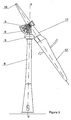
- the compensated motor torque wind turbine which is recommended, consists of a single blade turbine with a rotor (1) preferably located to leeward of the tower (8), as shown in figure 1 , being alternatively also located to windward through appropriate variations to its structure, for example through a boomerang-shaped design.
- Said rotor (1) is oscillating, cushioned by elastomers (10) located in the periphery of the fork (16) coupled to a slow speed shaft (3) which goes through a spindle (2) which holds a multiplier (5), a generator (6), and a brake disc (13), through a first bearing (4) that allows them to balance until compensating, in its angular motion, the torque and releasing the nacelle (9) from this stress.
- the multiplier set (5), generator (6) and brake disc (13) form the pendulum or pendulum set (28).
- the nacelle (9) formed by two halves in a lentil shape in which interior, the hydraulic components, control cabinets and gear motors (14) in charge of orientating the turbine in the start phase through engaging it with the inner ring of another gear bearing (7) flanged to the end of the tower (8), are housed.
- crank arm (15) is placed, to which upper end the spindle (2) is attached and crossed by the low speed shaft (3) that aligns the rotor (1) with the pendulum set (28) through two bearings, one is the rotor bearing (18) and the other one is the bearing (4) that holds the pendulum (28).
- the oscillating rotor (1) is formed by the blade (12) joined to the counterweight (18) through the hub (17) by means of flanges. Also, the hub (17) joins through its central part the mobile ring of the joint (19) which it crosses it through an exterior flange.
- a 28m rotor (1) diameter turbine in a single bladed execution, able to capture 200 Kw a 11 m/s when it rotates at 64.8 rpm with a torque of 2947 daNm, is given as an example.
- the pendulum set is determined and dimensioned, which is going to compensate looking for the appropriate mass disposition (multiplier (5), generator (6), and brake disc (13)) so that, placed at a convenient distance (pendulum crank arm), the torque is balanced to a determined angle.
- Multip.Slow speed shaft 279.20 14.89 1.00 6.59 14.89 Multip.Interm ediate shaft 180.80 4.10 4.00 26.36 65.60 Multip.counte rshaft 204.00 6.76 4.00 26.36 108.16 Multip.Fast speed shaft 102.40 0.95 23.50 154.87 524.64 Internal flywheel 649.20 54.70 23.50 154.87 30,208.08 Brake disc 106.55 7.00 23.50 154.87 3,865.75 Generator rotor 300.00 3.60 23.50 154.87 1,988.10 TOTAL MASS ROTATING PARTS 1,822.15 MOMENT OF INERTIA REDUCED TO THE LOW SPEED SHAFT (Rotating parts of the pendulum) (A) 36,775.21 MOMENT OF INERTIA OF THE WIND TURBINE ROTOR 26,000.00 TOTAL MOMENT OF INERTIA OF THE POWER TRAIN ROTATING PARTS 62,775.21 Pen
- the invention recommends a compensated motor torque wind turbine that has the particularity of arranging the elements that form the power train, that is, the multiplier (5), the generator (6), and the brake disc (13) in a pendulum way, being suspended from the spindle (2) through a first bearing (4) aligned with the rotor (1) shaft (3) so that they can rotate, compensating, in its angular motion, the torque handled by the rotor (1) until balancing it avoiding said torque to be transferred to the nacelle (9), tower (8) and shoe, which stay uncharged.
- This pendulum set accumulates potential energy when rising in its angular motion and it releases it when the gust stops and descends rotating in opposite direction of the turbine's rotor (1) rotation, restituting turns to the generator's rotor (6), being this effect a power regulator that will tend to uniform the amount of energy in the grid, smoothing the peaks and valleys through passive mechanical means.
- the turbine has a flywheel (11) located aligned with the shaft of the generator (6) that can be located both in the multiplier (5) or in its the exterior, acting as a brake disc (13) and in any case, always in the fast speed shaft (29).
- the power transmission between the rotor (1) and the low speed shaft (3) is done by oscillating ties through forks (16) and joint (19).
- the oscillation of the joint is limited to ⁇ 10°, by means of a set of elastomers (10) to the oscillation shaft (w-w) of the rotor (1).
- the fork (16) and joint (19) set allows transmitting the torque and the shaft thrust for each balance angle, providing the set with a degree of freedom that avoids the transmission of tilting moments derived from the difference in speeds of the wind, as the blade (12) goes at different ground heights in its rotation movement.
- crown and worm screw integrated in the joint (19), in which the crown constitutes the mobile ring (21) of a double ball bearing, carved in its central part, and the worm screw (20) is integrated in the exterior ring, fixed, of the bearing forming the joint (19) as shown in figure 4 .
- the hub (17) of the rotor (1) is flanged. This mechanism allows controlling the propeller passing to adjust the power captured by the turbine when being triggered by a hydraulic or electrical engine.
- the hub (17) serves as a connection between the blade (12) and the counterweight (18). These three elements form the rotor (1).
- the turbine of the invention provides for having a reversible execution geared motor brake (14), which engaged through a pinion, on the bearing inner ring (7) that holds the nacelle (9), governs the position of it until the machine connects to the grid.
- the motor brake is unblocked releasing the set of the nacelle (9), as it is a self geared turbine.
- This gear motor-brake (14) is used to unwind, when necessary, the cables that form the loop inside the tower (8), or to position the nacelle (9) where desired, for example in maintenance operations.
- a oil hydraulic central (25) will be placed on the multiplier (5), where the generator (6) was previously placed, the central (25) being part, along with the multiplier (5), of the pendulum set (28) in place of the generator (6) that is located at the base of the tower.
- the generator (6) will be placed at the foot of the tower (8), where it will be part of the stabilization kit composed by a second flywheel (22) attached to the generator (6) passing shaft, being both activated through a oil hydraulic servomotor (23) of variable cylinder, through a hydraulic coupler (24).
- This stabilizing kit will be optional and will be flanged between the shoe's base and the base of the tower (8), both bases with flanges of the same size, providing more height to the rotor (1) shaft.
- This application will be of interest when generating energy in a more uniform way, especially in isolated applications or when the generator (6) is connected to weak grids.
- the pump (27) would go submerged in depth and its shaft operated through the flywheel (22), by cardan transmission.
- the torque compensation, a multiplier (5) with spaced parallel shafts will be designed, which will allow increasing the lever arm, so that the compensating masses (generator (6) + flywheel (11)) are not excessive.
- this multiplier (5) (see figure 4 ) held from a concentric bearing with the motor shaft that allows it to balance, compensating in its angular motion said torque, is designed with two multiplying stages, the first one formed by a multiplier with an epicyclical design of three or more satellites, suitable to support the high entry torques and a second stage formed by a chain transmission, suitable to separate the distance between shafts.
- said flywheel (11) On the fast speed shaft (29) and inside the multiplier itself (5), said flywheel (11) will be placed, that besides acting as a counterweight, it will uniform the turning speed of it and therefore the speed of the generator shaft to which is attached directly.
- the brake disc (13) On the other end of the fast speed shaft (29) the brake disc (13) is located.
Landscapes
- Engineering & Computer Science (AREA)
- Life Sciences & Earth Sciences (AREA)
- Sustainable Development (AREA)
- Sustainable Energy (AREA)
- Chemical & Material Sciences (AREA)
- Combustion & Propulsion (AREA)
- Mechanical Engineering (AREA)
- General Engineering & Computer Science (AREA)
- Physics & Mathematics (AREA)
- Fluid Mechanics (AREA)
- Wind Motors (AREA)
Claims (7)
- KOMPENSIERTEN MOTOR TORQUE WINDKRAFTANLAGE, von der Art, von einer einzigen Blattrotor gebildet (1) mit einer Einzelklinge (12), die an einer Abtriebswelle (3), die durch eine Spindel geht (2) gehalten frm eine Gondel (9 ) auf der Spitze des Turms platziert auf einem Getriebelager (7) (8) angeordnet, mittels der entsprechenden Schuh angebracht ist, dadurch gekennzeichnet, dass sie die Elemente aufweist, die den Antriebsstrang bilden, das heißt, der Multiplikator (5) der Generator (6) und die Bremsscheibe (13) von der Gondel aufgehängt (9) durch ein erstes Lager (4) mit dem Rotor (1) Welle (3) bilden einer Pendelsatz (28) ausgerichtet ist, die ihnen erlaubt, drehen, kompensieren, in seiner Winkelbewegung, das Drehmoment des Rotors (1), bis es die Vermeidung dieser Ausgleich Drehmoment (9) an der Gondel übertragen werden, der Turm (8) und der Schuh; daß das Pendel ser (28) potentielle Energie sammelt, wenn in seiner Winkelbewegung steigt und es freigibt, wenn der Windstoß stoppt und steigt un entgegengesetzte Richtung des turbine's Rotor (1) Umdrehung dreht, dreht sich Rückgabe an den Rotor generator's (6) dieser Effekt ein Leistungsregler, die zu einheitlichen die Menge an Energie in das Netz neigen wird, die Spitzen und Täler durch passive mechanische Mittel zu glätten.
- KOMPENSIERTEN MOTOR TORQUE WINDKRAFTANLAGE, nach Anspruch 1, dadurch gekennzeichnet, dass die Struktur und Konfiguration des Pendels Satz (28) so ist, daß die Trägheit der rotierenden Teile der Komponenten, die den Antriebsstrang bilden, sind höher als die Trägheit der Masse des Pendels selbst eingestellt (28).
- KOMPENSIERTEN MOTOR TORQUE WINDKRAFTANLAGE, nach den Ansprüchen 1 und 2, dadurch gekennzeichnet, daß der Multiplikator (5) paralleler Wellen von besonders langen Ausführung hergestellt ist, gebildet durch zwei oder mehr Multiplikationsstufen, wobei die langsame Stufe des Planeten Design ist mit drei oder mehr Satelliten, geeignet zu übertragen das Drehmoment und die schnelle Phase ein Kettengetriebe ist, das extra lange Ausführung und weil auf der Hochgeschwindigkeitswelle (29) ein Schwungrad (11), die Drehzahlstabilität verleiht und erhöht die Trägheit der rotierenden Teile geeignet zu erreichen, so dass in im Falle einer Störung des Drehmoments betrifft dies die Pendel-Set (28), ohne die Geschwindigkeit Einheitlichkeit des Generators (6) Welle zu stören.
- KOMPENSIERTEN MOTOR TORQUE WINDKRAFTANLAGE, nach den Ansprüchen 1 bis 3, dadurch gekennzeichnet, dass der Rotor (1) eine Stech oszillierenden Rotor durch Elastomere (10) abgefedert ist, die zwischen Gabel (16) und Gelenk (19), mit Dieder von 155° in Bedingungen nominal ist, wenn im dynamischen Gleichgewicht auf der Seite, von der Dealignment der Klinge (12) und Gegengewicht (18) Masse und auf der anderen Seite, die destabilisierende Moment erzeugt durch die resultierende der Wind Axialschub erzeugt das stabilisierende Moment.
- KOMPENSIERTEN MOTOR TORQUE WINDKRAFTANLAGE, nach den Ansprüchen 1 bis 4, dadurch gekennzeichnet, dass der Durchgang des Propellers zu steuern, gibt es einen Mechanismus der Schraube Krone und Wurm in das Gelenk integriert (19), in dem die Krone des mobilen Ring (21) aus einem Doppelkugel bildet Lager in seinem mittleren Teil geschnitzt, und die Schnecke (20) in dem äußeren Ring, fest, des Lagers bildet das Gelenk (19) integriert ist; auf dem mobilen Ring (21) der Nabe (17) des Rotors (1) angeflanscht ist.
- KOMPENSIERTEN MOTOR TORQUE WINDKRAFTANLAGE, nach den Ansprüchen 1 bis 5, dadurch gekennzeichnet, dass die Gondel (9) mit elliptischem Querschnitt durch zwei Hälften verschweißt in einer Linsenform, in dem Innenraum, die hydraulischen Komponenten, Schaltschränke und Getriebemotoren untergebracht sind gebildet ist; und von der Gondel (9) und ein Teil des sich bildenden , einem Kurbelarm (15), dass hält die Spindel (2), der Rotor (1) und dem Pendelsatz (28), wird in Lee platziert.
- KOMPENSIERTEN MOTOR TORQUE WINDKRAFTANLAGE, nach einem der Ansprüche 1,2,3,5 und 6, dass in einer Ausführungsform mit einer größeren Gleichmäßigkeit und Qualität der Energieversorgung gekennzeichnet, daß ein hydrostatisches Getriebe zwischen dem Multiplizierer (5) und dem Generator (6) eingesetzt ist, so dass die Generator (6) in einer durchgehenden Welle Versionen, gelegen auf einer zweiten Schwungrad angebracht ist (22), die beide an der Basis des Turms (8), wobei durch einen ölhydraulischen Servomotor (23) variabler Zylinder durch einen hydraulischen Koppler aktiviert ( 24); sagte bildet eine Stabilisierung Satz festgelegt; und auf dem Multiplizierer (5) eine ölhydraulische Zentral (25) montiert ist, ein Teil des Pendels Satz (28) anstelle des Generators (6) bildet, die an der Basis des Turms angeordnet ist.
Applications Claiming Priority (1)
| Application Number | Priority Date | Filing Date | Title |
|---|---|---|---|
| PCT/ES2009/000348 WO2011000975A1 (es) | 2009-06-30 | 2009-06-30 | Turbina eólica de par motor compensado |
Publications (3)
| Publication Number | Publication Date |
|---|---|
| EP2458199A1 EP2458199A1 (de) | 2012-05-30 |
| EP2458199A4 EP2458199A4 (de) | 2013-12-18 |
| EP2458199B1 true EP2458199B1 (de) | 2016-04-13 |
Family
ID=43410512
Family Applications (1)
| Application Number | Title | Priority Date | Filing Date |
|---|---|---|---|
| EP09846732.7A Not-in-force EP2458199B1 (de) | 2009-06-30 | 2009-06-30 | Windturbine mit kompensiertem motordrehmoment |
Country Status (11)
| Country | Link |
|---|---|
| US (1) | US8841794B2 (de) |
| EP (1) | EP2458199B1 (de) |
| JP (1) | JP5704464B2 (de) |
| CN (1) | CN102803713B (de) |
| AU (1) | AU2009349161B2 (de) |
| CL (1) | CL2011003238A1 (de) |
| EA (1) | EA022481B1 (de) |
| ES (1) | ES2582785T3 (de) |
| MX (1) | MX353575B (de) |
| WO (1) | WO2011000975A1 (de) |
| ZA (1) | ZA201108736B (de) |
Families Citing this family (21)
| Publication number | Priority date | Publication date | Assignee | Title |
|---|---|---|---|---|
| FR2949834B1 (fr) * | 2009-09-10 | 2011-10-07 | Conseil Et Tech | Dispositif amortisseur |
| US8410627B2 (en) * | 2009-10-30 | 2013-04-02 | Stephen F. Cowap | Self orienting vertical axis wind turbine |
| US9517388B2 (en) * | 2009-12-07 | 2016-12-13 | Uncharted Play, Inc. | Energy storing device and method of using the same |
| CN103291545B (zh) * | 2012-02-22 | 2017-10-31 | 王梦川 | 可用于风电机的叶轮偏航系统 |
| WO2013155277A1 (en) * | 2012-04-11 | 2013-10-17 | Flodesign Wind Turbine Corp. | Shrouded fluid turbine with active and passive yaw control |
| EP2674618B1 (de) * | 2012-06-14 | 2016-05-04 | Siemens Aktiengesellschaft | Gondeltestvorrichtung |
| RU2516732C2 (ru) * | 2012-08-31 | 2014-05-20 | Борис Петрович Хозяинов | Способ регулирования угловой скорости вращения ветротурбины с вертикальной осью |
| RU2502893C1 (ru) * | 2012-08-31 | 2013-12-27 | Борис Петрович Хозяинов | Способ регулирования величины вращающего момента, угловой скорости вращения вертикально-осевой ветротурбины |
| US9691078B2 (en) | 2012-09-21 | 2017-06-27 | Uncharted Play, Inc. | System for incentivizing charitable giving based on physical activity and a method of using the same |
| DE102012220502A1 (de) * | 2012-11-09 | 2014-06-12 | Wobben Properties Gmbh | Windenergieanlage |
| CN104100463B (zh) * | 2013-04-07 | 2016-02-10 | 沈元明 | 重力势能风力机 |
| EP3001029B1 (de) * | 2014-09-26 | 2018-12-12 | GE Renewable Technologies Wind B.V. | Gegengewichtssysteme für eine Windturbine und Verfahren |
| US10274048B2 (en) | 2016-04-04 | 2019-04-30 | Christopher Drew | Gear system |
| RU2669722C2 (ru) * | 2016-11-08 | 2018-10-15 | Федеральное государственное бюджетное образовательное учреждение высшего образования "Воронежский государственный технический университет" | Ветроэнергетическая установка |
| CN106870282B (zh) * | 2017-03-30 | 2018-09-21 | 湘电风能有限公司 | 一种阵风下风电机组降载控制方法 |
| EP3705717A1 (de) * | 2019-03-04 | 2020-09-09 | Siemens Gamesa Renewable Energy A/S | Fundament für eine windturbine sowie windturbine |
| US10975732B2 (en) * | 2019-04-04 | 2021-04-13 | General Electric Company | Rotor turning device for balancing a wind turbine rotor |
| KR102130094B1 (ko) | 2019-04-09 | 2020-07-03 | 두산중공업 주식회사 | 풍력 발전기 |
| WO2023229467A1 (en) * | 2022-05-23 | 2023-11-30 | World Wide Wind Tech As | Wind turbine and wind power plant |
| CN116085192A (zh) * | 2023-01-18 | 2023-05-09 | 中国船舶重工集团海装风电股份有限公司 | 一种风电机组低速轴扭矩监控方法、装置及设备 |
| CN120578197B (zh) * | 2025-07-31 | 2025-09-26 | 长沙湘电电气技术有限公司 | 基于高速永磁同步电机的飞行器姿态辅助制动控制系统 |
Family Cites Families (17)
| Publication number | Priority date | Publication date | Assignee | Title |
|---|---|---|---|---|
| DE2844262A1 (de) * | 1978-10-11 | 1980-04-17 | Franz Xaver Prof Dr I Wortmann | Einblattrotor fuer windturbinen |
| DE3204541A1 (de) * | 1982-02-10 | 1983-08-25 | Franz Xaver Prof. Dr.-Ing. 7030 Böblingen Wortmann | Einblattwindturbine flair mit elastischen gliedern und mechanischen regel- und sicherheitseinrichtungen |
| CN1009020B (zh) * | 1988-02-29 | 1990-08-01 | 达亚能源有限公司 | 风力涡轮桨距控制毂 |
| US4863350A (en) * | 1988-11-18 | 1989-09-05 | Quarterman Edward A | Air turbine |
| JP3029106U (ja) * | 1996-03-18 | 1996-09-27 | 正孝 伊沢 | 風力発電機における風力回転装置 |
| ES2163362B1 (es) * | 1999-11-29 | 2003-04-01 | Ecotecnia Societat Cooperativa | Aerogenerador. |
| JP2001173549A (ja) * | 1999-12-17 | 2001-06-26 | Yamaha Motor Co Ltd | 風力変換装置 |
| DE10038602B4 (de) * | 2000-08-08 | 2013-03-28 | AEROGIE Verwaltungs GmbH | Einblattvielpolwindkonverter |
| ES2179785B1 (es) * | 2001-06-12 | 2006-10-16 | Ivan Lahuerta Antoune | Turbina eolica autotimonante. |
| NZ513769A (en) * | 2001-08-24 | 2001-09-28 | William Currie | A wind turbine |
| JP4159894B2 (ja) * | 2003-02-06 | 2008-10-01 | サクサ株式会社 | 発電設備及び発電設備における油圧装置 |
| EP1706637B1 (de) * | 2003-12-09 | 2014-02-12 | New World Generation Inc. | Windturbine zur erzeugung von elektrizität |
| JP2006077747A (ja) * | 2004-09-01 | 2006-03-23 | Iwata Kozo | 複式一枚羽根風力発電装置 |
| JP2006083839A (ja) * | 2004-09-18 | 2006-03-30 | Moriwaki Seisakusho:Kk | 水平軸風車用トルクアーム発電装置及びその制御方法 |
| JP2006249982A (ja) * | 2005-03-09 | 2006-09-21 | Mitsubishi Heavy Ind Ltd | 風力発電装置 |
| AU2008328829B2 (en) * | 2007-11-28 | 2013-08-22 | Vestas Wind Systems A/S | Method for damping oscillations in a wind turbine |
| US8277184B2 (en) * | 2010-04-22 | 2012-10-02 | General Electric Company | Tilt adjustment system |
-
2009
- 2009-06-30 EP EP09846732.7A patent/EP2458199B1/de not_active Not-in-force
- 2009-06-30 AU AU2009349161A patent/AU2009349161B2/en not_active Ceased
- 2009-06-30 EA EA201101046A patent/EA022481B1/ru unknown
- 2009-06-30 MX MX2012000008A patent/MX353575B/es active IP Right Grant
- 2009-06-30 JP JP2012516804A patent/JP5704464B2/ja not_active Expired - Fee Related
- 2009-06-30 US US13/319,528 patent/US8841794B2/en active Active - Reinstated
- 2009-06-30 CN CN200980160211.9A patent/CN102803713B/zh not_active Expired - Fee Related
- 2009-06-30 WO PCT/ES2009/000348 patent/WO2011000975A1/es not_active Ceased
- 2009-06-30 ES ES09846732.7T patent/ES2582785T3/es active Active
-
2011
- 2011-11-29 ZA ZA2011/08736A patent/ZA201108736B/en unknown
- 2011-12-21 CL CL2011003238A patent/CL2011003238A1/es unknown
Also Published As
| Publication number | Publication date |
|---|---|
| US8841794B2 (en) | 2014-09-23 |
| AU2009349161A1 (en) | 2012-01-19 |
| EP2458199A1 (de) | 2012-05-30 |
| JP2012531552A (ja) | 2012-12-10 |
| CN102803713B (zh) | 2017-04-12 |
| MX2012000008A (es) | 2012-05-08 |
| ES2582785T3 (es) | 2016-09-15 |
| US20120133148A1 (en) | 2012-05-31 |
| CN102803713A (zh) | 2012-11-28 |
| MX353575B (es) | 2018-01-19 |
| EA022481B1 (ru) | 2016-01-29 |
| WO2011000975A1 (es) | 2011-01-06 |
| JP5704464B2 (ja) | 2015-04-22 |
| CL2011003238A1 (es) | 2012-07-06 |
| EA201101046A1 (ru) | 2012-10-30 |
| EP2458199A4 (de) | 2013-12-18 |
| ZA201108736B (en) | 2013-03-27 |
| AU2009349161B2 (en) | 2015-07-16 |
Similar Documents
| Publication | Publication Date | Title |
|---|---|---|
| EP2458199B1 (de) | Windturbine mit kompensiertem motordrehmoment | |
| US4692094A (en) | Rotary positionable installation | |
| CN108194274B (zh) | 用于支撑载荷的桁架式塔 | |
| CN1796774B (zh) | 用于风力涡轮机的振动载荷降低系统 | |
| CN101427023B (zh) | 直接驱动的风力涡轮机 | |
| DK177730B1 (en) | Partial pitch wind turbine with floating foundation | |
| US10451029B2 (en) | Dual rotor wind power assembly (variants) | |
| NZ203146A (en) | Wind-generator with horizontal rotor axis and auxiliary vanes to control pitch/speed | |
| EP3027902B1 (de) | Windturbine | |
| CN1668846A (zh) | 风力发电设备及其轴承组件 | |
| US4773824A (en) | Rotor of a wind power installation | |
| KR20110118096A (ko) | 틸트 조정 시스템 | |
| US20130189105A1 (en) | Vibration absorbing device for a wind turbine and method of absorbing vibrations in a wind turbine | |
| CN105909462A (zh) | 大型双风轮风力发电机组 | |
| CN110892154A (zh) | 具有承载转子叶片的变桨马达的立式风力发电设备以及用于其的安装套件和用于其运行的方法 | |
| EP2802775A1 (de) | Getriebe | |
| JP2015513628A (ja) | 風力タービンロータ | |
| US20030015877A1 (en) | Wind power plant | |
| EP1902216B1 (de) | Windturbine mit ladungstragender schicht | |
| KR102275378B1 (ko) | 멀티형 풍력 발전기 및 멀티형 풍력 발전기의 요잉 방법 | |
| WO2004031579A1 (en) | Power generation device | |
| KR102009596B1 (ko) | 멀티형 풍력 발전기 및 이의 제어 방법 | |
| RU2351794C1 (ru) | Прецессирующий ветродвигатель с вертикальным расположением вала | |
| US20260117819A1 (en) | Bearing arrangement for a wind turbine | |
| RU2338922C2 (ru) | Прецессирующий ветродвигатель с горизонтальным расположением вала |
Legal Events
| Date | Code | Title | Description |
|---|---|---|---|
| PUAI | Public reference made under article 153(3) epc to a published international application that has entered the european phase |
Free format text: ORIGINAL CODE: 0009012 |
|
| 17P | Request for examination filed |
Effective date: 20111025 |
|
| AK | Designated contracting states |
Kind code of ref document: A1 Designated state(s): AT BE BG CH CY CZ DE DK EE ES FI FR GB GR HR HU IE IS IT LI LT LU LV MC MK MT NL NO PL PT RO SE SI SK TR |
|
| DAX | Request for extension of the european patent (deleted) | ||
| A4 | Supplementary search report drawn up and despatched |
Effective date: 20131114 |
|
| RIC1 | Information provided on ipc code assigned before grant |
Ipc: F03D 7/02 20060101ALI20131108BHEP Ipc: F03D 1/06 20060101AFI20131108BHEP Ipc: F03D 11/02 20060101ALI20131108BHEP |
|
| GRAP | Despatch of communication of intention to grant a patent |
Free format text: ORIGINAL CODE: EPIDOSNIGR1 |
|
| INTG | Intention to grant announced |
Effective date: 20151008 |
|
| GRAS | Grant fee paid |
Free format text: ORIGINAL CODE: EPIDOSNIGR3 |
|
| GRAA | (expected) grant |
Free format text: ORIGINAL CODE: 0009210 |
|
| RIC1 | Information provided on ipc code assigned before grant |
Ipc: F03D 15/00 20160101ALI20160224BHEP Ipc: F03D 7/02 20060101ALI20160224BHEP Ipc: F03D 1/06 20060101AFI20160224BHEP |
|
| AK | Designated contracting states |
Kind code of ref document: B1 Designated state(s): AT BE BG CH CY CZ DE DK EE ES FI FR GB GR HR HU IE IS IT LI LT LU LV MC MK MT NL NO PL PT RO SE SI SK TR |
|
| REG | Reference to a national code |
Ref country code: GB Ref legal event code: FG4D |
|
| REG | Reference to a national code |
Ref country code: AT Ref legal event code: REF Ref document number: 790444 Country of ref document: AT Kind code of ref document: T Effective date: 20160415 Ref country code: CH Ref legal event code: EP |
|
| REG | Reference to a national code |
Ref country code: IE Ref legal event code: FG4D |
|
| REG | Reference to a national code |
Ref country code: DE Ref legal event code: R096 Ref document number: 602009037877 Country of ref document: DE |
|
| REG | Reference to a national code |
Ref country code: FR Ref legal event code: PLFP Year of fee payment: 8 |
|
| REG | Reference to a national code |
Ref country code: LT Ref legal event code: MG4D |
|
| REG | Reference to a national code |
Ref country code: ES Ref legal event code: FG2A Ref document number: 2582785 Country of ref document: ES Kind code of ref document: T3 Effective date: 20160915 Ref country code: AT Ref legal event code: MK05 Ref document number: 790444 Country of ref document: AT Kind code of ref document: T Effective date: 20160413 |
|
| REG | Reference to a national code |
Ref country code: NL Ref legal event code: MP Effective date: 20160413 |
|
| PG25 | Lapsed in a contracting state [announced via postgrant information from national office to epo] |
Ref country code: NL Free format text: LAPSE BECAUSE OF FAILURE TO SUBMIT A TRANSLATION OF THE DESCRIPTION OR TO PAY THE FEE WITHIN THE PRESCRIBED TIME-LIMIT Effective date: 20160413 Ref country code: LT Free format text: LAPSE BECAUSE OF FAILURE TO SUBMIT A TRANSLATION OF THE DESCRIPTION OR TO PAY THE FEE WITHIN THE PRESCRIBED TIME-LIMIT Effective date: 20160413 Ref country code: FI Free format text: LAPSE BECAUSE OF FAILURE TO SUBMIT A TRANSLATION OF THE DESCRIPTION OR TO PAY THE FEE WITHIN THE PRESCRIBED TIME-LIMIT Effective date: 20160413 Ref country code: PL Free format text: LAPSE BECAUSE OF FAILURE TO SUBMIT A TRANSLATION OF THE DESCRIPTION OR TO PAY THE FEE WITHIN THE PRESCRIBED TIME-LIMIT Effective date: 20160413 Ref country code: NO Free format text: LAPSE BECAUSE OF FAILURE TO SUBMIT A TRANSLATION OF THE DESCRIPTION OR TO PAY THE FEE WITHIN THE PRESCRIBED TIME-LIMIT Effective date: 20160713 |
|
| PG25 | Lapsed in a contracting state [announced via postgrant information from national office to epo] |
Ref country code: PT Free format text: LAPSE BECAUSE OF FAILURE TO SUBMIT A TRANSLATION OF THE DESCRIPTION OR TO PAY THE FEE WITHIN THE PRESCRIBED TIME-LIMIT Effective date: 20160816 Ref country code: HR Free format text: LAPSE BECAUSE OF FAILURE TO SUBMIT A TRANSLATION OF THE DESCRIPTION OR TO PAY THE FEE WITHIN THE PRESCRIBED TIME-LIMIT Effective date: 20160413 Ref country code: AT Free format text: LAPSE BECAUSE OF FAILURE TO SUBMIT A TRANSLATION OF THE DESCRIPTION OR TO PAY THE FEE WITHIN THE PRESCRIBED TIME-LIMIT Effective date: 20160413 Ref country code: LV Free format text: LAPSE BECAUSE OF FAILURE TO SUBMIT A TRANSLATION OF THE DESCRIPTION OR TO PAY THE FEE WITHIN THE PRESCRIBED TIME-LIMIT Effective date: 20160413 Ref country code: SE Free format text: LAPSE BECAUSE OF FAILURE TO SUBMIT A TRANSLATION OF THE DESCRIPTION OR TO PAY THE FEE WITHIN THE PRESCRIBED TIME-LIMIT Effective date: 20160413 |
|
| PG25 | Lapsed in a contracting state [announced via postgrant information from national office to epo] |
Ref country code: IT Free format text: LAPSE BECAUSE OF FAILURE TO SUBMIT A TRANSLATION OF THE DESCRIPTION OR TO PAY THE FEE WITHIN THE PRESCRIBED TIME-LIMIT Effective date: 20160413 Ref country code: BE Free format text: LAPSE BECAUSE OF FAILURE TO SUBMIT A TRANSLATION OF THE DESCRIPTION OR TO PAY THE FEE WITHIN THE PRESCRIBED TIME-LIMIT Effective date: 20160413 |
|
| REG | Reference to a national code |
Ref country code: DE Ref legal event code: R097 Ref document number: 602009037877 Country of ref document: DE |
|
| PG25 | Lapsed in a contracting state [announced via postgrant information from national office to epo] |
Ref country code: DK Free format text: LAPSE BECAUSE OF FAILURE TO SUBMIT A TRANSLATION OF THE DESCRIPTION OR TO PAY THE FEE WITHIN THE PRESCRIBED TIME-LIMIT Effective date: 20160413 Ref country code: MC Free format text: LAPSE BECAUSE OF FAILURE TO SUBMIT A TRANSLATION OF THE DESCRIPTION OR TO PAY THE FEE WITHIN THE PRESCRIBED TIME-LIMIT Effective date: 20160413 Ref country code: CZ Free format text: LAPSE BECAUSE OF FAILURE TO SUBMIT A TRANSLATION OF THE DESCRIPTION OR TO PAY THE FEE WITHIN THE PRESCRIBED TIME-LIMIT Effective date: 20160413 Ref country code: EE Free format text: LAPSE BECAUSE OF FAILURE TO SUBMIT A TRANSLATION OF THE DESCRIPTION OR TO PAY THE FEE WITHIN THE PRESCRIBED TIME-LIMIT Effective date: 20160413 Ref country code: SK Free format text: LAPSE BECAUSE OF FAILURE TO SUBMIT A TRANSLATION OF THE DESCRIPTION OR TO PAY THE FEE WITHIN THE PRESCRIBED TIME-LIMIT Effective date: 20160413 Ref country code: RO Free format text: LAPSE BECAUSE OF FAILURE TO SUBMIT A TRANSLATION OF THE DESCRIPTION OR TO PAY THE FEE WITHIN THE PRESCRIBED TIME-LIMIT Effective date: 20160413 |
|
| REG | Reference to a national code |
Ref country code: CH Ref legal event code: PL |
|
| PLBE | No opposition filed within time limit |
Free format text: ORIGINAL CODE: 0009261 |
|
| STAA | Information on the status of an ep patent application or granted ep patent |
Free format text: STATUS: NO OPPOSITION FILED WITHIN TIME LIMIT |
|
| 26N | No opposition filed |
Effective date: 20170116 |
|
| REG | Reference to a national code |
Ref country code: IE Ref legal event code: MM4A |
|
| PG25 | Lapsed in a contracting state [announced via postgrant information from national office to epo] |
Ref country code: LI Free format text: LAPSE BECAUSE OF NON-PAYMENT OF DUE FEES Effective date: 20160630 Ref country code: CH Free format text: LAPSE BECAUSE OF NON-PAYMENT OF DUE FEES Effective date: 20160630 |
|
| PG25 | Lapsed in a contracting state [announced via postgrant information from national office to epo] |
Ref country code: SI Free format text: LAPSE BECAUSE OF FAILURE TO SUBMIT A TRANSLATION OF THE DESCRIPTION OR TO PAY THE FEE WITHIN THE PRESCRIBED TIME-LIMIT Effective date: 20160413 Ref country code: IE Free format text: LAPSE BECAUSE OF NON-PAYMENT OF DUE FEES Effective date: 20160630 |
|
| REG | Reference to a national code |
Ref country code: FR Ref legal event code: PLFP Year of fee payment: 9 |
|
| PG25 | Lapsed in a contracting state [announced via postgrant information from national office to epo] |
Ref country code: HU Free format text: LAPSE BECAUSE OF FAILURE TO SUBMIT A TRANSLATION OF THE DESCRIPTION OR TO PAY THE FEE WITHIN THE PRESCRIBED TIME-LIMIT; INVALID AB INITIO Effective date: 20090630 Ref country code: CY Free format text: LAPSE BECAUSE OF FAILURE TO SUBMIT A TRANSLATION OF THE DESCRIPTION OR TO PAY THE FEE WITHIN THE PRESCRIBED TIME-LIMIT Effective date: 20160413 |
|
| PG25 | Lapsed in a contracting state [announced via postgrant information from national office to epo] |
Ref country code: GR Free format text: LAPSE BECAUSE OF FAILURE TO SUBMIT A TRANSLATION OF THE DESCRIPTION OR TO PAY THE FEE WITHIN THE PRESCRIBED TIME-LIMIT Effective date: 20160413 Ref country code: LU Free format text: LAPSE BECAUSE OF NON-PAYMENT OF DUE FEES Effective date: 20160630 Ref country code: MT Free format text: LAPSE BECAUSE OF NON-PAYMENT OF DUE FEES Effective date: 20160630 Ref country code: TR Free format text: LAPSE BECAUSE OF FAILURE TO SUBMIT A TRANSLATION OF THE DESCRIPTION OR TO PAY THE FEE WITHIN THE PRESCRIBED TIME-LIMIT Effective date: 20160413 Ref country code: MK Free format text: LAPSE BECAUSE OF FAILURE TO SUBMIT A TRANSLATION OF THE DESCRIPTION OR TO PAY THE FEE WITHIN THE PRESCRIBED TIME-LIMIT Effective date: 20160413 Ref country code: IS Free format text: LAPSE BECAUSE OF FAILURE TO SUBMIT A TRANSLATION OF THE DESCRIPTION OR TO PAY THE FEE WITHIN THE PRESCRIBED TIME-LIMIT Effective date: 20160413 |
|
| PG25 | Lapsed in a contracting state [announced via postgrant information from national office to epo] |
Ref country code: BG Free format text: LAPSE BECAUSE OF FAILURE TO SUBMIT A TRANSLATION OF THE DESCRIPTION OR TO PAY THE FEE WITHIN THE PRESCRIBED TIME-LIMIT Effective date: 20160413 |
|
| REG | Reference to a national code |
Ref country code: FR Ref legal event code: PLFP Year of fee payment: 10 |
|
| PGFP | Annual fee paid to national office [announced via postgrant information from national office to epo] |
Ref country code: ES Payment date: 20190805 Year of fee payment: 11 |
|
| REG | Reference to a national code |
Ref country code: DE Ref legal event code: R082 Ref document number: 602009037877 Country of ref document: DE Representative=s name: KELLER SCHNEIDER PATENTANWALTS GMBH, DE Ref country code: DE Ref legal event code: R082 Ref document number: 602009037877 Country of ref document: DE Representative=s name: K&P PATENTANWALTSGESELLSCHAFT MBH, DE Ref country code: DE Ref legal event code: R082 Ref document number: 602009037877 Country of ref document: DE Representative=s name: K & P PATENTANWALTSGESELLSCHAFT MBH, DE |
|
| REG | Reference to a national code |
Ref country code: DE Ref legal event code: R082 Ref document number: 602009037877 Country of ref document: DE Representative=s name: KELLER SCHNEIDER PATENTANWALTS GMBH, DE Ref country code: DE Ref legal event code: R082 Ref document number: 602009037877 Country of ref document: DE Representative=s name: K & P PATENTANWALTSGESELLSCHAFT MBH, DE |
|
| REG | Reference to a national code |
Ref country code: ES Ref legal event code: FD2A Effective date: 20211228 |
|
| PG25 | Lapsed in a contracting state [announced via postgrant information from national office to epo] |
Ref country code: ES Free format text: LAPSE BECAUSE OF NON-PAYMENT OF DUE FEES Effective date: 20200701 |
|
| PGFP | Annual fee paid to national office [announced via postgrant information from national office to epo] |
Ref country code: FR Payment date: 20230629 Year of fee payment: 15 |
|
| PGFP | Annual fee paid to national office [announced via postgrant information from national office to epo] |
Ref country code: GB Payment date: 20230703 Year of fee payment: 15 |
|
| PGFP | Annual fee paid to national office [announced via postgrant information from national office to epo] |
Ref country code: DE Payment date: 20231108 Year of fee payment: 15 |
|
| REG | Reference to a national code |
Ref country code: DE Ref legal event code: R119 Ref document number: 602009037877 Country of ref document: DE |
|
| GBPC | Gb: european patent ceased through non-payment of renewal fee |
Effective date: 20240630 |
|
| PG25 | Lapsed in a contracting state [announced via postgrant information from national office to epo] |
Ref country code: DE Free format text: LAPSE BECAUSE OF NON-PAYMENT OF DUE FEES Effective date: 20250101 |
|
| PG25 | Lapsed in a contracting state [announced via postgrant information from national office to epo] |
Ref country code: FR Free format text: LAPSE BECAUSE OF NON-PAYMENT OF DUE FEES Effective date: 20240630 |
|
| PG25 | Lapsed in a contracting state [announced via postgrant information from national office to epo] |
Ref country code: GB Free format text: LAPSE BECAUSE OF NON-PAYMENT OF DUE FEES Effective date: 20240630 |