EP2458285A1 - Dispositif d'éclairage pour plaque de cuisson avec panneau céramique en verre - Google Patents
Dispositif d'éclairage pour plaque de cuisson avec panneau céramique en verre Download PDFInfo
- Publication number
- EP2458285A1 EP2458285A1 EP10015017A EP10015017A EP2458285A1 EP 2458285 A1 EP2458285 A1 EP 2458285A1 EP 10015017 A EP10015017 A EP 10015017A EP 10015017 A EP10015017 A EP 10015017A EP 2458285 A1 EP2458285 A1 EP 2458285A1
- Authority
- EP
- European Patent Office
- Prior art keywords
- illumination device
- reflector
- diffuser screen
- cover element
- cooking hob
- Prior art date
- Legal status (The legal status is an assumption and is not a legal conclusion. Google has not performed a legal analysis and makes no representation as to the accuracy of the status listed.)
- Granted
Links
Images




Classifications
-
- F—MECHANICAL ENGINEERING; LIGHTING; HEATING; WEAPONS; BLASTING
- F21—LIGHTING
- F21V—FUNCTIONAL FEATURES OR DETAILS OF LIGHTING DEVICES OR SYSTEMS THEREOF; STRUCTURAL COMBINATIONS OF LIGHTING DEVICES WITH OTHER ARTICLES, NOT OTHERWISE PROVIDED FOR
- F21V33/00—Structural combinations of lighting devices with other articles, not otherwise provided for
- F21V33/0004—Personal or domestic articles
- F21V33/0044—Household appliances, e.g. washing machines or vacuum cleaners
-
- F—MECHANICAL ENGINEERING; LIGHTING; HEATING; WEAPONS; BLASTING
- F24—HEATING; RANGES; VENTILATING
- F24C—DOMESTIC STOVES OR RANGES ; DETAILS OF DOMESTIC STOVES OR RANGES, OF GENERAL APPLICATION
- F24C7/00—Stoves or ranges heated by electric energy
- F24C7/08—Arrangement or mounting of control or safety devices
- F24C7/082—Arrangement or mounting of control or safety devices on ranges, e.g. control panels, illumination
-
- F—MECHANICAL ENGINEERING; LIGHTING; HEATING; WEAPONS; BLASTING
- F21—LIGHTING
- F21V—FUNCTIONAL FEATURES OR DETAILS OF LIGHTING DEVICES OR SYSTEMS THEREOF; STRUCTURAL COMBINATIONS OF LIGHTING DEVICES WITH OTHER ARTICLES, NOT OTHERWISE PROVIDED FOR
- F21V13/00—Producing particular characteristics or distribution of the light emitted by means of a combination of elements specified in two or more of main groups F21V1/00 - F21V11/00
- F21V13/02—Combinations of only two kinds of elements
- F21V13/04—Combinations of only two kinds of elements the elements being reflectors and refractors
-
- F—MECHANICAL ENGINEERING; LIGHTING; HEATING; WEAPONS; BLASTING
- F24—HEATING; RANGES; VENTILATING
- F24C—DOMESTIC STOVES OR RANGES ; DETAILS OF DOMESTIC STOVES OR RANGES, OF GENERAL APPLICATION
- F24C15/00—Details
- F24C15/10—Tops, e.g. hot plates; Rings
- F24C15/102—Tops, e.g. hot plates; Rings electrically heated
-
- H—ELECTRICITY
- H01—ELECTRIC ELEMENTS
- H01H—ELECTRIC SWITCHES; RELAYS; SELECTORS; EMERGENCY PROTECTIVE DEVICES
- H01H13/00—Switches having rectilinearly-movable operating part or parts adapted for pushing or pulling in one direction only, e.g. push-button switch
- H01H13/02—Details
- H01H13/023—Light-emitting indicators
-
- H—ELECTRICITY
- H01—ELECTRIC ELEMENTS
- H01H—ELECTRIC SWITCHES; RELAYS; SELECTORS; EMERGENCY PROTECTIVE DEVICES
- H01H2219/00—Legends
- H01H2219/054—Optical elements
- H01H2219/056—Diffuser; Uneven surface
-
- H—ELECTRICITY
- H01—ELECTRIC ELEMENTS
- H01H—ELECTRIC SWITCHES; RELAYS; SELECTORS; EMERGENCY PROTECTIVE DEVICES
- H01H2219/00—Legends
- H01H2219/054—Optical elements
- H01H2219/06—Reflector
Definitions
- the present invention relates to an illumination device for a cooking hob with a glass ceramic panel according to claim 1. Further, the present invention relates to a cooking hob with a glass ceramic panel and at least one illumination device according to claim 14.
- the cooking zone, the switches and the displays on a glass ceramic panel of a cooking hob are typically indicated by printed symbols. It would be especially aesthetic, if the indicating symbols would vanish in the switch-off state of the cooking hob. This can be realized be electrically illuminated cooking zones, switches and displays on the glass ceramic panel of the cooking hob. However, there are usually non-uniform illuminations and spots on the glass ceramic panel.
- the object of the present invention is achieved by the illumination device according to claim 1.
- an illumination device for a cooking hob with a glass ceramic panel, wherein:
- the main idea of the present invention is the arrangement of the components of the illumination device.
- the diffuser screen which is smaller than the reflector, allows that the lateral light beams pass said diffuser screen and propagate directly from the light source to the cover element.
- central light beams are scattered by the diffuser screen, so that the intensity in the central portion is reduced. This results in a uniform intensity distribution of the light on the cover element.
- a circuit board is arranged or arrangable at the lower open side of the reflector, wherein the light source is attached on said circuit board.
- the reflector is made of plastics.
- the inner side of the reflector may be coated by reflective material.
- the diffuser screen is made of polycarbonate.
- the cover element is made of silicone.
- the light source includes a number of light emitting diodes.
- the reflector may comprise snap-fits at its lower side for fastening the circuit board.
- the reflector and the snap-fits may be formed as a single-piece part, so that the fastening of the circuit board may be performed without any tools and further fastening means.
- the reflector may comprise means for aligning the diffuser screen in its central portion.
- the reflector and the means for aligning the diffuser screen may also be formed as a single-piece part.
- the reflector may comprise snap-fits in its interior for fastening the diffuser screen.
- the reflector may comprise latch elements engaged or engageable with corresponding sleeve elements of the cover element in order to fasten said cover element at the reflector.
- cover element may comprise a hollow for receiving at least one temperature sensor.
- the illumination device may comprise a heat conducting element providing a heat transfer from a cooking zone of the cooking hob to the temperature sensor.
- the illumination device is provided for indicating a corresponding cooking zone of the cooking hob.
- the present invention relates to a cooking hob with a glass ceramic panel and at least one illumination device described above.
- the cooking hob is an induction cooking hob and the illumination device is arranged in the centre of a corresponding induction coil.
- FIG 1 illustrates a sectional side view of an illumination device for a cooking hob according to a preferred embodiment of the present invention.
- the illumination device is arrangable below a glass ceramics panel of the cooking hob.
- the illumination device includes a reflector 10, a circuit board 12, a cover element 14 and a diffuser screen 16.
- the reflector 10 is funnel-shaped and made of plastic.
- the plastic is opaque.
- the inner side of the reflector 10 is coated by a reflective material.
- the diffuser screen 16 is made of a semitransparent material.
- the diffuser screen 16 is made of polycarbonate.
- the cover element 14 is made of a transparent material.
- the cover element 14 is made of silicone.
- the circuit board 12 is arranged in the bottom of the reflector 10 and comprises one or more light sources.
- the illumination device includes a temperature sensor 18, a cable pair 20 and an elongated heat conducting element 22.
- FIG 2 illustrates a schematic sectional side view of the light propagation within the illumination device according to the preferred embodiment of the present invention.
- a central light beam 50 extends upwards form the circuit board 12 to the diffuser screen 16. Lateral light beams 52 extend upward to the cover element 14. The lateral light beams 52 pass by the diffuser screen 16, so that the lateral light beams 52 reach directly the cover element 14.
- the central light beam 50 is scattered by the diffuser screen 16, so that diffuse light beams 54 extend upward from diffuser screen 16 to the cover element 14.
- the diffuser screen 16 allows a uniform intensity distribution of the light on the cover element 14.
- the intensity distribution of the light would have a maximum in the centre of the cover element 14.
- FIG 3 illustrates a sectional side view of the illumination device mounted within the cooking hob according to the preferred embodiment of the present invention.
- the illumination device is arranged in the centre of an induction coil 24.
- the illumination device indicates the positions of the induction coil 24 and the corresponding cooking zone within the cooking hob.
- the induction coil 24 is arranged upon a base layer 30 of the cooking hob.
- the heat conducting element 22 extends horizontally above the induction coil 24, so that the effective temperature on the cooking zone occurs also at the temperature sensor 18.
- FIG 4 illustrates a perspective view of the reflector 14 of the illumination device according to the preferred embodiment of the present invention.
- the reflector 10 is funnel-shaped and comprises inside a number of vertical fins 26.
- the reflector 10 comprises four vertical fins 26.
- the fins 26 are provided for supporting the diffuser screen 16 in the centre of the reflector 10, so the lateral light beams 52 can pass by said diffuser screen 16.
- Two opposite fins 26 includes a snap-fit 28 in each case in order to fasten the diffuser screen 16.
- Two latch elements 42 are arranged at the upper border of the reflector 10.
- the latch elements 42 are provided for fastening the cover element 14.
- the latch elements 42 are arranged at opposite sides of the upper border of the reflector 10.
- FIG 5 illustrates a perspective view of the inverted reflector 10 of the illumination device according to the preferred embodiment of the present invention.
- the reflector 10 At its bottom the reflector 10 comprises an inclusion 32 for receiving the circuit board 12.
- Two opposite snap-fits 34 are arranged on the bottom side of the reflector for fastening the circuit board 12.
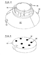
- FIG 6 illustrates a perspective view of the reflector 10 of the illumination device with an inserted diffuser screen 16 according to the preferred embodiment of the present invention.
- FIG 6 shows the reflector 10 from the same position as in FIG 4 .
- the diffuser screen 16 is inserted between the fins 26 and fixed by the snap-fits 28.
- FIG 7 illustrates a perspective view of the diffuser screen 16 according to the preferred embodiment of the present invention.
- FIG 7 clarifies that the diffuser screen 16 has the form of a circular disk.
- FIG 8 illustrates a perspective view of the inverted reflector 10 of the illumination device with an inserted circuit board 12 according to the preferred embodiment of the present invention.
- FIG 8 shows the reflector 10 from the same position as in FIG 5 .
- the circuit board 12 is inserted in the inclusion 32 and fixed by the both opposite snap-fits 34.
- FIG 9 illustrates a perspective view of the circuit board 12 for the illumination device according to the preferred embodiment of the present invention.
- a number of light emitting diodes 36 are arranged on the circuit board 12.
- the circuit board 12 comprises seven light emitting diodes 36 are arranged on the circuit board 12.
- FIG 10 illustrates a perspective view of the cover element 14 for the illumination device according to the preferred embodiment of the present invention.
- the cover element 14 has substantially the same cross section as the upper side of the reflector 10.
- the cover element 14 is made of silicone.
- the cover element 14 includes two sleeve elements 44 arranged at opposite sides of said cover element 14.
- the sleeve elements 44 are provided for receiving the corresponding latch elements 42 of the reflector 10.
- the cover element 14 is fixed at the reflector 10 by the latch elements 42 and the sleeve elements 44.
- the cover element 14 includes a hollow 38 in its upper side.
- the hollow 38 is provided for receiving a corresponding curve 40 of the heat conducting element 22.
- FIG 11 illustrates a perspective view of the reflector 10 of the illumination device with the fitted cover element 14 according to the preferred embodiment of the present invention.
- the cover element 14 is fixed at the reflector 10.
- the sleeve elements 44 of the cover element 14 have received the corresponding latch elements 42 of the reflector 10.
- FIG 12 illustrates a perspective view of the heat conducting element 22 for the illumination device according to the preferred embodiment of the present invention.
- the heat conducting element 22 includes a curve 40 corresponding with the hollow 30 in the cover element 14.
- the curve 40 is provided for receiving the temperature sensor 18, and the hollow 38 is provided for receiving the curve 40.
- the heat conducting element 22 transfers the effective temperature on the cooking zone to the temperature sensor 18.
- FIG 13 illustrates a perspective view of the reflector 10 of the illumination device with the fitted cover element 14 and heat conducting element 22 according to the preferred embodiment of the present invention.
- the heat conducting element 22 is arranged at the cover element 14.
- the curve 40 of the heat conducting element 22 is received by the hollow 38 of the cover element 14.
- FIG 14 illustrates a perspective view of the illumination device with the heat conducting element 22 and the temperature sensor 18 according to the preferred embodiment of the present invention.
- FIG. 14 is similar to FIG. 13 . Additionally, the temperature sensor 18 with the cable pair 20 is shown in FIG. 14 . The temperature sensor 18 is arranged within the curve 40 of the heat conducting element 22 and within the hollow 38 of the cover element 14.
- FIG 15 illustrates a perspective view of the reflector 10 with the diffuser screen 16 and the temperature sensor 18 according to the preferred embodiment of the present invention.
- FIG. 15 shows the illumination device of FIG. 14 without the heat conducting element 22 and the cover element 14.
- FIG. 15 clarifies that the cable pair 20 penetrates the reflector 10.
- FIG 16 illustrates a perspective view of the temperature sensor 18 with the cable pair 20 according to the preferred embodiment of the present invention.
- the cable pair 20 comprises two Z-shaped portions beside the temperature sensor 18. The Z-shaped portions allow a distance between the cable pair 20 and the heat conducting element 22.
- the illumination device of the present invention allows a simple installation of the illumination device itself and said illumination device within the cooking hob.
Landscapes
- Engineering & Computer Science (AREA)
- General Engineering & Computer Science (AREA)
- Chemical & Material Sciences (AREA)
- Combustion & Propulsion (AREA)
- Mechanical Engineering (AREA)
- Arrangement Of Elements, Cooling, Sealing, Or The Like Of Lighting Devices (AREA)
- Electric Stoves And Ranges (AREA)
- Non-Portable Lighting Devices Or Systems Thereof (AREA)
- Induction Heating Cooking Devices (AREA)
Priority Applications (5)
| Application Number | Priority Date | Filing Date | Title |
|---|---|---|---|
| EP10015017.6A EP2458285B1 (fr) | 2010-11-26 | 2010-11-26 | Plaque de cuisson avec panneau céramique en verre et un dispositif d'éclairage |
| AU2011333718A AU2011333718B2 (en) | 2010-11-26 | 2011-11-25 | An illumination device for a cooking hob with a glass ceramic panel |
| PCT/EP2011/071013 WO2012069626A1 (fr) | 2010-11-26 | 2011-11-25 | Dispositif d'éclairage pour une table de cuisson ayant un panneau en vitrocéramique |
| US13/884,349 US20130229788A1 (en) | 2010-11-26 | 2011-11-25 | Illumination device for a cooking hob with a glass ceramic panel |
| CN2011800460052A CN103119372A (zh) | 2010-11-26 | 2011-11-25 | 用于具有玻璃陶瓷面板的烹饪炉架的照明设备 |
Applications Claiming Priority (1)
| Application Number | Priority Date | Filing Date | Title |
|---|---|---|---|
| EP10015017.6A EP2458285B1 (fr) | 2010-11-26 | 2010-11-26 | Plaque de cuisson avec panneau céramique en verre et un dispositif d'éclairage |
Publications (2)
| Publication Number | Publication Date |
|---|---|
| EP2458285A1 true EP2458285A1 (fr) | 2012-05-30 |
| EP2458285B1 EP2458285B1 (fr) | 2015-09-16 |
Family
ID=43857843
Family Applications (1)
| Application Number | Title | Priority Date | Filing Date |
|---|---|---|---|
| EP10015017.6A Not-in-force EP2458285B1 (fr) | 2010-11-26 | 2010-11-26 | Plaque de cuisson avec panneau céramique en verre et un dispositif d'éclairage |
Country Status (5)
| Country | Link |
|---|---|
| US (1) | US20130229788A1 (fr) |
| EP (1) | EP2458285B1 (fr) |
| CN (1) | CN103119372A (fr) |
| AU (1) | AU2011333718B2 (fr) |
| WO (1) | WO2012069626A1 (fr) |
Cited By (5)
| Publication number | Priority date | Publication date | Assignee | Title |
|---|---|---|---|---|
| US20150013660A1 (en) * | 2012-04-02 | 2015-01-15 | Electrolux Home Products Corporation N. V. | Illumination device for a cooking zone element of a cooking hob covered by a transparent panel and a corresponding cooking zone element and cooking hob |
| ES2589837A1 (es) * | 2015-05-15 | 2016-11-16 | Bsh Electrodomésticos España, S.A. | Dispositivo de campo de cocción y procedimiento con un dispositivo de campo de cocción |
| EP3267115A1 (fr) * | 2016-07-04 | 2018-01-10 | Lg Electronics Inc. | Module de source lumineuse et appareil de cuisson le comprenant |
| ES2703023A1 (es) * | 2017-09-06 | 2019-03-06 | Bsh Electrodomesticos Espana Sa | Dispositivo de campo de coccion |
| EP3672363A1 (fr) | 2018-12-17 | 2020-06-24 | Electrolux Appliances Aktiebolag | Table de cuisson par induction comportant un équipement d'éclairage |
Families Citing this family (3)
| Publication number | Priority date | Publication date | Assignee | Title |
|---|---|---|---|---|
| US9441814B2 (en) * | 2013-02-08 | 2016-09-13 | Axis Lighting Inc. | Luminaire and output element coupling mechanism therefor |
| KR102208812B1 (ko) | 2014-05-30 | 2021-01-28 | 삼성전자주식회사 | 유도 가열 조리기기 |
| CN108072014A (zh) * | 2016-11-16 | 2018-05-25 | 佛山市顺德区美的电热电器制造有限公司 | 灯罩和面板以及烹饪器具 |
Citations (8)
| Publication number | Priority date | Publication date | Assignee | Title |
|---|---|---|---|---|
| US3786220A (en) * | 1971-12-29 | 1974-01-15 | Gen Electric | Induction cooking appliance including temperature sensing of inductively heated cooking vessel |
| WO1997036131A1 (fr) * | 1996-03-26 | 1997-10-02 | Alliedsignal Inc. | Systeme d'eclairage comprenant des microprismes pourvus de dispositifs de blocage |
| US6150636A (en) * | 1997-01-10 | 2000-11-21 | E.G.O. Elektro-Geraetebau Gmbh | Contact heat-transferring cooking system with an electric hotplate |
| EP1213543A1 (fr) * | 2000-12-08 | 2002-06-12 | Kabushiki Kaisha Toshiba | Dispositif chauffant de cuisson |
| US20020113057A1 (en) * | 2001-02-21 | 2002-08-22 | Lerner William S. | Heat alert safety device for smoothtop stoves and other hot surfaces |
| US20070223248A1 (en) * | 2006-03-27 | 2007-09-27 | Lg Philips Lcd Co., Ltd. | Light emitting diode backlight unit and liquid crystal display having the same |
| WO2009001537A1 (fr) * | 2007-06-22 | 2008-12-31 | Panasonic Corporation | Appareil de cuisson à induction |
| WO2009045041A2 (fr) * | 2007-10-02 | 2009-04-09 | Lg Electronics Inc. | Dispositif d'eclairage et appareil d'affichage pourvu de ce dispositif |
Family Cites Families (10)
| Publication number | Priority date | Publication date | Assignee | Title |
|---|---|---|---|---|
| EP2106196B1 (fr) * | 1999-12-02 | 2017-04-26 | Panasonic Corporation | Dispositif de cuisson avec chauffage par induction |
| US6969834B2 (en) * | 2001-07-03 | 2005-11-29 | Matsushita Electric Industrial Co., Ltd. | Line type luminous device and induction heating cooker employing same |
| DE10159682A1 (de) * | 2001-11-30 | 2003-06-26 | Ego Elektro Geraetebau Gmbh | Vorrichtung zur Markierung einer Induktionsspule durch Beleuchtung |
| EP2420873A3 (fr) * | 2001-12-14 | 2013-01-16 | QUALCOMM MEMS Technologies, Inc. | Système d'éclairage uniforme |
| WO2003088195A1 (fr) * | 2002-04-17 | 2003-10-23 | Kabushiki Kaisha Box | Dispositif electroluminescent de surface |
| JP4133408B2 (ja) * | 2003-02-14 | 2008-08-13 | 株式会社東芝 | 誘導加熱調理器 |
| KR101212137B1 (ko) * | 2005-08-05 | 2012-12-14 | 엘지디스플레이 주식회사 | 백라이트 유닛 |
| JP4280283B2 (ja) * | 2006-01-27 | 2009-06-17 | 株式会社オプトデザイン | 面照明光源装置及びこれを用いた面照明装置 |
| DE102007033276A1 (de) * | 2007-07-17 | 2009-01-22 | BSH Bosch und Siemens Hausgeräte GmbH | Hausgeräteeingabeeinheit, insbesondere für ein Kochfeld |
| DE102008027220A1 (de) * | 2008-06-02 | 2009-12-03 | E.G.O. Elektro-Gerätebau GmbH | Anzeigevorrichtung für ein Kochfeld, Kochfeld und Verfahren zum Betrieb einer solchen Anzeigevorrichtung |
-
2010
- 2010-11-26 EP EP10015017.6A patent/EP2458285B1/fr not_active Not-in-force
-
2011
- 2011-11-25 CN CN2011800460052A patent/CN103119372A/zh active Pending
- 2011-11-25 AU AU2011333718A patent/AU2011333718B2/en not_active Ceased
- 2011-11-25 WO PCT/EP2011/071013 patent/WO2012069626A1/fr not_active Ceased
- 2011-11-25 US US13/884,349 patent/US20130229788A1/en not_active Abandoned
Patent Citations (8)
| Publication number | Priority date | Publication date | Assignee | Title |
|---|---|---|---|---|
| US3786220A (en) * | 1971-12-29 | 1974-01-15 | Gen Electric | Induction cooking appliance including temperature sensing of inductively heated cooking vessel |
| WO1997036131A1 (fr) * | 1996-03-26 | 1997-10-02 | Alliedsignal Inc. | Systeme d'eclairage comprenant des microprismes pourvus de dispositifs de blocage |
| US6150636A (en) * | 1997-01-10 | 2000-11-21 | E.G.O. Elektro-Geraetebau Gmbh | Contact heat-transferring cooking system with an electric hotplate |
| EP1213543A1 (fr) * | 2000-12-08 | 2002-06-12 | Kabushiki Kaisha Toshiba | Dispositif chauffant de cuisson |
| US20020113057A1 (en) * | 2001-02-21 | 2002-08-22 | Lerner William S. | Heat alert safety device for smoothtop stoves and other hot surfaces |
| US20070223248A1 (en) * | 2006-03-27 | 2007-09-27 | Lg Philips Lcd Co., Ltd. | Light emitting diode backlight unit and liquid crystal display having the same |
| WO2009001537A1 (fr) * | 2007-06-22 | 2008-12-31 | Panasonic Corporation | Appareil de cuisson à induction |
| WO2009045041A2 (fr) * | 2007-10-02 | 2009-04-09 | Lg Electronics Inc. | Dispositif d'eclairage et appareil d'affichage pourvu de ce dispositif |
Cited By (12)
| Publication number | Priority date | Publication date | Assignee | Title |
|---|---|---|---|---|
| US20150013660A1 (en) * | 2012-04-02 | 2015-01-15 | Electrolux Home Products Corporation N. V. | Illumination device for a cooking zone element of a cooking hob covered by a transparent panel and a corresponding cooking zone element and cooking hob |
| US10088145B2 (en) * | 2012-04-02 | 2018-10-02 | Electrolux Home Products Corporation N.V. | Illumination device for a cooking zone element of a cooking hob covered by a transparent panel and a corresponding cooking zone element and cooking hob |
| ES2589837A1 (es) * | 2015-05-15 | 2016-11-16 | Bsh Electrodomésticos España, S.A. | Dispositivo de campo de cocción y procedimiento con un dispositivo de campo de cocción |
| WO2016185301A1 (fr) * | 2015-05-15 | 2016-11-24 | BSH Hausgeräte GmbH | Dispositif table de cuisson et procédé mettant en oeuvre un dispositif table de cuisson |
| EP3267115A1 (fr) * | 2016-07-04 | 2018-01-10 | Lg Electronics Inc. | Module de source lumineuse et appareil de cuisson le comprenant |
| CN107575907A (zh) * | 2016-07-04 | 2018-01-12 | Lg电子株式会社 | 光源单元及具有该光源单元的烹调设备 |
| CN107575907B (zh) * | 2016-07-04 | 2019-07-05 | Lg电子株式会社 | 光源单元及具有该光源单元的烹调设备 |
| US10641496B2 (en) | 2016-07-04 | 2020-05-05 | Lg Electronics Inc. | Light source unit and cooking appliance including the same |
| ES2703023A1 (es) * | 2017-09-06 | 2019-03-06 | Bsh Electrodomesticos Espana Sa | Dispositivo de campo de coccion |
| EP3672363A1 (fr) | 2018-12-17 | 2020-06-24 | Electrolux Appliances Aktiebolag | Table de cuisson par induction comportant un équipement d'éclairage |
| WO2020126467A1 (fr) | 2018-12-17 | 2020-06-25 | Electrolux Appliances Aktiebolag | Plaque de cuisson à induction dotée d'un équipement d'éclairage |
| US11497088B2 (en) | 2018-12-17 | 2022-11-08 | Electrolux Appliances Aktiebolag | Induction cooking hob with illumination equipment |
Also Published As
| Publication number | Publication date |
|---|---|
| EP2458285B1 (fr) | 2015-09-16 |
| WO2012069626A1 (fr) | 2012-05-31 |
| AU2011333718A1 (en) | 2013-04-04 |
| CN103119372A (zh) | 2013-05-22 |
| AU2011333718B2 (en) | 2015-06-04 |
| US20130229788A1 (en) | 2013-09-05 |
Similar Documents
| Publication | Publication Date | Title |
|---|---|---|
| US20130229788A1 (en) | Illumination device for a cooking hob with a glass ceramic panel | |
| AU2013242936B2 (en) | An illumination device for a cooking zone element of a cooking hob covered by a transparent panel and a corresponding cooking zone element and cooking hob | |
| US6664489B2 (en) | Touch switch with illuminated sensor element surface and light guides | |
| EP3104664B1 (fr) | Table de cuisson comprenant des moyens d'éclairage de la zone de chauffage | |
| AU2011244692B2 (en) | A cooking hob with illumination equipment | |
| KR20130138798A (ko) | 조명된 유리-세라믹 물품 | |
| US20150206669A1 (en) | Control device, in particular for a domestic appliance | |
| RU2676056C2 (ru) | Индикаторное устройство и бытовой прибор с таким индикаторным устройством | |
| KR20120102638A (ko) | 발광 다이오드를 갖는 조명 유닛 | |
| US9109803B2 (en) | Cooktop appliance with features for improving illumination | |
| EP2648478B1 (fr) | Elément d'illumination pour un élément chauffant muni d'une zone transparente sur la plaque de cuisson et l'élément chauffant | |
| CN105874276A (zh) | 家用电器操作装置 | |
| EP1985930A1 (fr) | Panneau de commande pour appareil, spécialement pour un appareil domestique | |
| CN102574739A (zh) | 具有激光-内部模槽的家用器具盖板 | |
| KR101264526B1 (ko) | 엘이디 조명장치 | |
| JP5853128B2 (ja) | 照明器具 | |
| EP2226565B1 (fr) | Plaque de cuisson avec élément d'affichage | |
| JP4386778B2 (ja) | 自動販売機の商品サンプル照明装置 | |
| EP2551229A1 (fr) | Appareil d'éclairage intérieur de cabine d'ascenseur | |
| US20160298825A1 (en) | User interface assembly for an appliance | |
| KR20070051079A (ko) | 스크래치보드 광고판 | |
| ES2747857T3 (es) | Dispositivo de visualización para un aparato eléctrico, aparato eléctrico y procedimiento para la fabricación de un tal dispositivo de visualización | |
| US11757447B2 (en) | Sensor element device for an operating device, operating device and electrical appliance having such an operating device | |
| JP5876599B2 (ja) | Led照明器具 | |
| JP5067285B2 (ja) | 加熱調理器 |
Legal Events
| Date | Code | Title | Description |
|---|---|---|---|
| PUAI | Public reference made under article 153(3) epc to a published international application that has entered the european phase |
Free format text: ORIGINAL CODE: 0009012 |
|
| 17P | Request for examination filed |
Effective date: 20110512 |
|
| AK | Designated contracting states |
Kind code of ref document: A1 Designated state(s): AL AT BE BG CH CY CZ DE DK EE ES FI FR GB GR HR HU IE IS IT LI LT LU LV MC MK MT NL NO PL PT RO RS SE SI SK SM TR |
|
| AX | Request for extension of the european patent |
Extension state: BA ME |
|
| 17Q | First examination report despatched |
Effective date: 20131213 |
|
| GRAP | Despatch of communication of intention to grant a patent |
Free format text: ORIGINAL CODE: EPIDOSNIGR1 |
|
| INTG | Intention to grant announced |
Effective date: 20150504 |
|
| GRAS | Grant fee paid |
Free format text: ORIGINAL CODE: EPIDOSNIGR3 |
|
| GRAA | (expected) grant |
Free format text: ORIGINAL CODE: 0009210 |
|
| AK | Designated contracting states |
Kind code of ref document: B1 Designated state(s): AL AT BE BG CH CY CZ DE DK EE ES FI FR GB GR HR HU IE IS IT LI LT LU LV MC MK MT NL NO PL PT RO RS SE SI SK SM TR |
|
| REG | Reference to a national code |
Ref country code: GB Ref legal event code: FG4D |
|
| REG | Reference to a national code |
Ref country code: CH Ref legal event code: EP |
|
| REG | Reference to a national code |
Ref country code: IE Ref legal event code: FG4D |
|
| REG | Reference to a national code |
Ref country code: AT Ref legal event code: REF Ref document number: 750115 Country of ref document: AT Kind code of ref document: T Effective date: 20151015 |
|
| REG | Reference to a national code |
Ref country code: DE Ref legal event code: R096 Ref document number: 602010027508 Country of ref document: DE |
|
| REG | Reference to a national code |
Ref country code: NL Ref legal event code: MP Effective date: 20150916 |
|
| PG25 | Lapsed in a contracting state [announced via postgrant information from national office to epo] |
Ref country code: LV Free format text: LAPSE BECAUSE OF FAILURE TO SUBMIT A TRANSLATION OF THE DESCRIPTION OR TO PAY THE FEE WITHIN THE PRESCRIBED TIME-LIMIT Effective date: 20150916 Ref country code: FI Free format text: LAPSE BECAUSE OF FAILURE TO SUBMIT A TRANSLATION OF THE DESCRIPTION OR TO PAY THE FEE WITHIN THE PRESCRIBED TIME-LIMIT Effective date: 20150916 Ref country code: LT Free format text: LAPSE BECAUSE OF FAILURE TO SUBMIT A TRANSLATION OF THE DESCRIPTION OR TO PAY THE FEE WITHIN THE PRESCRIBED TIME-LIMIT Effective date: 20150916 Ref country code: NO Free format text: LAPSE BECAUSE OF FAILURE TO SUBMIT A TRANSLATION OF THE DESCRIPTION OR TO PAY THE FEE WITHIN THE PRESCRIBED TIME-LIMIT Effective date: 20151216 Ref country code: GR Free format text: LAPSE BECAUSE OF FAILURE TO SUBMIT A TRANSLATION OF THE DESCRIPTION OR TO PAY THE FEE WITHIN THE PRESCRIBED TIME-LIMIT Effective date: 20151217 |
|
| REG | Reference to a national code |
Ref country code: LT Ref legal event code: MG4D |
|
| REG | Reference to a national code |
Ref country code: AT Ref legal event code: MK05 Ref document number: 750115 Country of ref document: AT Kind code of ref document: T Effective date: 20150916 |
|
| PG25 | Lapsed in a contracting state [announced via postgrant information from national office to epo] |
Ref country code: HR Free format text: LAPSE BECAUSE OF FAILURE TO SUBMIT A TRANSLATION OF THE DESCRIPTION OR TO PAY THE FEE WITHIN THE PRESCRIBED TIME-LIMIT Effective date: 20150916 Ref country code: RS Free format text: LAPSE BECAUSE OF FAILURE TO SUBMIT A TRANSLATION OF THE DESCRIPTION OR TO PAY THE FEE WITHIN THE PRESCRIBED TIME-LIMIT Effective date: 20150916 Ref country code: SE Free format text: LAPSE BECAUSE OF FAILURE TO SUBMIT A TRANSLATION OF THE DESCRIPTION OR TO PAY THE FEE WITHIN THE PRESCRIBED TIME-LIMIT Effective date: 20150916 |
|
| PG25 | Lapsed in a contracting state [announced via postgrant information from national office to epo] |
Ref country code: NL Free format text: LAPSE BECAUSE OF FAILURE TO SUBMIT A TRANSLATION OF THE DESCRIPTION OR TO PAY THE FEE WITHIN THE PRESCRIBED TIME-LIMIT Effective date: 20150916 |
|
| PG25 | Lapsed in a contracting state [announced via postgrant information from national office to epo] |
Ref country code: CZ Free format text: LAPSE BECAUSE OF FAILURE TO SUBMIT A TRANSLATION OF THE DESCRIPTION OR TO PAY THE FEE WITHIN THE PRESCRIBED TIME-LIMIT Effective date: 20150916 Ref country code: IS Free format text: LAPSE BECAUSE OF FAILURE TO SUBMIT A TRANSLATION OF THE DESCRIPTION OR TO PAY THE FEE WITHIN THE PRESCRIBED TIME-LIMIT Effective date: 20160116 Ref country code: SK Free format text: LAPSE BECAUSE OF FAILURE TO SUBMIT A TRANSLATION OF THE DESCRIPTION OR TO PAY THE FEE WITHIN THE PRESCRIBED TIME-LIMIT Effective date: 20150916 Ref country code: IT Free format text: LAPSE BECAUSE OF FAILURE TO SUBMIT A TRANSLATION OF THE DESCRIPTION OR TO PAY THE FEE WITHIN THE PRESCRIBED TIME-LIMIT Effective date: 20150916 Ref country code: ES Free format text: LAPSE BECAUSE OF FAILURE TO SUBMIT A TRANSLATION OF THE DESCRIPTION OR TO PAY THE FEE WITHIN THE PRESCRIBED TIME-LIMIT Effective date: 20150916 Ref country code: EE Free format text: LAPSE BECAUSE OF FAILURE TO SUBMIT A TRANSLATION OF THE DESCRIPTION OR TO PAY THE FEE WITHIN THE PRESCRIBED TIME-LIMIT Effective date: 20150916 |
|
| PG25 | Lapsed in a contracting state [announced via postgrant information from national office to epo] |
Ref country code: AT Free format text: LAPSE BECAUSE OF FAILURE TO SUBMIT A TRANSLATION OF THE DESCRIPTION OR TO PAY THE FEE WITHIN THE PRESCRIBED TIME-LIMIT Effective date: 20150916 Ref country code: PT Free format text: LAPSE BECAUSE OF FAILURE TO SUBMIT A TRANSLATION OF THE DESCRIPTION OR TO PAY THE FEE WITHIN THE PRESCRIBED TIME-LIMIT Effective date: 20160118 Ref country code: RO Free format text: LAPSE BECAUSE OF FAILURE TO SUBMIT A TRANSLATION OF THE DESCRIPTION OR TO PAY THE FEE WITHIN THE PRESCRIBED TIME-LIMIT Effective date: 20150916 Ref country code: PL Free format text: LAPSE BECAUSE OF FAILURE TO SUBMIT A TRANSLATION OF THE DESCRIPTION OR TO PAY THE FEE WITHIN THE PRESCRIBED TIME-LIMIT Effective date: 20150916 |
|
| REG | Reference to a national code |
Ref country code: DE Ref legal event code: R119 Ref document number: 602010027508 Country of ref document: DE |
|
| PG25 | Lapsed in a contracting state [announced via postgrant information from national office to epo] |
Ref country code: MC Free format text: LAPSE BECAUSE OF FAILURE TO SUBMIT A TRANSLATION OF THE DESCRIPTION OR TO PAY THE FEE WITHIN THE PRESCRIBED TIME-LIMIT Effective date: 20150916 Ref country code: LU Free format text: LAPSE BECAUSE OF FAILURE TO SUBMIT A TRANSLATION OF THE DESCRIPTION OR TO PAY THE FEE WITHIN THE PRESCRIBED TIME-LIMIT Effective date: 20151126 |
|
| REG | Reference to a national code |
Ref country code: CH Ref legal event code: PL |
|
| PLBE | No opposition filed within time limit |
Free format text: ORIGINAL CODE: 0009261 |
|
| STAA | Information on the status of an ep patent application or granted ep patent |
Free format text: STATUS: NO OPPOSITION FILED WITHIN TIME LIMIT |
|
| PG25 | Lapsed in a contracting state [announced via postgrant information from national office to epo] |
Ref country code: CH Free format text: LAPSE BECAUSE OF NON-PAYMENT OF DUE FEES Effective date: 20151130 Ref country code: LI Free format text: LAPSE BECAUSE OF NON-PAYMENT OF DUE FEES Effective date: 20151130 |
|
| 26N | No opposition filed |
Effective date: 20160617 |
|
| GBPC | Gb: european patent ceased through non-payment of renewal fee |
Effective date: 20151216 |
|
| REG | Reference to a national code |
Ref country code: IE Ref legal event code: MM4A |
|
| REG | Reference to a national code |
Ref country code: FR Ref legal event code: ST Effective date: 20160729 |
|
| PG25 | Lapsed in a contracting state [announced via postgrant information from national office to epo] |
Ref country code: DK Free format text: LAPSE BECAUSE OF FAILURE TO SUBMIT A TRANSLATION OF THE DESCRIPTION OR TO PAY THE FEE WITHIN THE PRESCRIBED TIME-LIMIT Effective date: 20150916 |
|
| PG25 | Lapsed in a contracting state [announced via postgrant information from national office to epo] |
Ref country code: IE Free format text: LAPSE BECAUSE OF NON-PAYMENT OF DUE FEES Effective date: 20151126 Ref country code: GB Free format text: LAPSE BECAUSE OF NON-PAYMENT OF DUE FEES Effective date: 20151216 Ref country code: DE Free format text: LAPSE BECAUSE OF NON-PAYMENT OF DUE FEES Effective date: 20160601 |
|
| PG25 | Lapsed in a contracting state [announced via postgrant information from national office to epo] |
Ref country code: FR Free format text: LAPSE BECAUSE OF NON-PAYMENT OF DUE FEES Effective date: 20151130 Ref country code: SI Free format text: LAPSE BECAUSE OF FAILURE TO SUBMIT A TRANSLATION OF THE DESCRIPTION OR TO PAY THE FEE WITHIN THE PRESCRIBED TIME-LIMIT Effective date: 20150916 |
|
| PG25 | Lapsed in a contracting state [announced via postgrant information from national office to epo] |
Ref country code: BE Free format text: LAPSE BECAUSE OF FAILURE TO SUBMIT A TRANSLATION OF THE DESCRIPTION OR TO PAY THE FEE WITHIN THE PRESCRIBED TIME-LIMIT Effective date: 20150916 |
|
| PG25 | Lapsed in a contracting state [announced via postgrant information from national office to epo] |
Ref country code: HU Free format text: LAPSE BECAUSE OF FAILURE TO SUBMIT A TRANSLATION OF THE DESCRIPTION OR TO PAY THE FEE WITHIN THE PRESCRIBED TIME-LIMIT; INVALID AB INITIO Effective date: 20101126 Ref country code: BG Free format text: LAPSE BECAUSE OF FAILURE TO SUBMIT A TRANSLATION OF THE DESCRIPTION OR TO PAY THE FEE WITHIN THE PRESCRIBED TIME-LIMIT Effective date: 20150916 Ref country code: SM Free format text: LAPSE BECAUSE OF FAILURE TO SUBMIT A TRANSLATION OF THE DESCRIPTION OR TO PAY THE FEE WITHIN THE PRESCRIBED TIME-LIMIT Effective date: 20150916 |
|
| PG25 | Lapsed in a contracting state [announced via postgrant information from national office to epo] |
Ref country code: CY Free format text: LAPSE BECAUSE OF FAILURE TO SUBMIT A TRANSLATION OF THE DESCRIPTION OR TO PAY THE FEE WITHIN THE PRESCRIBED TIME-LIMIT Effective date: 20150916 |
|
| PG25 | Lapsed in a contracting state [announced via postgrant information from national office to epo] |
Ref country code: TR Free format text: LAPSE BECAUSE OF FAILURE TO SUBMIT A TRANSLATION OF THE DESCRIPTION OR TO PAY THE FEE WITHIN THE PRESCRIBED TIME-LIMIT Effective date: 20150916 |
|
| PGFP | Annual fee paid to national office [announced via postgrant information from national office to epo] |
Ref country code: MT Payment date: 20151212 Year of fee payment: 6 |
|
| PG25 | Lapsed in a contracting state [announced via postgrant information from national office to epo] |
Ref country code: MK Free format text: LAPSE BECAUSE OF FAILURE TO SUBMIT A TRANSLATION OF THE DESCRIPTION OR TO PAY THE FEE WITHIN THE PRESCRIBED TIME-LIMIT Effective date: 20150916 |
|
| PG25 | Lapsed in a contracting state [announced via postgrant information from national office to epo] |
Ref country code: MT Free format text: LAPSE BECAUSE OF NON-PAYMENT OF DUE FEES Effective date: 20151126 |
|
| PG25 | Lapsed in a contracting state [announced via postgrant information from national office to epo] |
Ref country code: AL Free format text: LAPSE BECAUSE OF FAILURE TO SUBMIT A TRANSLATION OF THE DESCRIPTION OR TO PAY THE FEE WITHIN THE PRESCRIBED TIME-LIMIT Effective date: 20150916 |
|
| PG25 | Lapsed in a contracting state [announced via postgrant information from national office to epo] |
Ref country code: MT Free format text: LAPSE BECAUSE OF FAILURE TO SUBMIT A TRANSLATION OF THE DESCRIPTION OR TO PAY THE FEE WITHIN THE PRESCRIBED TIME-LIMIT Effective date: 20150916 |