EP2458290A2 - Küchenabzugshaube mit innovativem Design - Google Patents
Küchenabzugshaube mit innovativem Design Download PDFInfo
- Publication number
- EP2458290A2 EP2458290A2 EP11186412A EP11186412A EP2458290A2 EP 2458290 A2 EP2458290 A2 EP 2458290A2 EP 11186412 A EP11186412 A EP 11186412A EP 11186412 A EP11186412 A EP 11186412A EP 2458290 A2 EP2458290 A2 EP 2458290A2
- Authority
- EP
- European Patent Office
- Prior art keywords
- conduit
- extractor hood
- extraction
- air flow
- axis
- Prior art date
- Legal status (The legal status is an assumption and is not a legal conclusion. Google has not performed a legal analysis and makes no representation as to the accuracy of the status listed.)
- Withdrawn
Links
Images


Classifications
-
- F—MECHANICAL ENGINEERING; LIGHTING; HEATING; WEAPONS; BLASTING
- F24—HEATING; RANGES; VENTILATING
- F24C—DOMESTIC STOVES OR RANGES ; DETAILS OF DOMESTIC STOVES OR RANGES, OF GENERAL APPLICATION
- F24C15/00—Details
- F24C15/20—Removing cooking fumes
- F24C15/2028—Removing cooking fumes using an air curtain
-
- Y—GENERAL TAGGING OF NEW TECHNOLOGICAL DEVELOPMENTS; GENERAL TAGGING OF CROSS-SECTIONAL TECHNOLOGIES SPANNING OVER SEVERAL SECTIONS OF THE IPC; TECHNICAL SUBJECTS COVERED BY FORMER USPC CROSS-REFERENCE ART COLLECTIONS [XRACs] AND DIGESTS
- Y10—TECHNICAL SUBJECTS COVERED BY FORMER USPC
- Y10S—TECHNICAL SUBJECTS COVERED BY FORMER USPC CROSS-REFERENCE ART COLLECTIONS [XRACs] AND DIGESTS
- Y10S55/00—Gas separation
- Y10S55/29—Air curtains
-
- Y—GENERAL TAGGING OF NEW TECHNOLOGICAL DEVELOPMENTS; GENERAL TAGGING OF CROSS-SECTIONAL TECHNOLOGIES SPANNING OVER SEVERAL SECTIONS OF THE IPC; TECHNICAL SUBJECTS COVERED BY FORMER USPC CROSS-REFERENCE ART COLLECTIONS [XRACs] AND DIGESTS
- Y10—TECHNICAL SUBJECTS COVERED BY FORMER USPC
- Y10S—TECHNICAL SUBJECTS COVERED BY FORMER USPC CROSS-REFERENCE ART COLLECTIONS [XRACs] AND DIGESTS
- Y10S55/00—Gas separation
- Y10S55/36—Kitchen hoods
Definitions
- the present patent application for industrial invention relates to a kitchen extractor hood with new design.
- a tubular conduit with lower section (basically a chimney) is inserted on top of the shell to convey fumes towards a flue and eject them outside.
- the shell usually has a large width, which basically corresponds to the area of the cook top, in order to intercept the fumes coming from the cook top.
- the extractor hood basically consists in a simple chimney inserted directly in the flue, it being provided that the chimney directly houses the forced extraction unit for the fumes.
- the chimney has been provided internally with a powerful extraction unit with very high extraction capacity.
- the specific purpose of the present invention is to devise an extraction hood able to overcome the two aforementioned inconveniences of the prior technique. These inconveniences are overcome by an extractor hood according to claim 1.
- An extractor hood showing the features of the preamble of claim 1 is given by GB1535146A .
- the extractor hood of the invention takes inspiration from the extractor hoods without the traditional sheet metal shell, which is the most critical component in terms of aesthetics and volume.
- the extractor hood of the invention consists in a simple chimney designed to house an electrically powered extraction unit.
- the main peculiarity of this hood consists in its capability to convey the fumes from the cook top towards the mouth of the hood without the traditional sheet metal shell.
- the efficient conveyance of the fumes allows the extractor hood of the invention to be internally provided with an extraction unit with limited power (same as the ones that are currently used inside sheet metal shells of traditional extractor hoods), with benefits in terms of cost and silent operation of the same hood.
- the aforementioned inventive idea is implemented by providing two different conduits inside the structure of the new extractor hood, one of which at least housing an electrical fan unit.
- the first conduit houses an electrical extraction fan unit, which is capable of extracting air, designed to be situated in such a position that the extraction mouth is situated above the cook top.
- the second conduit blows air from inside outwards through the mouth of the same conduit.
- the air extracted by the first conduit can be blown or, alternatively, a second extraction fan unit can be used to blow air in the second conduit.
- the second conduit ends with a deflector designed to impose a basically inclined direction to the forced air flow with respect to the direction of the air extracted by the first conduit.
- the forced air flow is able to generate a sort of pneumatic screen with respect to the cook top below, which is able to intercept all ascending fumes.
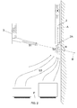
- the hood (1) which does not form part of this invention has a structure comprising two vertical conduits (2, 3) in close parallel position.
- the first conduit (2) designed to be positioned above the cook top (P) houses an electrically powered air treatment unit (4) used to extract a forced air flow (S2) inside the conduit (2) through the lower mouth (2A) of the said conduit (2).
- the second conduit (3) houses an electrically powered air treatment unit (5) designed to generate a forced air flow that comes out from the lower end of the same conduit (3) through a deflector with downward inclination (3A) on the opposite side with respect to the first conduit (2).
- the conveyance action exerted by the deflector (3A) ensures that the forced air flow coming out from the conduit (3) generates a pneumatic screen (S1) with inclined direction from up down above the cook top (P).
- the extraction mouth (2A) extracts an air flow (S2) in the direction of axis (A).
- the delivery deflector (3A) conveys a forced air flow (S1) in the direction of axis (B).
- the extraction mouth (2A) can be given any orientation in such a way that the axis (A) of the extracted air flow (S2) forms an angle from 0° to 90° with respect to a horizontal plane that basically coincides with the cook top (P).
- the extraction mouth (2A) is shown close to the wall, with axis (A) orthogonal to a horizontal plane. Nevertheless, the extraction mouth (2A) can be recessed into the wall in such a way that the axis (A) of the extracted air flow is, for instance, parallel to a horizontal plane.
- the delivery deflector (3A) can be given any orientation with respect to the extraction mouth (2A), in such a way that between the axis (A) and the axis (B) an angle ( ⁇ ) different from zero is formed.
- the angle ( ⁇ ) is included between 10° and 80°.
- the hood can be realised in wall-mounted version with a cook top installed in a cabinet positioned against the same wall, as shown in fig. 1 .
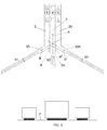
- the first conduit (2) that houses the extraction unit (4) is positioned between two specimens (3, 30) of the delivery conduit that houses the unit (5) designed to generate the outgoing forced air flow.
- the deflectors (3A, 30A) provided at the lower ends of the two specimens (3, 30) of the delivery conduit are oriented from opposite sides to create two symmetrically opposite flaps of a roof-shaped pneumatic screen (S1) above the cook top (P).
- the second conduit (3) that houses the air treatment unit (5) designed to originate one or more pneumatic screens (S1) is positioned at a certain distance from the first conduit (2).
- the deflector provided at the lower end of the second conduit (3) is directed towards the first conduit (2) at a lower height than the height of the extraction mouth (2A) of the same conduit.
- this deflector Obviously, the position and orientation given to this deflector are such that the pneumatic screen (S1) generated by it is positioned above the cook top (P), thus intercepting all fumes (S3) rising from the cook top.
- two electrical fan units are provided, one for extraction and one for delivery.
- a single motor unit with two contra-rotating fans can be provided, one for operation inside the extraction conduit (2) and one for operation inside the delivery conduit (3).
- Another alternative consists in using only one fan (4) both for extraction and delivery.
- the extraction conduit (2) is connected to the delivery conduit (3). Consequently, part of the air extracted from the fan (4) is forced into the delivery conduit (3) in order to be used to generate the pneumatic screen (S1).
- the second conduit (3) can be provided at the end, in addition to the deflector (3a), with one or more additional deflectors designed to create corresponding pneumatic screens above the cook top with intersecting directions, in order to shape and dimension the efficacy area of the multiple cooperating pneumatic screens as desired.
- the two conduits (2, 3) of the various embodiments of the extractor hood (1) may be also provided with non-vertical development (other than the hood shown in the aforementioned figures), since the only condition necessary to operate the hood (1) is that the mouth (2A) of the extraction conduit (2) is positioned above the cook top (P) and the deflector or deflectors (3A) of the delivery conduit (3) give the pneumatic screens (S1) generated by them an inclined position with angle ( ⁇ ) different from zero with respect to the axis (A) of the extracted air flow (S2).
- Fig. 4 illustrates a fourth embodiment which does not form part of this invention , whereby the extraction and delivery conduits (2, 3) are in coaxial position, one inside the other, and recessed in a vertical wall. Therefore, the axis (A) of the extracted air flow is parallel to a horizontal plane.
- the delivery deflector (3A) has a truncated-conical shape in order to generate a conical flow (S1) arranged as a shell around the extracted air flow (S2).
- the conical flow (S1) has a conicity angle ( ⁇ ) with respect to its axis that coincides with the axis (A) of the extracted air flow (S2).
- Fig. 5 illustrates a variant of the embodiment shown in Fig. 4 , whereby the axis (A) of the extracted air flow is orthogonal to a horizontal plane. This solution is appropriate when the cook top is positioned in the centre of the room and the extractor hood must be connected to the ceiling.
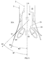
- Fig. 6 illustrates a fifth embodiment which does not form part of this invention , whereby the delivery conduit (3) is in coaxial position on the extraction conduit (2).
- the delivery conduit (3) is divided into parts by two truncated-conical deflectors (3A, 30A) that generate corresponding intersecting conical flows (S1, S4).
- the conicity angle ( ⁇ 1) of the first deflector (3A) is higher than the conicity angle ( ⁇ 2) of the second deflector in order to intersect the two conical delivery flows (S1, S2).
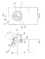
- FIGS 7 and 8 illustrate an embodiment of the present invention, whereby the delivery conduit (3) is in coaxial position on the extraction conduit (2) and the deflector (3A) has a truncated-conical shape.
- a distributor (7) with a plurality of blades (70) arranged according to an axis (C) inclined by an angle ( ⁇ ) different from zero, with respect to the radial axis (R) passing through the blade and the centre of the distributor, is mounted in the deflector (3A).
- the distributor (7) generates a pneumatic screen (S1) with helicoidal section.
- the pneumatic screen (S1) has the section of a conical helix, although it can also be given the section of a cylindrical helix.
- the angle ( ⁇ ) of the distributor blades ranges from 10° to 80°.
Landscapes
- Engineering & Computer Science (AREA)
- Chemical & Material Sciences (AREA)
- Combustion & Propulsion (AREA)
- Mechanical Engineering (AREA)
- General Engineering & Computer Science (AREA)
- Ventilation (AREA)
- Manufacture And Refinement Of Metals (AREA)
- Outer Garments And Coats (AREA)
- Prevention Of Fouling (AREA)
Applications Claiming Priority (2)
| Application Number | Priority Date | Filing Date | Title |
|---|---|---|---|
| IT000118A ITMC20070118A1 (it) | 2007-06-06 | 2007-06-06 | Cappa aspirante per cucine di innovativa concezione. |
| EP08760279A EP2165120B1 (de) | 2007-06-06 | 2008-05-30 | Küchenabzugshaube mit neuem design |
Related Parent Applications (1)
| Application Number | Title | Priority Date | Filing Date |
|---|---|---|---|
| EP08760279.3 Division | 2008-05-30 |
Publications (1)
| Publication Number | Publication Date |
|---|---|
| EP2458290A2 true EP2458290A2 (de) | 2012-05-30 |
Family
ID=39876233
Family Applications (2)
| Application Number | Title | Priority Date | Filing Date |
|---|---|---|---|
| EP11186412A Withdrawn EP2458290A2 (de) | 2007-06-06 | 2008-05-30 | Küchenabzugshaube mit innovativem Design |
| EP08760279A Active EP2165120B1 (de) | 2007-06-06 | 2008-05-30 | Küchenabzugshaube mit neuem design |
Family Applications After (1)
| Application Number | Title | Priority Date | Filing Date |
|---|---|---|---|
| EP08760279A Active EP2165120B1 (de) | 2007-06-06 | 2008-05-30 | Küchenabzugshaube mit neuem design |
Country Status (5)
| Country | Link |
|---|---|
| US (1) | US7959696B2 (de) |
| EP (2) | EP2458290A2 (de) |
| AT (1) | ATE530855T1 (de) |
| IT (1) | ITMC20070118A1 (de) |
| WO (1) | WO2008148712A2 (de) |
Cited By (1)
| Publication number | Priority date | Publication date | Assignee | Title |
|---|---|---|---|---|
| EP4443059A4 (de) * | 2021-12-06 | 2025-03-19 | LG Electronics Inc. | Bewegliche haube |
Families Citing this family (22)
| Publication number | Priority date | Publication date | Assignee | Title |
|---|---|---|---|---|
| US20100132264A1 (en) * | 2008-12-01 | 2010-06-03 | Steven Campbell | Bi-flow inflatable door seals |
| DE102009030220A1 (de) * | 2009-06-23 | 2010-12-30 | Udo Berling | Dunstabzugshaube |
| US9623506B2 (en) | 2011-02-01 | 2017-04-18 | Illinois Tool Works Inc. | Fume extractor for welding applications |
| KR20130026811A (ko) * | 2011-09-06 | 2013-03-14 | 현대자동차주식회사 | 전기자동차의 배터리 냉각덕트 필터링장치 및 필터링방법 |
| US9821351B2 (en) | 2011-11-11 | 2017-11-21 | Illinois Tool Works Inc. | Welding fume extractor |
| KR101934457B1 (ko) | 2011-11-17 | 2019-01-04 | 삼성전자주식회사 | 환기 장치와 이를 포함한 환기 시스템 |
| US9604266B2 (en) * | 2012-03-16 | 2017-03-28 | Illinois Tool Works Inc. | Airborne component extractor manifold |
| US9839948B2 (en) | 2013-01-29 | 2017-12-12 | Illinois Tool Works Inc. | Fume evacuation system |
| US9272237B2 (en) | 2013-06-28 | 2016-03-01 | Illinois Tool Works Inc. | Three-phase portable airborne component extractor with rotational direction control |
| US10808953B2 (en) | 2013-06-28 | 2020-10-20 | Illinois Tool Works Inc. | Airborne component extractor with baffled debris collection |
| US10242317B2 (en) | 2014-11-25 | 2019-03-26 | Illinois Tool Works Inc. | System for estimating the amount and content of fumes |
| US11014132B2 (en) * | 2015-07-16 | 2021-05-25 | Illinois Tool Works Inc. | Extractor with end-mounted positive pressure system |
| US11530826B2 (en) * | 2015-07-16 | 2022-12-20 | Illinois Tool Works Inc. | Extractor with segmented positive pressure airflow system |
| CN105972655A (zh) * | 2016-05-18 | 2016-09-28 | 苏州安飞荣工业科技有限公司 | 一种智能厨房 |
| IT201600071189A1 (it) * | 2016-07-07 | 2018-01-07 | B S Service S R L | Cappa aspirante per cucine con flusso direzionale. |
| WO2018008045A1 (en) * | 2016-07-07 | 2018-01-11 | B.S. Service S.R.L. | Kitchen extractor hood with directional flow |
| ES2803219T3 (es) * | 2016-07-07 | 2021-01-25 | B S Service S R L | Campana extractora de cocina con flujo en espiral |
| CN110822505B (zh) * | 2018-08-10 | 2021-05-25 | 佛山市顺德区美的洗涤电器制造有限公司 | 吸油烟机 |
| KR101985797B1 (ko) * | 2018-12-26 | 2019-09-03 | 삼성전자주식회사 | 환기 장치와 이를 포함한 환기 시스템 |
| WO2020206227A1 (en) | 2019-04-04 | 2020-10-08 | Oy Halton Group Ltd. | Slide-type range hood |
| DE102019206240A1 (de) * | 2019-04-30 | 2020-11-05 | BSH Hausgeräte GmbH | Dunstabzugsvorrichtung, Küchengerät mit Kochfeld und Dunstabzugsvorrichtung und Verfahren zum Betreiben einer Dunstabzugsvorrichtung |
| US11473783B2 (en) * | 2019-10-28 | 2022-10-18 | Lg Electronics Inc. | Kitchen hood with height adjustment |
Citations (1)
| Publication number | Priority date | Publication date | Assignee | Title |
|---|---|---|---|---|
| GB1535146A (en) | 1977-08-18 | 1978-12-06 | Jensen D | Exhaust hood for cooking or working surfaces |
Family Cites Families (19)
| Publication number | Priority date | Publication date | Assignee | Title |
|---|---|---|---|---|
| US2210458A (en) * | 1936-11-16 | 1940-08-06 | Lester S Keilholtz | Method of and apparatus for air conditioning |
| US3397631A (en) * | 1966-08-01 | 1968-08-20 | Dualjet Corp | Air curtain using ionized air |
| DE1963456A1 (de) * | 1969-12-18 | 1971-06-24 | King Maschinen Gmbh & Co Kg | Absauganlage fuer Grillstationen,Herdanlagen u.dgl. |
| US3800689A (en) * | 1972-07-24 | 1974-04-02 | L Brown | Building ventilating system |
| US4043319A (en) * | 1975-09-18 | 1977-08-23 | Jensen Donald D | Exhaust hood |
| US4186727A (en) * | 1976-01-26 | 1980-02-05 | National Food Service Equipment Fabricators, Inc. | Air ventilation and washing system |
| DE2758348C2 (de) * | 1977-12-27 | 1982-12-23 | Buderus Ag, 6330 Wetzlar | Belüftungsvorrichtung für einen Abzugschrank von Labortischen |
| DE2837543C2 (de) * | 1978-08-28 | 1984-03-15 | Miguel 8131 Berg Kling | Dunstabzugsvorrichtung |
| US4475534A (en) * | 1978-11-30 | 1984-10-09 | Moriarty Daniel J | Ventilating system for kitchen stove |
| US4483316A (en) * | 1983-10-11 | 1984-11-20 | Alco Foodservice Equipment Company | Air ventilation system |
| DE3918870C2 (de) * | 1989-06-09 | 1995-06-29 | Roehl Hager Hannelore | Verfahren und Einrichtung zum Absaugen von Dämpfen und Dunststoffen |
| CH682512A5 (de) * | 1990-03-02 | 1993-09-30 | Zurecon Ag | Dampfabzugeinrichtung. |
| JPH04327736A (ja) * | 1991-04-30 | 1992-11-17 | Mitsubishi Heavy Ind Ltd | 流体吸引ノズル及び流体処理装置 |
| DE4114329A1 (de) * | 1991-05-02 | 1992-11-05 | Standard Elektrik Lorenz Ag | Dunstabzugshaube mit luftschleier |
| DE4203916C1 (de) * | 1992-02-11 | 1993-04-29 | Hannelore 8400 Regensburg De Roehl-Hager | |
| US5713346A (en) * | 1993-08-11 | 1998-02-03 | D.E.R. Investments Ltd. | Apparatus and method for removing fumes from the space above a cooking appliance |
| US5718219A (en) * | 1997-01-10 | 1998-02-17 | Boudreault; Jean-Pierre | Kitchen exhaust hood assembly |
| US6044838A (en) * | 1999-06-05 | 2000-04-04 | Deng; David | Fume exhaust apparatus for cooking stoves |
| KR100419206B1 (ko) * | 2002-05-23 | 2004-02-21 | 삼성전자주식회사 | 벽걸이형 전자렌지 |
-
2007
- 2007-06-06 IT IT000118A patent/ITMC20070118A1/it unknown
-
2008
- 2008-05-30 EP EP11186412A patent/EP2458290A2/de not_active Withdrawn
- 2008-05-30 US US12/451,636 patent/US7959696B2/en active Active
- 2008-05-30 EP EP08760279A patent/EP2165120B1/de active Active
- 2008-05-30 AT AT08760279T patent/ATE530855T1/de not_active IP Right Cessation
- 2008-05-30 WO PCT/EP2008/056690 patent/WO2008148712A2/en not_active Ceased
Patent Citations (1)
| Publication number | Priority date | Publication date | Assignee | Title |
|---|---|---|---|---|
| GB1535146A (en) | 1977-08-18 | 1978-12-06 | Jensen D | Exhaust hood for cooking or working surfaces |
Cited By (1)
| Publication number | Priority date | Publication date | Assignee | Title |
|---|---|---|---|---|
| EP4443059A4 (de) * | 2021-12-06 | 2025-03-19 | LG Electronics Inc. | Bewegliche haube |
Also Published As
| Publication number | Publication date |
|---|---|
| US7959696B2 (en) | 2011-06-14 |
| WO2008148712A4 (en) | 2009-11-19 |
| WO2008148712A3 (en) | 2009-07-30 |
| ITMC20070118A1 (it) | 2008-12-07 |
| ATE530855T1 (de) | 2011-11-15 |
| EP2165120A2 (de) | 2010-03-24 |
| WO2008148712A2 (en) | 2008-12-11 |
| US20100126123A1 (en) | 2010-05-27 |
| EP2165120B1 (de) | 2011-10-26 |
Similar Documents
| Publication | Publication Date | Title |
|---|---|---|
| EP2165120B1 (de) | Küchenabzugshaube mit neuem design | |
| KR101625828B1 (ko) | 스월러팬을 구비한 배기장치 모듈 | |
| EP2359069B1 (de) | Absaughaube | |
| EP3550212B1 (de) | Kochgeschirr und abgasvorrichtung | |
| US10731868B2 (en) | Kitchen extractor hood with directional flow | |
| CN106065937A (zh) | 具有导风罩的传动装置 | |
| EP3507557B1 (de) | Pellettrockner mit zusätzlichem ventilator | |
| KR102247218B1 (ko) | 배기장치 및 조리기기 | |
| EP3455558B1 (de) | Dunstabzugshaube mit wirbelströmung | |
| JP2019533795A (ja) | 出口誘導プレート付きペレット乾燥機 | |
| KR20160069500A (ko) | 스월러팬을 구비한 배기장치 모듈 | |
| CN113217437B (zh) | 风扇和风扇灯 | |
| CN105157083B (zh) | 一种吸油烟机蜗壳 | |
| EP4375581B1 (de) | Kochgeschirr und abzugsvorrichtung | |
| CN102563732B (zh) | 利用旋转气流的烟雾排除装置 | |
| JP2014008484A (ja) | 粉体粉砕装置 | |
| EP2312245A2 (de) | Elektrisches Haushaltsgerät | |
| EP2607796A1 (de) | Abzugshaube mit Direktantriebsbelüftung | |
| KR20160101483A (ko) | 유체 흡입장치 | |
| CN118475777A (zh) | 泵的涡流抑制构件、泵、及泵设备 |
Legal Events
| Date | Code | Title | Description |
|---|---|---|---|
| PUAI | Public reference made under article 153(3) epc to a published international application that has entered the european phase |
Free format text: ORIGINAL CODE: 0009012 |
|
| AC | Divisional application: reference to earlier application |
Ref document number: 2165120 Country of ref document: EP Kind code of ref document: P |
|
| AK | Designated contracting states |
Kind code of ref document: A2 Designated state(s): AT BE BG CH CY CZ DE DK EE ES FI FR GB GR HR HU IE IS IT LI LT LU LV MC MT NL NO PL PT RO SE SI SK TR |
|
| STAA | Information on the status of an ep patent application or granted ep patent |
Free format text: STATUS: THE APPLICATION IS DEEMED TO BE WITHDRAWN |
|
| 18D | Application deemed to be withdrawn |
Effective date: 20131203 |