EP2458751B1 - Système et procédé de communication optique - Google Patents
Système et procédé de communication optique Download PDFInfo
- Publication number
- EP2458751B1 EP2458751B1 EP10192953.7A EP10192953A EP2458751B1 EP 2458751 B1 EP2458751 B1 EP 2458751B1 EP 10192953 A EP10192953 A EP 10192953A EP 2458751 B1 EP2458751 B1 EP 2458751B1
- Authority
- EP
- European Patent Office
- Prior art keywords
- polarization
- signal
- frequency
- laser
- pump
- Prior art date
- Legal status (The legal status is an assumption and is not a legal conclusion. Google has not performed a legal analysis and makes no representation as to the accuracy of the status listed.)
- Active
Links
Images


Classifications
-
- H—ELECTRICITY
- H04—ELECTRIC COMMUNICATION TECHNIQUE
- H04J—MULTIPLEX COMMUNICATION
- H04J14/00—Optical multiplex systems
- H04J14/06—Polarisation multiplex systems
-
- H—ELECTRICITY
- H04—ELECTRIC COMMUNICATION TECHNIQUE
- H04B—TRANSMISSION
- H04B10/00—Transmission systems employing electromagnetic waves other than radio-waves, e.g. infrared, visible or ultraviolet light, or employing corpuscular radiation, e.g. quantum communication
- H04B10/25—Arrangements specific to fibre transmission
- H04B10/2507—Arrangements specific to fibre transmission for the reduction or elimination of distortion or dispersion
- H04B10/2543—Arrangements specific to fibre transmission for the reduction or elimination of distortion or dispersion due to fibre non-linearities, e.g. Kerr effect
-
- H—ELECTRICITY
- H04—ELECTRIC COMMUNICATION TECHNIQUE
- H04B—TRANSMISSION
- H04B10/00—Transmission systems employing electromagnetic waves other than radio-waves, e.g. infrared, visible or ultraviolet light, or employing corpuscular radiation, e.g. quantum communication
- H04B10/25—Arrangements specific to fibre transmission
- H04B10/2507—Arrangements specific to fibre transmission for the reduction or elimination of distortion or dispersion
- H04B10/2569—Arrangements specific to fibre transmission for the reduction or elimination of distortion or dispersion due to polarisation mode dispersion [PMD]
-
- H—ELECTRICITY
- H04—ELECTRIC COMMUNICATION TECHNIQUE
- H04B—TRANSMISSION
- H04B10/00—Transmission systems employing electromagnetic waves other than radio-waves, e.g. infrared, visible or ultraviolet light, or employing corpuscular radiation, e.g. quantum communication
- H04B10/29—Repeaters
- H04B10/291—Repeaters in which processing or amplification is carried out without conversion of the main signal from optical form
- H04B10/2912—Repeaters in which processing or amplification is carried out without conversion of the main signal from optical form characterised by the medium used for amplification or processing
- H04B10/2916—Repeaters in which processing or amplification is carried out without conversion of the main signal from optical form characterised by the medium used for amplification or processing using Raman or Brillouin amplifiers
-
- H—ELECTRICITY
- H04—ELECTRIC COMMUNICATION TECHNIQUE
- H04B—TRANSMISSION
- H04B10/00—Transmission systems employing electromagnetic waves other than radio-waves, e.g. infrared, visible or ultraviolet light, or employing corpuscular radiation, e.g. quantum communication
- H04B10/50—Transmitters
- H04B10/516—Details of coding or modulation
- H04B10/532—Polarisation modulation
Definitions
- the invention refers to a system and a method for signal processing in a communication system (e.g. an optical communication system).
- a communication system e.g. an optical communication system
- Relatively robust and price effective on-off keying widely applied for data rates of up to 10 Gbit/s, is step by step replaced by transmission formats modulated in phase and polarization, enabling further increase of data rates to 40 Gbit/s, 100 Gbit/s and higher.
- CP-QPSK coherently-detected polarization-multiplexed quadrature phase shift keying
- the main CP-QPSK drivers are that it doubles the spectral efficiency and the total capacity, it is part of the 100G standardization according to the Optical Internetworking Forum (OIF), and all major system houses and component suppliers are currently working on CP-QPSK solutions.
- OFI Optical Internetworking Forum
- high power pump lasers for Raman amplifiers which enable a further increase of span length or idler channels which guarantee optimum EDFA operation in Dense Wavelength Division Multiplexing (DWDM) systems with limited total channel count as well as link stabilization in submarine transmission systems, or dynamically controlled Continuous Wave (CW) channels, which allow for network stabilization in case of sudden power transients (e.g. due to fiber cut).
- DWDM Dense Wavelength Division Multiplexing
- CW Continuous Wave
- the power level of the pump signal is usually higher than the average power level of the in-service data signals.
- an unpolarized CW light or a filtered ASE source is conventionally employed.
- DWDM Dense Wavelength Division Multiplexing
- OOK On Off Keying
- ODB Optical Duo Binary
- DPSK Differential Phase Shift Keying.
- DQPSK Differential Quadrature Phase Shift Keying
- modulation formats based on polarization multiplexing are sensitive to random or deterministic polarization rotations induced by cross-polarization modulation (XPolM) between the optical signals propagating along a transmission link.
- XPolM cross-polarization modulation
- Fig. 1 is a schematic representation of the application of a conventional depolarization technique.
- Fig 1 shows a combination of two delayed fractions of a single CW light 11, the first fraction over a Variable Optical Attenuator 14 and the second fraction over an optical fiber 13 characterized by a fiber length L > L coh , where L coh is the coherence length.
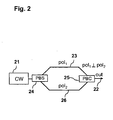
- Fig. 2 is a schematic representation of the application of a conventional depolarization technique.
- Fig 2 shows the combination 22 of two orthogonally polarized CW signals 23 and 26 from a single laser source 21. It shows also the Polarization Beam Splitter PBS 24, which splits the single laser source 21 in two orthogonally polarized CW signals 23 and 26, and a Polarization Beam Combiner PBC 25, which combines the two orthogonally polarized CW signals 23 and 26.
- Fig. 3 is a representation 31 of the degradation of the Bit Error Ratio BER 32 of a 40G CP-QPSK optical signal due to a depolarized CW channel.
- Fig 3 shows the Bit Error Ratio BER 32 of a 40G CP-QPSK optical signal versus the difference between the power of the Continuous Wave CW pump signal and the power of CP-QPSK optical signal for three different cases:
- the CW pump and 40G CP-QPSK co-propagate over a 700 km fiber link.
- the CW power level has been continuously increased relatively to the data signal.
- significant bit-error ratio degradations in the CP-QPSK signal can be observed starting at power differences of 1 dB.
- FEC threshold of 10 -3 is violated when exceeding 5 dB pump-data power difference.
- significant distortions have been detected even when the CW signal is located 2.5THz away from the CP-QPSK channel.
- a conventional depolarized CW signal causes significant penalties for polarization multiplexed data signals over a very wide spectral region, whose width depends on the power of the CW signal itself. For this reason, due to high power difference, similar distortions can be expected also from co-propagating Raman pumps, thus strongly limiting its application in optical transmission systems with polarization-multiplexed channels.
- ASE Amplified Spontaneous Emission
- Fig. 4 is a representation 41 of the degradation of the Bit Error Ratio BER 42 of a 40G CP-QPSK optical signal due to a Amplified Spontaneous Emission (ASE) source.
- Fig 4 shows the Bit Error Ratio BER 42 of a 40G CP-QPSK optical signal versus the difference between the power of the Amplified Spontaneous Emission (ASE) source and the power of CP-QPSK optical signal for three different cases:
- Cross polarization modulation effects are expected to affect not only standard coherent receivers based on digital signal processing, but also direct-detection receivers employing fast polarization controllers for input polarization demultiplexing. Indeed, current active polarization controllers can compensate only relatively slow polarization rotations (in the order of a hundred kHz) but would not be able to cope with fast polarization rotations induced by Cross Polarization Modulation (XPolM).
- XPolM Cross Polarization Modulation
- the problem to be solved is to overcome the disadvantages stated above and in particular to provide a solution that minimize the destructive Cross Polarization Modulation (XPolM) interactions in polarization-multiplexed transmission systems such as CP-QPSK.
- XPolM Cross Polarization Modulation
- an optical communication system for transmitting an optical signal, comprising a pump source configured to generate a pump signal having rotating polarization, a polarization sensitive receiver for receiving the optical signal having a polarization tracking cut-off frequency, wherein the polarization of the pump signal is configured to rotate at a predetermined frequency of polarization rotation and the frequency of polarization rotation of the pump signal is higher than the polarization tracking cut-off frequency of the receiver.
- the polarization tracking cut-off frequency can be defined as a frequency of polarization variations that leads to factor of two higher BER at the polarization sensitive receiver comparing to case without.
- the optical signal is a coherently-detected polarization-multiplexed quadrature phase shift keying (CP-QPSK) signal.
- CP-QPSK coherently-detected polarization-multiplexed quadrature phase shift keying
- system further comprises a continuous wave (CW) laser source for generating a continuous wave (CW) laser signal.
- CW continuous wave
- the system further comprises a polarization modulator for modulating the continuous wave (CW) laser signal and a radio frequency (RF) source connected with the polarization modulator for generating the polarization rotation of the pump signal.
- a polarization modulator for modulating the continuous wave (CW) laser signal
- RF radio frequency
- the system further comprises a first polarization rotator for rotating the polarization of the continuous wave (CW) laser signal and thereby generating a first component of the pump signal.
- CW continuous wave
- the system further comprises an optical phase modulator for phase-modulating the continuous wave (CW) laser signal and a radio frequency (RF) source connected with the phase modulator, the optical phase modulator being configured to generate a second component of the pump signal.
- CW continuous wave
- RF radio frequency
- the pump signal is a combination of the first component and the second component of the pump signal.
- first component and the second component of the pump signal have a different polarization with respect to each other.
- the radio frequency (RF) source is configured to adjust the frequency of polarization rotation of the pump signal.
- the system further comprises a first continuous wave (CW) laser source for generating a first continuous wave laser signal and a second continuous wave (CW) laser source for generating a second continuous wave (CW) laser signal, the first and the second continuous wave (CW) laser signals being frequency detuned with respect to each other.
- CW continuous wave
- CW continuous wave
- system further comprises a second polarization rotator coupled with the second continuous wave (CW) laser source for rotating the polarization of the second continuous wave (CW) laser signal and thereby generating a second laser signal.
- CW continuous wave
- the pump signal is a combination of the first continuous wave (CW) laser signal and the second laser signal, the first continuous wave (CW) laser signal and the second laser signal having a different polarization with respect to each other.
- the frequency of polarization rotation of the pump signal is adjustable by adjusting the frequency detuning of the first and the second continuous wave (CW) laser signals with respect to each other.
- the apparatus further includes an optical fiber link for propagating the pump signal and the optical signal.
- the polarization sensitive receiver is a coherent receiver.
- a method for transmitting an optical signal which includes: generating a pump signal having rotating polarization, transmitting the pump signal, transmitting the optical signal, receiving the optical signal by means of a polarization sensitive receiver having a polarization tracking cut-off frequency, rotating the polarization of the pump signal at a predetermined frequency of polarization rotation, the frequency of polarization rotation of the pump signal being higher than the polarization tracking cut-off frequency of the receiver.
- Fig. 5 is a schematic representation of the application of a depolarization technique for application in polarization-multiplexed transmission system according to an embodiment of the invention.
- a pump source 51 for example a Raman pump source, which includes a single CW light source 53, for example a laser source.
- the CW light source 53 generates a CW laser signal 56 which is modulated by a polarization modulator 55, in particular a fast polarization modulator, that generates the fast polarization rotation of the pump signal 52.
- the required speed of polarization rotations can be generated using the RF source 54, connected to the polarization modulator 55, which is configured to adjust the frequency of polarization rotation of the pump signal 52.
- the so generated pump signal 52 can be propagated in a fiber link together with an optical signal, for example a CP-QPSK signal.
- the optical signal and the pump signal 52 can be received by a polarization sensitive receiver having a given polarization tracking cut-off frequency.
- the ultra-fast polarization of the pump signal 52 can be adjusted in such a way that the frequency of polarization rotation of the pump signal 52 is higher than the polarization tracking cut-off frequency of the receiver.
- the spectral components of the polarization rotation can be naturally rejected by the polarization sensitive receiver, which may also be a coherent receiver.
- the polarization tracking cut-off frequency can be defined as a frequency of polarization variations that leads to factor of two higher BER at the polarization sensitive receiver comparing to case without. In this way the destructive Cross Polarization Modulation (XPolM) interactions in polarization-multiplexed transmission systems can be efficiently minimized.
- XPolM Cross Polarization Modulation
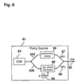
- Fig. 6 is a schematic representation of the application of a depolarization technique for application in polarization-multiplexed transmission system according to an embodiment of the invention.
- a pump source 61 for example a Raman pump source, which generates a pump signal 62, combination of a phase modulated component 68 and a phase un-modulated component 67, having different polarization, derived from a single CW laser source 63.
- An optical coupler for example a 3dB coupler (not shown in Figure 6 ) may split the single laser source 63 in two differently polarized CW signals 623 and 626. According to a different embodiment of the invention, the two CW signals 623 and 626 may be orthogonally polarized.
- An optical phase modulator 66 phase-modulates the CW signals 626, while a polarization rotator 65, rotates the polarization of the CW signal 623 relative to the CW signal 626.
- An optical coupler for example a 3dB coupler (not shown in Figure 6 ), may combine the two differently polarized CW signals 67 and 68.
- the required speed of polarization rotations can be generated using the RF source 64, connected to the optical phase modulator 66, which is configured to adjust the frequency of polarization rotation of the pump signal 62.
- the so generated pump signal 62 can be propagated in a fiber link together with an optical signal, for example a CP-QPSK signal.
- the optical signal and the pump signal 62 can be received by a polarization sensitive receiver having a polarization tracking cut-off frequency.
- the ultra-fast polarization of the pump signal 62 can be adjusted in such a way that the frequency of polarization rotation of the pump signal 62 is higher than the polarization tracking cut-off frequency of the receiver.
- the spectral components of the polarization rotation can be naturally rejected by the polarization sensitive receiver, which may also be a coherent receiver. In this way the destructive Cross Polarization Modulation (XPolM) interactions in polarization-multiplexed transmission systems can be efficiently minimized.
- XPolM destructive Cross Polarization Modulation
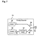
- Fig. 7 is a schematic representation of the application of a depolarization technique for application in polarization-multiplexed transmission system according to an embodiment of the invention.
- Fig 7 shows a pump source 71, for example a Raman pump source, which generates pump signal 72, combination of two frequency detuned, differently polarized CW laser signals 75 and 78 from two CW laser sources 73 and 74.
- the two CW signals 75 and 78 may be orthogonally polarized.
- a polarization rotator 77 coupled with the second continuous wave (CW) laser source 74, which rotates the polarization of the continuous wave (CW) laser signal 76 relative to the CW signal 75 thereby generating the CW signal 78.
- the fast polarization rotation is generated by combining the two laser signal 78 and 75.
- the frequency of polarization rotation of the pump signal 72 can be adjustable by adjusting the frequency detuning of the first 75 and the second 76 continuous wave (CW) laser signals with respect to each other.
- speed of polarization rotation is directly related to the frequency detuning of the two CW channels.
- the so generated pump signal 72 can be propagated in an fiber link together with an optical signal, for example a CP-QPSK signal.
- the optical signal and the pump signal 72 can be received by a polarization sensitive receiver having a polarization tracking cut-off frequency.
- the ultra-fast polarization of the pump signal 72 can be adjusted in such a way that the frequency of polarization rotation of the pump signal 72 is higher than the polarization tracking cut-off frequency of the receiver.
- the spectral components of the polarization rotation can be naturally rejected by the polarization sensitive receiver, which may also be a coherent receiver. In this way the destructive Cross Polarization Modulation (XPolM) interactions in polarization-multiplexed transmission systems can be efficiently minimized.
- XPolM destructive Cross Polarization Modulation
- the embodiment of the invention comprising the two detuned CW laser signal 75 and 78 does not require necessarily the employment of high RF electronics; furthermore, it provides a benefit related to power budget, mechanical footprint as well as cost efficiency.
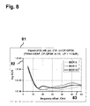
- Fig. 8 is a representation 81 of the degradation of the Bit Error Ratio BER 82 of a 40G CP-QPSK optical signal due to two orthogonally polarized, frequency detuned CW laser sources.
- Fig 8 shows the Bit Error Ratio BER 82 of a 40G CP-QPSK optical signal versus the frequency offset 83 between the two orthogonally polarized, frequency detuned CW laser sources.
- the 40G CP-QPSK receiver is characterized by a polarization tracking cut-off frequency of around 8 GHz.
- Fig. 9 is a representation 91 of the degradation of the Bit Error Ratio BER 92 of a 40G CP-QPSK optical signal due to two orthogonally polarized, frequency detuned CW laser sources.
- Fig 9 shows the Bit Error Ratio BER 92 of a 40G CP-QPSK optical signal versus the spacing 93 between the CW pump signal and the CP-QPSK signal.
- Fig. 9 shows that a frequency offset ⁇ f of 15 GHz between the two CW signals leads to distortion-free performance almost independently of the spacing between the CW pump and the CP-QPSK channel.
- the present invention allows for generic usage of optical pump sources independently on modulation format of data channels.
- a critical minimum frequency detuning For each modulation format and data rate, a critical minimum frequency detuning has to be identified individually. Theoretically, a fix value for the maximum frequency detuning cannot be established. Larger frequency offset may be beneficial for reducing of pump beating, however this may reduce the optical bandwidth available for useful channels' transmission and may leads to higher sensitivity to frequency dependent polarization changes (due to second order polarization mode dispersion, SOPMD or polarization dependent loss, PDL).
- SOPMD second order polarization mode dispersion
- PDL polarization dependent loss
- CW sources fixed laser with wavelength locker or a tunable laser can be used.
- the two CW lights have to be combined at different polarizations (preferably orthogonally polarized).
- the power level of the lasers should preferably be similar, but slight mismatches do not affect the performance significantly.
Landscapes
- Engineering & Computer Science (AREA)
- Computer Networks & Wireless Communication (AREA)
- Signal Processing (AREA)
- Physics & Mathematics (AREA)
- Electromagnetism (AREA)
- Nonlinear Science (AREA)
- Optical Communication System (AREA)
- Optical Modulation, Optical Deflection, Nonlinear Optics, Optical Demodulation, Optical Logic Elements (AREA)
Claims (15)
- Agencement pour transmettre un signal optique comprenant :une source de pompage (51, 61, 71) configurée pour générer un signal de pompage (52, 62, 72) ayant une polarisation rotatoire ;un récepteur sensible à la polarisation pour recevoir le signal optique ayant une fréquence de coupure de suivi de polarisation qui est définie en tant que fréquence de variations de polarisation qui mène à un BER deux fois plus élevé au niveau du récepteur sensible à la polarisation comparé au cas sans ;caractérisé en ce que :la polarisation du signal de pompage (52, 62, 72) est configurée pour tourner à une fréquence prédéterminée de rotation de polarisation ;la fréquence de rotation de polarisation du signal de pompage (52, 62, 72) est supérieure à la fréquence de coupure de suivi de polarisation du récepteur.
- Système selon la revendication 1, le système comprenant en outre une source laser à onde continue (CW) (53, 63) pour générer un signal laser à onde continue (CW).
- Système selon la revendication 2, le système comprenant en outre un modulateur de polarisation (55) pour moduler le signal laser à onde continue (CW) et une source radiofréquence (RF) (54) connectée au modulateur de polarisation (55) pour générer la rotation de polarisation du signal de pompage.
- Système selon la revendication 2, le système comprenant en outre un premier dispositif de rotation de polarisation (65) pour faire tourner la polarisation du signal laser à onde continue (CW) et générer de ce fait une première composante (67) du signal de pompage (62).
- Système selon la revendication 4, le système comprenant en outre un modulateur de phase optique (66) pour moduler en phase le signal laser à onde continue (CW) et une source radiofréquence (RF) (64) connectée au modulateur de phase (66), le modulateur de phase optique (66) étant configuré pour générer une deuxième composante (68) du signal de pompage (62).
- Système selon la revendication 5, le signal de pompage (62) étant une combinaison de la première composante (67) et de la deuxième composante (68) du signal de pompage (62).
- Système selon la revendication 6, la première composante (67) et la deuxième composante (68) du signal de pompage (62) ayant des polarisations différentes l'une de l'autre.
- Système selon la revendication 3 ou selon l'une quelconque des revendications 5 à 7, dans lequel la source radiofréquence (RF) (54, 64) est configurée pour ajuster la fréquence de la rotation de polarisation du signal de pompage (52, 62).
- Système selon la revendication 1, le système comprenant en outre une première source laser à onde continue (CW) (73) pour générer un premier signal laser à onde continue (CW) (75) et une deuxième source laser à onde continue (CW) (74) pour générer un deuxième signal laser à onde continue (CW) (76), les premier (75) et deuxième (76) signaux laser à onde continue (CW) étant désaccordés en fréquence l'un par rapport à l'autre.
- Système selon la revendication 8, le système comprenant en outre un deuxième dispositif de rotation de polarisation (77) couplé à la deuxième source laser à onde continue (CW) (74) pour faire tourner la polarisation du deuxième signal laser à onde continue (CW) (76) et générer de ce fait un deuxième signal laser (78).
- Système selon la revendication 10, le signal de pompage (72) étant une combinaison du premier signal laser à onde continue (CW) (75) et du deuxième signal laser (78), le premier signal laser à onde continue (CW) (75) et le deuxième signal laser (78) ayant des polarisations différentes l'une de l'autre.
- Système selon l'une quelconque des revendications 9 à 11, dans lequel la fréquence de la rotation de polarisation du signal de pompage (72) peut être ajustée en ajustant le désaccord de fréquence des premier (75) et deuxième (76) signaux laser à onde continue (CW) l'un par rapport à l'autre.
- Système selon l'une quelconque des revendications précédentes, comprenant en outre une liaison par fibre optique pour propager le signal de pompage (52, 62, 72) et le signal optique.
- Système selon l'une quelconque des revendications précédentes, le récepteur sensible à la polarisation étant un récepteur cohérent.
- Procédé pour transmettre un signal optique comprenant :la génération d'un signal de pompage (52, 62, 72) ayant une polarisation rotatoire ;la transmission du signal optique ;la transmission du signal de pompage (52, 62, 72) ;la réception du signal optique au moyen d'un récepteur sensible à la polarisation ayant une fréquence de coupure de suivi de polarisation qui est définie en tant que fréquence de variations de polarisation qui mène à un BER deux fois plus élevé au niveau du récepteur sensible à la polarisation comparé au cas sans ;caractérisé par :la rotation de la polarisation du signal de pompage (52, 62, 72) à une fréquence prédéterminée de rotation de polarisation, la fréquence de la rotation de polarisation du signal de pompage (52, 62, 72) étant plus élevée que la fréquence de coupure de suivi de polarisation du récepteur.
Priority Applications (4)
| Application Number | Priority Date | Filing Date | Title |
|---|---|---|---|
| EP10192953.7A EP2458751B1 (fr) | 2010-11-29 | 2010-11-29 | Système et procédé de communication optique |
| US13/990,371 US9490930B2 (en) | 2010-11-29 | 2011-11-28 | Optical communication system and method |
| PCT/EP2011/071110 WO2012072534A1 (fr) | 2010-11-29 | 2011-11-28 | Système et procédé de communication optique |
| CN201180066212.4A CN103329461B (zh) | 2010-11-29 | 2011-11-28 | 光学通信系统和方法 |
Applications Claiming Priority (1)
| Application Number | Priority Date | Filing Date | Title |
|---|---|---|---|
| EP10192953.7A EP2458751B1 (fr) | 2010-11-29 | 2010-11-29 | Système et procédé de communication optique |
Publications (2)
| Publication Number | Publication Date |
|---|---|
| EP2458751A1 EP2458751A1 (fr) | 2012-05-30 |
| EP2458751B1 true EP2458751B1 (fr) | 2013-11-20 |
Family
ID=43877062
Family Applications (1)
| Application Number | Title | Priority Date | Filing Date |
|---|---|---|---|
| EP10192953.7A Active EP2458751B1 (fr) | 2010-11-29 | 2010-11-29 | Système et procédé de communication optique |
Country Status (4)
| Country | Link |
|---|---|
| US (1) | US9490930B2 (fr) |
| EP (1) | EP2458751B1 (fr) |
| CN (1) | CN103329461B (fr) |
| WO (1) | WO2012072534A1 (fr) |
Families Citing this family (6)
| Publication number | Priority date | Publication date | Assignee | Title |
|---|---|---|---|---|
| EP2458751B1 (fr) * | 2010-11-29 | 2013-11-20 | Xieon Networks S.à.r.l. | Système et procédé de communication optique |
| CN104568218B (zh) * | 2014-12-26 | 2017-12-08 | 武汉理工光科股份有限公司 | 提高分布式自发拉曼散射温度传感器工作距离的方法 |
| GB201605120D0 (en) * | 2016-03-24 | 2016-05-11 | Univ Aston | System and method for the transmission of optic signals |
| US11506916B2 (en) * | 2021-04-09 | 2022-11-22 | Fujitsu Limited | Dual polarization optical pumping |
| CN115001581B (zh) * | 2022-06-16 | 2023-05-16 | 中国联合网络通信集团有限公司 | 光网络单元的光衰处理方法、设备及存储介质 |
| CN115441958B (zh) * | 2022-08-29 | 2024-04-26 | 武汉邮电科学研究院有限公司 | 一种模拟相干光通信的信号处理方法及系统 |
Family Cites Families (27)
| Publication number | Priority date | Publication date | Assignee | Title |
|---|---|---|---|---|
| US5104222A (en) * | 1990-09-18 | 1992-04-14 | The United States Of America As Represented By The Secretary Of The Navy | System and method for minimizing input polarization-induced phase noise in an interferometric fiber-optic sensor depolarized input light |
| JP3419510B2 (ja) * | 1992-10-16 | 2003-06-23 | 富士通株式会社 | 波長分散を補償した光通信システム及び該システムに適用可能な位相共役光発生装置 |
| WO1994009403A1 (fr) * | 1992-10-20 | 1994-04-28 | Fujitsu Limited | Application d'un systeme optique a une optique a conjugaison de phases |
| US5345331A (en) * | 1993-04-13 | 1994-09-06 | At&T Bell Laboratories | Technique for reducing polarization dependent gain in an amplified optical transmission system |
| EP1841022A3 (fr) * | 1995-03-20 | 2009-12-02 | Fujitsu Limited | Appareil et procédé pour le traitement d'un signal optique |
| US6175435B1 (en) * | 1995-11-22 | 2001-01-16 | Fujitsu Limited | Optical communication system using optical phase conjugation to suppress waveform distortion caused by chromatic dispersion and optical kerr effect |
| JP3566096B2 (ja) * | 1998-08-31 | 2004-09-15 | 富士通株式会社 | 位相共役変換及び波長変換のための装置 |
| US6404542B1 (en) * | 2000-07-10 | 2002-06-11 | Sdl, Inc. | Multiple emitter semiconductor laser pump source for scaling of pump power and generation of unpolarized light for light signal amplification |
| US6456426B1 (en) * | 2001-06-28 | 2002-09-24 | Onetta, Inc. | Raman amplifiers with modulated pumps |
| US6657776B2 (en) * | 2001-11-21 | 2003-12-02 | Lucent Technologies Inc. | Pump source including polarization scrambling in Raman amplified optical WDM systems |
| US6914716B2 (en) * | 2001-11-21 | 2005-07-05 | Lucent Technologies Inc. | Modulated pump source for fiber Raman amplifier |
| KR100443288B1 (ko) * | 2002-01-22 | 2004-08-09 | 한국전자통신연구원 | 밀리미터파 대역의 광 발진기 |
| US7289735B2 (en) * | 2004-04-05 | 2007-10-30 | Jds Uniphase Corporation | Apparatus for emitting light with controllable degree of polarization |
| JP4328724B2 (ja) * | 2005-01-17 | 2009-09-09 | 富士通株式会社 | 光波形測定装置および光波形測定方法 |
| US7865080B2 (en) * | 2005-01-26 | 2011-01-04 | Nokia Siemens Networks Gmbh & Co. Kg | Methods for the optical transmission of polarization multiplex signals |
| DE102005003681A1 (de) * | 2005-01-26 | 2006-08-10 | Siemens Ag | Verfahren zur optischen Datenübertragung mit Polarisations- und Wellenlängen-Multiplex |
| JP4984442B2 (ja) * | 2005-06-22 | 2012-07-25 | 富士通株式会社 | 光スイッチ装置及び光スイッチ方法 |
| US7609976B2 (en) * | 2005-09-29 | 2009-10-27 | Alcatel-Lucent Usa Inc. | Method and system for ultra-high bit rate fiber-optic communications |
| JP2007240389A (ja) * | 2006-03-09 | 2007-09-20 | Fujitsu Ltd | 光波形測定装置および光波形測定方法 |
| JP2008089781A (ja) * | 2006-09-29 | 2008-04-17 | Fujitsu Ltd | 光パラメトリック増幅装置 |
| JP4467557B2 (ja) * | 2006-12-25 | 2010-05-26 | 富士通株式会社 | 光スイッチング方法及び光スイッチ |
| JP5056095B2 (ja) * | 2007-03-20 | 2012-10-24 | 富士通株式会社 | 光波形制御装置、光信号処理装置および光中継装置 |
| US7853156B2 (en) * | 2007-10-19 | 2010-12-14 | Ciena Corporation | Systems and methods for the coherent non-differential detection of optical communication signals |
| WO2010125657A1 (fr) * | 2009-04-28 | 2010-11-04 | 富士通株式会社 | Dispositif de traitement de signaux optiques |
| US20120002283A1 (en) * | 2010-06-30 | 2012-01-05 | Chongjin Xie | Method and apparatus for raman co-pumps |
| EP2458751B1 (fr) | 2010-11-29 | 2013-11-20 | Xieon Networks S.à.r.l. | Système et procédé de communication optique |
| JP5751015B2 (ja) * | 2011-05-26 | 2015-07-22 | 富士通株式会社 | 光信号処理装置および光通信システム |
-
2010
- 2010-11-29 EP EP10192953.7A patent/EP2458751B1/fr active Active
-
2011
- 2011-11-28 WO PCT/EP2011/071110 patent/WO2012072534A1/fr not_active Ceased
- 2011-11-28 CN CN201180066212.4A patent/CN103329461B/zh active Active
- 2011-11-28 US US13/990,371 patent/US9490930B2/en active Active
Also Published As
| Publication number | Publication date |
|---|---|
| CN103329461B (zh) | 2016-03-30 |
| US20130343766A1 (en) | 2013-12-26 |
| US9490930B2 (en) | 2016-11-08 |
| WO2012072534A1 (fr) | 2012-06-07 |
| EP2458751A1 (fr) | 2012-05-30 |
| CN103329461A (zh) | 2013-09-25 |
Similar Documents
| Publication | Publication Date | Title |
|---|---|---|
| Sackey et al. | Kerr nonlinearity mitigation: mid-link spectral inversion versus digital backpropagation in 5× 28-GBd PDM 16-QAM signal transmission | |
| Masuda et al. | 13.5-Tb/s (135× 111-Gb/s/ch) no-guard-interval coherent OFDM transmission over 6,248 km using SNR maximized second-order DRA in the extended L-band | |
| Laperle et al. | Wavelength division multiplexing (WDM) and polarization mode dispersion (PMD) performance of a coherent 40Gbit/s dual-polarization quadrature phase shift keying (DP-QPSK) transceiver | |
| Zhu et al. | High spectral density long-haul 40-Gb/s transmission using CSRZ-DPSK format | |
| EP2501067B1 (fr) | Système et procédé pour réduire les interférences d'un signal de polarisation multiplexé | |
| EP2458751B1 (fr) | Système et procédé de communication optique | |
| Rosa et al. | Unrepeatered DP-QPSK transmission over 352.8 km SMF using random DFB fiber laser amplification | |
| Gaur et al. | Polarization-insensitive fibre optic parametric amplifier with gain bandwidth of 35 nm in L-band | |
| Huang et al. | Transmission of 400G dual-carrier DP-16QAM and multi-carrier DP-QPSK signals over regional and long-haul distances with span lengths greater than 200 km | |
| Bastamova et al. | Performance evaluation of a polarisation insensitive Mach-Zehnder fiber parametric amplifier with 38 channel transmission | |
| Charlet et al. | Transmission of 81 channels at 40Gbit/s over a Transpacific-Distance Erbium-only Link, using PDM-BPSK Modulation, Coherent Detection, and a new large effective area fibre. | |
| De Oliveira et al. | Hybrid EDFA/Raman amplification topology for repeaterless 4.48 Tb/s (40 112 Gb/s DP-DQPSK) transmission over 302 Km of G. 652 standard single mode fiber | |
| Salsi et al. | WDM 200Gb/s single-carrier PDM-QPSK transmission over 12,000 km | |
| Mongardien et al. | 2.6 Tb/s (26× 100Gb/s) unrepeatered transmission over 401km using PDM-QPSK with a coherent receiver | |
| Mongardien et al. | 15.4 Tb/s C-band only unrepeatered transmission of real-time processed 200 Gb/s PDM-16 QAM over 355 km | |
| Huang et al. | Real-time 8× 200-Gb/s 16-QAM unrepeatered transmission over 458.8 km using concatenated receiver-side ROPAs | |
| Yoshida et al. | Reverse phase modulation technique for GAWBS noise error floor elimination in 1024 QAM-160 km digital coherent transmission | |
| Nakamura et al. | Ultimate linewidth-tolerant 20-Gbps QPSK-homodyne transmission using a spectrum-sliced ASE light source | |
| Jia et al. | Record experimental demonstration of 800G/lane based 36-Tb/s 3150-km transmission enabled by silicon-based IC-TROSA | |
| Downie et al. | Transmission of 112 Gb/s PM-QPSK signals over 7200 km of optical fiber with very large effective area and ultra-low loss in 100 km spans with EDFAs only | |
| Xia et al. | 10,000-km enhanced long-haul transmission of 1.15-Tb/s superchannel using SSMF only | |
| Jensen et al. | XPM-induced degradation of multilevel phase modulated channel caused by neighboring NRZ modulated channels | |
| Bousselet et al. | High capacity (64× 43 Gb/s) unrepeatered transmission over 440 km | |
| Yoshida et al. | Single-channel 3.84 Tbit/s, 64 QAM coherent Nyquist pulse transmission over 150 km with frequency-stabilized and mode-locked laser | |
| Behrens et al. | Long-haul WDM transmission of PDM-8PSK and PDM-8QAM with nonlinear DSP |
Legal Events
| Date | Code | Title | Description |
|---|---|---|---|
| PUAI | Public reference made under article 153(3) epc to a published international application that has entered the european phase |
Free format text: ORIGINAL CODE: 0009012 |
|
| AK | Designated contracting states |
Kind code of ref document: A1 Designated state(s): AL AT BE BG CH CY CZ DE DK EE ES FI FR GB GR HR HU IE IS IT LI LT LU LV MC MK MT NL NO PL PT RO RS SE SI SK SM TR |
|
| AX | Request for extension of the european patent |
Extension state: BA ME |
|
| 17P | Request for examination filed |
Effective date: 20121130 |
|
| REG | Reference to a national code |
Ref country code: DE Ref legal event code: R079 Ref document number: 602010011846 Country of ref document: DE Free format text: PREVIOUS MAIN CLASS: H04B0010180000 Ipc: H04B0010254300 |
|
| GRAP | Despatch of communication of intention to grant a patent |
Free format text: ORIGINAL CODE: EPIDOSNIGR1 |
|
| RIC1 | Information provided on ipc code assigned before grant |
Ipc: H04B 10/532 20130101ALI20130529BHEP Ipc: H04B 10/291 20130101ALI20130529BHEP Ipc: H04B 10/2569 20130101ALI20130529BHEP Ipc: H04B 10/2543 20130101AFI20130529BHEP |
|
| INTG | Intention to grant announced |
Effective date: 20130628 |
|
| GRAS | Grant fee paid |
Free format text: ORIGINAL CODE: EPIDOSNIGR3 |
|
| GRAA | (expected) grant |
Free format text: ORIGINAL CODE: 0009210 |
|
| RAP1 | Party data changed (applicant data changed or rights of an application transferred) |
Owner name: NOKIA SOLUTIONS AND NETWORKS OY Owner name: FRAUNHOFER-GESELLSCHAFT ZUR FOERDERUNG DER ANGEWAN |
|
| AK | Designated contracting states |
Kind code of ref document: B1 Designated state(s): AL AT BE BG CH CY CZ DE DK EE ES FI FR GB GR HR HU IE IS IT LI LT LU LV MC MK MT NL NO PL PT RO RS SE SI SK SM TR |
|
| RAP1 | Party data changed (applicant data changed or rights of an application transferred) |
Owner name: XIEON NETWORKS S.A.R.L. Owner name: FRAUNHOFER-GESELLSCHAFT ZUR FOERDERUNG DER ANGEWAN |
|
| REG | Reference to a national code |
Ref country code: GB Ref legal event code: FG4D |
|
| REG | Reference to a national code |
Ref country code: CH Ref legal event code: EP |
|
| REG | Reference to a national code |
Ref country code: AT Ref legal event code: REF Ref document number: 642161 Country of ref document: AT Kind code of ref document: T Effective date: 20131215 |
|
| REG | Reference to a national code |
Ref country code: DE Ref legal event code: R082 Ref document number: 602010011846 Country of ref document: DE Representative=s name: BOEHMERT & BOEHMERT, DE Ref country code: DE Ref legal event code: R082 Ref document number: 602010011846 Country of ref document: DE Representative=s name: BOEHMERT & BOEHMERT ANWALTSPARTNERSCHAFT MBB -, DE |
|
| REG | Reference to a national code |
Ref country code: IE Ref legal event code: FG4D |
|
| REG | Reference to a national code |
Ref country code: DE Ref legal event code: R096 Ref document number: 602010011846 Country of ref document: DE Effective date: 20140116 |
|
| REG | Reference to a national code |
Ref country code: NL Ref legal event code: VDEP Effective date: 20131120 |
|
| REG | Reference to a national code |
Ref country code: AT Ref legal event code: MK05 Ref document number: 642161 Country of ref document: AT Kind code of ref document: T Effective date: 20131120 |
|
| REG | Reference to a national code |
Ref country code: LT Ref legal event code: MG4D |
|
| PG25 | Lapsed in a contracting state [announced via postgrant information from national office to epo] |
Ref country code: FI Free format text: LAPSE BECAUSE OF FAILURE TO SUBMIT A TRANSLATION OF THE DESCRIPTION OR TO PAY THE FEE WITHIN THE PRESCRIBED TIME-LIMIT Effective date: 20131120 Ref country code: LT Free format text: LAPSE BECAUSE OF FAILURE TO SUBMIT A TRANSLATION OF THE DESCRIPTION OR TO PAY THE FEE WITHIN THE PRESCRIBED TIME-LIMIT Effective date: 20131120 Ref country code: IS Free format text: LAPSE BECAUSE OF FAILURE TO SUBMIT A TRANSLATION OF THE DESCRIPTION OR TO PAY THE FEE WITHIN THE PRESCRIBED TIME-LIMIT Effective date: 20140320 Ref country code: HR Free format text: LAPSE BECAUSE OF FAILURE TO SUBMIT A TRANSLATION OF THE DESCRIPTION OR TO PAY THE FEE WITHIN THE PRESCRIBED TIME-LIMIT Effective date: 20131120 Ref country code: SE Free format text: LAPSE BECAUSE OF FAILURE TO SUBMIT A TRANSLATION OF THE DESCRIPTION OR TO PAY THE FEE WITHIN THE PRESCRIBED TIME-LIMIT Effective date: 20131120 Ref country code: NO Free format text: LAPSE BECAUSE OF FAILURE TO SUBMIT A TRANSLATION OF THE DESCRIPTION OR TO PAY THE FEE WITHIN THE PRESCRIBED TIME-LIMIT Effective date: 20140220 Ref country code: NL Free format text: LAPSE BECAUSE OF FAILURE TO SUBMIT A TRANSLATION OF THE DESCRIPTION OR TO PAY THE FEE WITHIN THE PRESCRIBED TIME-LIMIT Effective date: 20131120 |
|
| REG | Reference to a national code |
Ref country code: FR Ref legal event code: GC Effective date: 20140408 |
|
| PG25 | Lapsed in a contracting state [announced via postgrant information from national office to epo] |
Ref country code: BE Free format text: LAPSE BECAUSE OF FAILURE TO SUBMIT A TRANSLATION OF THE DESCRIPTION OR TO PAY THE FEE WITHIN THE PRESCRIBED TIME-LIMIT Effective date: 20131120 Ref country code: RS Free format text: LAPSE BECAUSE OF FAILURE TO SUBMIT A TRANSLATION OF THE DESCRIPTION OR TO PAY THE FEE WITHIN THE PRESCRIBED TIME-LIMIT Effective date: 20131120 Ref country code: LV Free format text: LAPSE BECAUSE OF FAILURE TO SUBMIT A TRANSLATION OF THE DESCRIPTION OR TO PAY THE FEE WITHIN THE PRESCRIBED TIME-LIMIT Effective date: 20131120 Ref country code: ES Free format text: LAPSE BECAUSE OF FAILURE TO SUBMIT A TRANSLATION OF THE DESCRIPTION OR TO PAY THE FEE WITHIN THE PRESCRIBED TIME-LIMIT Effective date: 20131120 Ref country code: AT Free format text: LAPSE BECAUSE OF FAILURE TO SUBMIT A TRANSLATION OF THE DESCRIPTION OR TO PAY THE FEE WITHIN THE PRESCRIBED TIME-LIMIT Effective date: 20131120 |
|
| PG25 | Lapsed in a contracting state [announced via postgrant information from national office to epo] |
Ref country code: PT Free format text: LAPSE BECAUSE OF FAILURE TO SUBMIT A TRANSLATION OF THE DESCRIPTION OR TO PAY THE FEE WITHIN THE PRESCRIBED TIME-LIMIT Effective date: 20140320 |
|
| PG25 | Lapsed in a contracting state [announced via postgrant information from national office to epo] |
Ref country code: EE Free format text: LAPSE BECAUSE OF FAILURE TO SUBMIT A TRANSLATION OF THE DESCRIPTION OR TO PAY THE FEE WITHIN THE PRESCRIBED TIME-LIMIT Effective date: 20131120 |
|
| REG | Reference to a national code |
Ref country code: DE Ref legal event code: R097 Ref document number: 602010011846 Country of ref document: DE |
|
| REG | Reference to a national code |
Ref country code: IE Ref legal event code: MM4A |
|
| PG25 | Lapsed in a contracting state [announced via postgrant information from national office to epo] |
Ref country code: SK Free format text: LAPSE BECAUSE OF FAILURE TO SUBMIT A TRANSLATION OF THE DESCRIPTION OR TO PAY THE FEE WITHIN THE PRESCRIBED TIME-LIMIT Effective date: 20131120 Ref country code: RO Free format text: LAPSE BECAUSE OF FAILURE TO SUBMIT A TRANSLATION OF THE DESCRIPTION OR TO PAY THE FEE WITHIN THE PRESCRIBED TIME-LIMIT Effective date: 20131120 Ref country code: CZ Free format text: LAPSE BECAUSE OF FAILURE TO SUBMIT A TRANSLATION OF THE DESCRIPTION OR TO PAY THE FEE WITHIN THE PRESCRIBED TIME-LIMIT Effective date: 20131120 Ref country code: PL Free format text: LAPSE BECAUSE OF FAILURE TO SUBMIT A TRANSLATION OF THE DESCRIPTION OR TO PAY THE FEE WITHIN THE PRESCRIBED TIME-LIMIT Effective date: 20131120 Ref country code: IT Free format text: LAPSE BECAUSE OF FAILURE TO SUBMIT A TRANSLATION OF THE DESCRIPTION OR TO PAY THE FEE WITHIN THE PRESCRIBED TIME-LIMIT Effective date: 20131120 |
|
| PLBE | No opposition filed within time limit |
Free format text: ORIGINAL CODE: 0009261 |
|
| STAA | Information on the status of an ep patent application or granted ep patent |
Free format text: STATUS: NO OPPOSITION FILED WITHIN TIME LIMIT |
|
| PG25 | Lapsed in a contracting state [announced via postgrant information from national office to epo] |
Ref country code: DK Free format text: LAPSE BECAUSE OF FAILURE TO SUBMIT A TRANSLATION OF THE DESCRIPTION OR TO PAY THE FEE WITHIN THE PRESCRIBED TIME-LIMIT Effective date: 20131120 |
|
| 26N | No opposition filed |
Effective date: 20140821 |
|
| PG25 | Lapsed in a contracting state [announced via postgrant information from national office to epo] |
Ref country code: IE Free format text: LAPSE BECAUSE OF NON-PAYMENT OF DUE FEES Effective date: 20131129 |
|
| REG | Reference to a national code |
Ref country code: DE Ref legal event code: R097 Ref document number: 602010011846 Country of ref document: DE Effective date: 20140821 |
|
| PG25 | Lapsed in a contracting state [announced via postgrant information from national office to epo] |
Ref country code: SI Free format text: LAPSE BECAUSE OF FAILURE TO SUBMIT A TRANSLATION OF THE DESCRIPTION OR TO PAY THE FEE WITHIN THE PRESCRIBED TIME-LIMIT Effective date: 20131120 |
|
| PG25 | Lapsed in a contracting state [announced via postgrant information from national office to epo] |
Ref country code: MC Free format text: LAPSE BECAUSE OF FAILURE TO SUBMIT A TRANSLATION OF THE DESCRIPTION OR TO PAY THE FEE WITHIN THE PRESCRIBED TIME-LIMIT Effective date: 20131120 |
|
| PG25 | Lapsed in a contracting state [announced via postgrant information from national office to epo] |
Ref country code: SM Free format text: LAPSE BECAUSE OF FAILURE TO SUBMIT A TRANSLATION OF THE DESCRIPTION OR TO PAY THE FEE WITHIN THE PRESCRIBED TIME-LIMIT Effective date: 20131120 |
|
| PG25 | Lapsed in a contracting state [announced via postgrant information from national office to epo] |
Ref country code: TR Free format text: LAPSE BECAUSE OF FAILURE TO SUBMIT A TRANSLATION OF THE DESCRIPTION OR TO PAY THE FEE WITHIN THE PRESCRIBED TIME-LIMIT Effective date: 20131120 Ref country code: CY Free format text: LAPSE BECAUSE OF FAILURE TO SUBMIT A TRANSLATION OF THE DESCRIPTION OR TO PAY THE FEE WITHIN THE PRESCRIBED TIME-LIMIT Effective date: 20131120 |
|
| REG | Reference to a national code |
Ref country code: CH Ref legal event code: PL |
|
| GBPC | Gb: european patent ceased through non-payment of renewal fee |
Effective date: 20141129 |
|
| PG25 | Lapsed in a contracting state [announced via postgrant information from national office to epo] |
Ref country code: MK Free format text: LAPSE BECAUSE OF FAILURE TO SUBMIT A TRANSLATION OF THE DESCRIPTION OR TO PAY THE FEE WITHIN THE PRESCRIBED TIME-LIMIT Effective date: 20131120 Ref country code: CH Free format text: LAPSE BECAUSE OF NON-PAYMENT OF DUE FEES Effective date: 20141130 Ref country code: HU Free format text: LAPSE BECAUSE OF FAILURE TO SUBMIT A TRANSLATION OF THE DESCRIPTION OR TO PAY THE FEE WITHIN THE PRESCRIBED TIME-LIMIT; INVALID AB INITIO Effective date: 20101129 Ref country code: BG Free format text: LAPSE BECAUSE OF FAILURE TO SUBMIT A TRANSLATION OF THE DESCRIPTION OR TO PAY THE FEE WITHIN THE PRESCRIBED TIME-LIMIT Effective date: 20131120 Ref country code: LI Free format text: LAPSE BECAUSE OF NON-PAYMENT OF DUE FEES Effective date: 20141130 Ref country code: LU Free format text: LAPSE BECAUSE OF NON-PAYMENT OF DUE FEES Effective date: 20131129 |
|
| PG25 | Lapsed in a contracting state [announced via postgrant information from national office to epo] |
Ref country code: MT Free format text: LAPSE BECAUSE OF FAILURE TO SUBMIT A TRANSLATION OF THE DESCRIPTION OR TO PAY THE FEE WITHIN THE PRESCRIBED TIME-LIMIT Effective date: 20131120 Ref country code: GR Free format text: LAPSE BECAUSE OF NON-PAYMENT OF DUE FEES Effective date: 20131120 |
|
| REG | Reference to a national code |
Ref country code: FR Ref legal event code: GC Effective date: 20150922 |
|
| PG25 | Lapsed in a contracting state [announced via postgrant information from national office to epo] |
Ref country code: GB Free format text: LAPSE BECAUSE OF NON-PAYMENT OF DUE FEES Effective date: 20141129 |
|
| REG | Reference to a national code |
Ref country code: FR Ref legal event code: PLFP Year of fee payment: 6 |
|
| PG25 | Lapsed in a contracting state [announced via postgrant information from national office to epo] |
Ref country code: GR Free format text: LAPSE BECAUSE OF FAILURE TO SUBMIT A TRANSLATION OF THE DESCRIPTION OR TO PAY THE FEE WITHIN THE PRESCRIBED TIME-LIMIT Effective date: 20140221 |
|
| REG | Reference to a national code |
Ref country code: FR Ref legal event code: PLFP Year of fee payment: 7 |
|
| REG | Reference to a national code |
Ref country code: FR Ref legal event code: PLFP Year of fee payment: 8 |
|
| PG25 | Lapsed in a contracting state [announced via postgrant information from national office to epo] |
Ref country code: AL Free format text: LAPSE BECAUSE OF FAILURE TO SUBMIT A TRANSLATION OF THE DESCRIPTION OR TO PAY THE FEE WITHIN THE PRESCRIBED TIME-LIMIT Effective date: 20131120 |
|
| PGFP | Annual fee paid to national office [announced via postgrant information from national office to epo] |
Ref country code: FR Payment date: 20191120 Year of fee payment: 10 |
|
| PG25 | Lapsed in a contracting state [announced via postgrant information from national office to epo] |
Ref country code: FR Free format text: LAPSE BECAUSE OF NON-PAYMENT OF DUE FEES Effective date: 20201130 |
|
| PGFP | Annual fee paid to national office [announced via postgrant information from national office to epo] |
Ref country code: DE Payment date: 20250930 Year of fee payment: 16 |