EP2458932A1 - Procédé de relais, appareil de relais et système de communication de support de transport - Google Patents
Procédé de relais, appareil de relais et système de communication de support de transport Download PDFInfo
- Publication number
- EP2458932A1 EP2458932A1 EP10807947A EP10807947A EP2458932A1 EP 2458932 A1 EP2458932 A1 EP 2458932A1 EP 10807947 A EP10807947 A EP 10807947A EP 10807947 A EP10807947 A EP 10807947A EP 2458932 A1 EP2458932 A1 EP 2458932A1
- Authority
- EP
- European Patent Office
- Prior art keywords
- base station
- signaling
- data
- encapsulated
- self
- Prior art date
- Legal status (The legal status is an assumption and is not a legal conclusion. Google has not performed a legal analysis and makes no representation as to the accuracy of the status listed.)
- Granted
Links
Images




Classifications
-
- H—ELECTRICITY
- H04—ELECTRIC COMMUNICATION TECHNIQUE
- H04W—WIRELESS COMMUNICATION NETWORKS
- H04W28/00—Network traffic management; Network resource management
- H04W28/02—Traffic management, e.g. flow control or congestion control
- H04W28/06—Optimizing the usage of the radio link, e.g. header compression, information sizing, discarding information
-
- H—ELECTRICITY
- H04—ELECTRIC COMMUNICATION TECHNIQUE
- H04W—WIRELESS COMMUNICATION NETWORKS
- H04W84/00—Network topologies
- H04W84/02—Hierarchically pre-organised networks, e.g. paging networks, cellular networks, WLAN [Wireless Local Area Network] or WLL [Wireless Local Loop]
- H04W84/04—Large scale networks; Deep hierarchical networks
- H04W84/042—Public Land Mobile systems, e.g. cellular systems
- H04W84/047—Public Land Mobile systems, e.g. cellular systems using dedicated repeater stations
Definitions
- the present invention relates to the field of communications technologies, and in particular, to a relay method of a transport bearer, an apparatus and a communication system.
- a wireless air interface bearer In a wireless communication system, in order to ensure normal receiving and sending of user data, a wireless air interface bearer generally needs to be set up between a UE and a base station, and a transport bearer is set up between the base station and a gateway; meanwhile, the wireless air interface bearer of the UE corresponds to the transport bearer from the base station to the gateway one by one, and for example, an identity (ID, Identity) of the wireless air interface bearer corresponds to an ID of the transport bearer one by one.
- ID, Identity an identity
- the base station setting up the wireless air interface bearer with the UE is a self-backhauling base station or layer 3 relay (Layer 3 Relay, abbreviated as L3 Relay) (for convenience of description, both the self-backhauling base station and the L3 Relay are collectively referred to as a self-backhauling base station below), the self-backhauling base station or L3 Relay can only communicate with a corresponding gateway through a relay base station.
- Layer 3 Relay Layer 3 Relay
- a transport bearer solution from the self-backhauling base station to the gateway of the self-backhauling base station may specifically be as follows:
- Signaling and data sent by the self-backhauling base station to the gateway of the self-backhauling base station are respectively encapsulated, a packet header 1 is added to the signaling, a packet header 2 is added to the data, and after the signaling and the data are sent to the relay base station, the relay base station encapsulates the signaling and the data again, and after a layer of a packet header 3 is added to an original packet, the packet is sent to the gateway of the relay base station; after receiving the packet, the gateway of the relay base station decapsulates the packet to obtain the packet header 3, and forwards the decapsulated packet to the gateway of the self-backhauling base station, and the gateway of the self-backhauling base station decapsulates the packet to obtain the packet header 1 and the packet header 2.
- Signaling and data sent by the gateway of the self-backhauling base station to the self-backhauling base station are respectively encapsulated, a packet header 1 is added to the signaling, a packet header 2 is added to the data, then the signaling and the data are sent to the gateway of the relay base station, the gateway of the relay base station encapsulates the signaling and the data again, and after a layer of a packet header 3 is added, the packet is sent to the relay base station; after receiving the packet, the relay base station decapsulates the packet to obtain the packet header 3, and forwards the decapsulated packet to the self-backhauling base station, and the self-backhauling base station decapsulates the packet to obtain the packet header 1 and the packet header 2.
- the inventor of the present invention finds that: Two layers of encapsulation occur in the transport procedure, so the overhead is relatively high.
- Embodiments of the present invention provide a relay method of a transport bearer, an apparatus and a communication system, which may reduce the overhead in a transport procedure.
- a relay method of a transport bearer includes:
- a relay base station includes:
- a communication system includes:
- the self-backhauling base station mentioned in the embodiments of the present invention further includes an L3 Relay, that is, for convenience of description, both the self-backhauling base station and the L3 Relay are collectively referred to as the self-backhauling base station in the embodiments of the present invention.
- the relay base station when receiving the information encapsulated by the source device and sent by the source device, the relay base station first decapsulates the information, encapsulates the information again, and then sends the encapsulated information to the host device, thus ensuring that the information has only a layer of encapsulation in the transport procedure, so as to avoid a case that a high overhead caused by two layers of encapsulation occurs in the transport procedure, and compared with the prior art, the overhead in the transport procedure may be reduced, and the transport efficiency may be increased.
- An embodiment of the present invention provides a relay method of a transport bearer.
- Embodiments of the present invention further provide a corresponding apparatus and a corresponding communication system, which are respectively illustrated in detail below.
- This embodiment is described from the perspective of a relay base station.
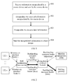
- a relay method of a transport bearer includes: receiving information encapsulated by a source device and sent by the source device; decapsulating the information encapsulated by the source device; encapsulating the decapsulated information; and sending the encapsulated information to a host device.
- the specific process may be as follows:
- the received information may be information of an uplink or may be information of a downlink, that is, the source device may be a self-backhauling base station, and correspondingly, the host device may be a gateway; or the source device may be a gateway, and correspondingly, the host device may be a self-backhauling base station; additionally, the information may be a signaling message, or may be data, and specifically may be as follows:
- Receiving information encapsulated by a gateway and sent by the gateway for example:
- a signaling message encapsulated by the gateway and sent by the gateway may carry a self-backhauling base station identity, so that subsequently a relay base station may encapsulate a parsed signaling message according to the self-backhauling base station identity, that is, the relay base station may find a corresponding self-backhauling base station according to the self-backhauling base station identity, thus obtaining relevant information such as a signaling bearer address of the self-backhauling base station, so that the relay base station may send the signaling message to the self-backhauling base station corresponding to the self-backhauling base station identity; additionally, a source address of the signaling message encapsulated by the gateway is a signaling bearer address of the gateway, and a destination address is a signaling bearer address of the relay base station; or receiving data encapsulated by the gateway and sent by the gateway, where a source address of the data encapsulated by the gateway
- Decapsulating the received information encapsulated by the self-backhauling base station for example:
- the relay base station may further select a gateway for the self-backhauling base station, so that subsequently signaling bearer address replacement may be performed on the parsed signaling message according to the selected gateway; and, an identity denoting that relay processing is performed, and/or a self-backhauling base station identity may be added to the decapsulated signaling message, so that the selected gateway may process the received information according to these added identities, that is, the identity denoting that the relay processing is performed and/or the self-backhauling base station identity.
- Decapsulating the received information encapsulated by the gateway for example:
- the source address of the decapsulated information is changed to an address of the relay base station, and the destination address is changed to an address of the gateway; for example:
- a source address of the decapsulated signaling message is changed to a signaling bearer address of the relay base station, and a destination address is changed to a signaling bearer address of the gateway; or a source address of the decapsulated data is changed to a data bearer address of the relay base station, and a destination address is changed to a data bearer address of the gateway.
- the source address of the decapsulated information is changed to an address of the relay base station, and the destination address is changed to an address of the self-backhauling base station; for example:
- a source address of the decapsulated signaling message is changed to a signaling bearer address of the relay base station, and a destination address is changed to a signaling bearer address of the self-backhauling base station; if in step 101, the signaling message sent by the gateway to the relay base station carries a self-backhauling base station identity, in this case, the parsed signaling message may be encapsulated according to the self-backhauling base station identity, that is, a corresponding self-backhauling base station is found according to the self-backhauling base station identity, thus obtaining relevant information such as a signaling bearer address of the self-backhauling base station; or a source address of the decapsulated data is changed to a data bearer address of the relay base station, and a destination address is changed to a data bearer address of the self-backhauling base station.
- the decapsulated information may be encapsulated according to the address mapping table, that is, replacement address items corresponding to the source address and the destination address that are in the received information may be determined by querying the address mapping table, for example, it is known by querying the address mapping table that, a replacement address corresponding to an source address is an address A of the relay base station, and therefore the source address is changed to the address A of the relay base station, and it is known by querying the address mapping table that, a replacement address corresponding to an destination address is an address B of the gateway, and therefore the destination address is changed to the address B of the gateway.
- signaling identity replacement may be further performed on the parsed signaling message, or data tunnel identity replacement may be performed on the parsed data.
- the information whose source address and destination address are changed is sent to the gateway;
- the information whose source address and destination address are changed is sent to the self-backhauling base station.
- the relay base station may further set up another mapping table according to content of the exchanged information, that is, content of the decapsulated information, for example, set up a signaling identity pair mapping table or tunnel mapping table, so that during subsequent transport, the decapsulated information may be encapsulated according to these mapping tables, for example, signaling identity replacement is performed on the parsed signaling message according to the signaling identity pair mapping table, or tunnel identity replacement is performed on the parsed data according to the tunnel mapping table; additionally, when the received information sent by the self-backhauling base station is a signaling message, after the signaling message is parsed, content of the signaling message may be further added to stored context information of the self-backhauling base station, that is, the content of the signaling message is reserved as one of contents of the context information of the self-backhauling base station.
- content of the signaling message may be further added to stored context information of the gateway, that is, the content of the signaling message is reserved as one of contents of the context information of the gateway corresponding to the self-backhauling base station.
- the relay base station when receiving the information encapsulated by the source device and sent by the source device, the relay base station first decapsulates the information, encapsulates the information again, and then sends the encapsulated information to the host device, so that the relay function of the relay base station is achieved, and meanwhile it is ensured that the information has only a layer of encapsulation in the transport procedure, so as to avoid a case that a high overhead caused by two layers of encapsulation occurs in the transport procedure, and compared with the prior art, the overhead in the transport procedure may be reduced, and the transport efficiency may be increased. Furthermore, because processing of a node (the gateway of the relay base station) is reduced in the transport procedure, a time delay may be reduced.
- a long term evolution (LTE, Long Term Evolution) system is taken as an example to further perform illustration in detail.
- LTE Long Term Evolution
- FIG. 2 for a schematic diagram of the LTE system, where a long term evolved NodeB (eNB, E-UTRAN Node B, abbreviated as an evolved NodeB below) is a relay base station, a mobility management entity (MME, Mobility Management Entity) is a gateway corresponding to signaling message transport, and a serving gateway (S-GW, Serving-Gateway) is a gateway corresponding to data transport.
- MME Mobility Management Entity
- S-GW Serving-Gateway
- a UE User Equipment, abbreviated as a UE
- a relay function of a transport bearer needs to be added to the evolved NodeB, and may be abbreviated as an "S l Relay" function, and the function includes:
- the evolved NodeB provides a relay function for a signaling interface between the self-backhauling base station and the MME, and the evolved NodeB sets up two segments of transport bearers between the evolved NodeB and the self-backhauling base station, and between the evolved NodeB and the MME, that is, two segments of backhauling transport bearers of a signaling message in FIG. 2 , so as to ensure normal signaling message interaction between the self-backhauling base station and the MME; the evolved NodeB provides a relay function for data transport between the self-backhauling base station and the S-GW, and the evolved NodeB sets up two segments of transport bearers (that is, two segments of backhauling transport bearers of data in FIG.
- the information transferred in the transport bearer may be a signaling message, and may also be data, and therefore, for better description, the following several embodiments are respectively illustrated by taking signaling information and data as an example.
- interaction of setting up a signaling message "S1 Setup" of an S1 interface (setting up an S1 interface) in the LTE system is taken as an example for illustration.
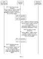
- Signaling message interaction includes both an uplink direction and a downlink direction, where processing in both the uplink direction and the downlink direction may be independently performed; referring to FIG. 3 , the specific process may be as follows:
- A201 The self-backhauling base station encapsulates content of a signaling message S1 Setup request message, where a destination address is filled with an address of the evolved NodeB, and a source address is its own address (that is, an address of the self-backhauling base station), and then sends the encapsulated signaling message to the evolved NodeB;
- the evolved NodeB After receiving the signaling message S1 Setup request message, the evolved NodeB decapsulates the signaling message S1 Setup request message, and parses that the destination address of the received signaling message S1 Setup request message is an address of the evolved NodeB, and the source address is the address of the self-backhauling base station;
- the evolved NodeB may parse the signaling message S1 Setup request message, and reserve content of the signaling message S1 Setup request message as one of contents of context information of the self-backhauling base station.
- A203 Encapsulate the decapsulated signaling message S1 Setup request message, change the destination address of the signaling message S1 Setup request message to an address of the MME, and change the source address to its own address, that is, an address of the evolved NodeB;
- the evolved NodeB may further select a proper MME for the self-backhauling base station, and make a record, for convenience of subsequent signaling message interaction;
- the evolved NodeB may further add an identity denoting that relay processing is performed, and/or add a self-backhauling base station identity to the content of the signaling message provided for the MME, so that the MME may process the received signaling message according to the identity denoting that the relay processing is performed and the self-backhauling base station identity, where the self-backhauling base station identity may be an Internet protocol (IP, Internet Protocol) address of the self-backhauling base station, or an equipment identity (ID, IDentity) of the self-backhauling base station or an equipment name (name) of the self-backhauling base station.
- IP Internet protocol
- ID equipment identity
- name equipment name
- A204 The eNB sends the encapsulated signaling message S1 Setup request message to the MME, so that the MME processes the signaling message.
- the MME encapsulates content of a signaling message S1 Setup response message, where a destination address is filled with an address of the evolved NodeB, and a source address is its own address (that is, an address of the MME), and then sends the encapsulated signaling message S1 Setup response message;
- the MME may carry the self-backhauling base station identity in the signaling message S1 Setup response message, for example, an IP address, an equipment ID, an equipment name, so that the evolved NodeB may know which self-backhauling base station is a receiver of the signaling message, that is, after receiving the signaling message, the evolved NodeB may send the re-encapsulated signaling message to the self-backhauling base station corresponding to the self-backhauling base station identity;
- S1 Setup response message for example, an IP address, an equipment ID, an equipment name
- the evolved NodeB After receiving the signaling message S1 Setup response message, the evolved NodeB decapsulates the signaling message S1 Setup response message, and parses that the destination address of the signaling message S1 Setup is the address of the evolved NodeB, and the source address is the address of the MME;
- the evolved NodeB may further parse the signaling message, and reserve content of the signaling message as one of contents of the context information of the MME corresponding to the self-backhauling base station;
- the evolved NodeB encapsulates the decapsulated signaling message S1 Setup response message, changes the destination address to an address of the self-backhauling base station, and changes the source address to its own address, that is, an address of the evolved NodeB;
- the evolved NodeB sends the encapsulated signaling message S1 Setup response message to the self-backhauling base station, so that the self-backhauling base station processes the signaling message S1 Setup response message.
- the relay base station may further set up a mapping table according to content of the exchanged signaling message, that is, content of the decapsulated signaling message, for example, set up a signaling identity pair mapping table, so that during subsequent transport, the decapsulated signaling message may be encapsulated according to the mapping table.
- an address in the foregoing process mainly refers to a bearer address used to transport a signaling message, that is, a signaling address.
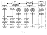
- the IP protocol is taken as an example in the drawing, a source address and a destination address of a transmission protocol bearer address between the self-backhauling base station and the evolved NodeB are denoted with diagonal shade, and a source address and a destination address of a transmission protocol bearer address between the evolved NodeB and the MME are denoted with mesh shade, where the non access stratum (NAS, Non-Access-Stratum), the stream control transmission protocol (SCTP, Stream Control Transmission Protocol), the radio resource control (RRC, Radio Resource Control), the packet data convergence protocol (PDCP, Packet Data Convergence Protocol), the radio link control layer (RLC, Radio Link Control), the media access control layer (MAC, Media Access Control), the physical layer (PHY, Physical Layer), the layer 2 (L2, Layer 2) and the layer 1 (L1, Layer 1) are protocols of other layers; because modification of these protocol layer solutions is not involved in solutions according to the embodiments of the present invention, and is
- the source address and the destination address of the transmission protocol bearer address between the self-backhauling base station and the evolved NodeB, and the source address and the destination address of the transmission protocol bearer address between the evolved NodeB and the MME are different, but, only a layer of a protocol header may be ensured, thus avoiding a case of two layers of encapsulation in the prior art, and compared with the prior art, the overhead in the signaling message transport procedure may be greatly reduced, and the transport efficiency may be increased. Furthermore, because processing of a node (the gateway of the relay base station) is reduced in the transport procedure, a time delay may be reduced.
- interaction of a signaling message "S1 Setup" is taken as an example for description; because the interaction of this signaling message is unrelated to a UE, so in order to better illustrate the embodiment of the present invention, in this embodiment, signaling message interaction related to a UE is taken as an example for detailed description below.
- this pair of signaling identities is named as an eNB UE S1AP ID and an MME UE S1AP ID, and for convenience of description, in the following embodiment, different subscripts are added to the signaling identities according to difference between devices generating this pair of signaling identities. For example, if this pair of signaling identities is generated by an eNB, this pair of signaling identities is named as an eNB UE S1AP ID eNB and an MME UE S1AP ID eNB . It should be noted that, for convenience of description, in this embodiment, a subscript of a signaling identity generated by a self-backhauling base station is denoted with "X", for example, an eNB UE S1AP ID X .
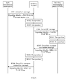
- the signaling message interaction process includes both an uplink direction and a downlink direction, where processing processes in both the uplink direction and the downlink direction may be independently performed; referring to FIG. 5 , the specific processes may be as follows:
- the self-backhauling base station After receiving the signaling message DOWNLINK NAS TRANSPORT carrying the signaling identity MME UE S1AP ID eNB , the self-backhauling base station parses the signaling message, and records the sent signaling identity MME UE S1AP ID eNB;
- the evolved NodeB may set up a corresponding signaling identity pair mapping table according to the content of the signaling message exchanged between the self-backhauling base station and the MME, so that in subsequent signaling message interaction, the evolved NodeB may encapsulate the received signaling message according to the mapping table; referring to table 1, the signaling identity pair mapping table may specifically be as follows; Table 1 Signaling identity pair mapping table set up by the evolved NodeB Received Replaced with eNB UE S1AP ID X eNB UE S1AP ID eNB MME UE S IAP ID eNB MME UE UE S1AP ID MME eNB UE S1AP ID eNB eNB UE S1 AP ID X MME UE S1AP ID MME MME UE S1AP ID eNB
- the UE is identified through this pair of signaling identities, namely, the eNB UE S1AP ID X and the MME UE S1AP ID eNB , between the self-backhauling base station and the evolved NodeB, while the UE is identified through this pair of signaling identities, namely, the eNB UE S1AP ID eNB and the MME UE S1AP ID MME , between the evolved NodeB and the MME.
- a mapping relation between these two pairs of signaling identity pairs (referring to table 1) is completed by the evolved NodeB, and in this way, the evolved NodeB completes the relay of two segments of signaling message bearers.
- the relay base station when receiving the signaling message encapsulated by the source device and sent by the source device, the relay base station first decapsulates the signaling message, encapsulates the signaling message again, and then sends the encapsulated signaling message to the host device, thus achieving the relay function of the relay base station, and ensuring that the signaling message has only a layer of encapsulation in the transport procedure, so as to avoid a case that a high overhead caused by two layers of encapsulation occurs in the transport procedure, and compared with the prior art, the overhead in the transport procedure may be reduced, and the transport efficiency may be increased. Furthermore, because processing of a node (the gateway of the relay base station) is reduced in the transport procedure, a time delay may be reduced.
- data transport in a GTP tunnel in an LTE system is taken as an example for illustration.
- a data transport bearer set up as a GTP tunnel is taken as an example for illustration, and specifically the setup may be performed through a signaling message Initial Context Setup or E-RAB Setup of a transport bearer involved in the LTE system; as shown in FIG. 6 , a brief process about setting up a GTP tunnel may be as follows:
- An MME generates a tunnel endpoint GTP-TEID MME , and selects an "S-GW address" as a transport bearer address of a gateway, and send the GTP-TEID MME and the S-GW address to an evolved NodeB through a request message about setting up a transport bearer.
- A402 The evolved NodeB parses the request message about setting up a transport bearer, generates a tunnel endpoint GTP-TEID uplink , and replaces the tunnel endpoint GTP-TEID MME in the original request message with the newly-generated tunnel endpoint GTP-TEID uplink, and meanwhile, replaces the transport bearer address: "an address of an S-GW" with "a data plane address of the evolved NodeB", and then sends the GTP-TEID uplink and the data plane address of the evolved NodeB to a self-backhauling base station through the request message about setting up a transport bearer;
- the self-backhauling base station generates a tunnel endpoint GTP-TEID X , selects "a data plane address of the self-backhauling base station" as a transport bearer address, and send the GTP-TEID X and the data plane address of the self-backhauling base station to the evolved NodeB through a response message about setting up a transport bearer;
- the evolved NodeB parses the received response message about setting up a transport bearer, generates a tunnel endpoint GTP-TEID downlink , replaces the tunnel endpoint GTP-TEID X in the original signaling message with the newly-generated tunnel endpoint GTP-TEID downlink , and meanwhile, replaces the transport bearer address: "the data plane address of the self-backhauling base station" with "the data plane address of the evolved NodeB", and sends the GTP-TEID downlink and the data plane address of the evolved NodeB to the MME through the response message about setting up a transport bearer;
- the evolved NodeB may set up a tunnel mapping table, which may specifically refer to table 2; Table 2 Tunnel mapping table set up by an eNB Received Sending Destination transport bearer address GTP-TEID downlink GTP-TEID X Data plane address of a self-backhauling base station GTP-TEID uplink GTP- TEID MME S-GW data plane address
- a GTP tunnel may further be set up by adopting other methods, that is, the foregoing process pays attention to implementing the content of the signaling message instead of paying attention to how to implement the transport of the signaling message.
- the signaling message is used for implementing the setup of a data transport bearer, so an address involved in the signaling content is mainly directed to an address used to transport data, that is, a data plane address; meanwhile, the foregoing address takes an IP address as an example, and is not limited to an IPv4 address or IPv6 address.
- the S-GW encapsulates data, and specifically downlink data may be encapsulated in a GTP tunnel whose destination tunnel endpoint is the GTP-TEID downlink , the destination address is the evolved NodeB, the source address is the S-GW, and then the downlink data is transferred to the evolved NodeB through the GTP tunnel;
- the evolved NodeB After receiving the encapsulated downlink data, the evolved NodeB decapsulates the downlink data encapsulated in the GTP tunnel of the GTP-TEID downlink ;
- the evolved NodeB re-encapsulates the decapsulated downlink data according to a tunnel mapping relation, and specifically the decapsulated downlink data may be encapsulated in a GTP tunnel whose destination tunnel endpoint is the GTP-TEID X , the destination address is the self-backhauling base station, and the source address is the evolved NodeB;
- C404 The evolved NodeB transfers the encapsulated downlink data to the self-backhauling base station through the GTP tunnel;
- the self-backhauling base station After receiving the encapsulated downlink data, the self-backhauling base station parses the downlink data encapsulated in the GTP tunnel of the GTP-TEID X , and sends the parsed data to the UE through an air interface according to a downlink air interface RAB corresponding to the GTP-TEID X
- the UE sends uplink data to the self-backhauling base station through an air interface radio access bearer (RAB, Radio Access Bearer);
- RAB Radio Access Bearer
- the self-backhauling base station encapsulates, according to the GTP-TEID uplink tunnel corresponding to the uplink air interface RAB, the received uplink data in a GTP tunnel whose destination tunnel endpoint is the GTP-TEID uplink , the destination address is the eNB, and the source address is the self-backhauling base station;
- the evolved NodeB After receiving the encapsulated uplink data, the evolved NodeB decapsulates the uplink data encapsulated in the GTP tunnel of the GTP-TEID uplink ;
- the evolved NodeB re-encapsulates the decapsulated uplink data according to a tunnel mapping relation, and specifically the parsed uplink data may be re-encapsulated in a GTP tunnel whose destination endpoint is the GTP-TEID MME , the destination address is the S-GW, and the source address is the evolved NodeB;
- D404 The evolved NodeB transfers the encapsulated uplink data to the S-GW through the GTP tunnel;
- the S-GW After receiving the encapsulated uplink data, the S-GW parses the uplink data encapsulated in the GTP tunnel of the GTP-TEID MME, and sends the parsed uplink data to a node at a next level.
- an address in the foregoing process mainly refers to an address used to transport data, that is, a data plane address.
- the foregoing address takes an IP address as an example, and is not limited to an IPv4 address or IPv6 address.
- FIG. 8 for a protocol stack corresponding to the foregoing method, the GTP, the user datagram protocol (UDP, User Datagram Protocol) and the IP protocol are taken as an example in the drawing, a transmission protocol between the self-backhauling base station and the evolved NodeB is denoted with diagonal shade, and a transmission protocol between the evolved NodeB and the S-GW is denoted with mesh shade, where the PDCP, the RLC, the MAC, the PHY, the L2 and the L1 are protocols of other layers, because modification of these protocol layer solutions is not involved in solutions according to the embodiments of the present invention, and is not described in detail here; additionally, it should be noted that for simplicity and convenience of drawing, protocols in the drawing are all denoted with English abbreviation.
- the GTP tunnel between the self-backhauling base station and the evolved NodeB is different from the GTP tunnel between the evolved NodeB and the MME; for example, the TEID of GTP tunnel, and the source address and the destination address of the IP address are different.
- the relay base station when receiving the data encapsulated by the source device and sent by the source device, the relay base station, that is, the evolved NodeB first decapsulates the data, encapsulates the data again, and then sends the encapsulated data to the host device, thus achieving the relay function of the relay base station, and ensuring that the data has only a layer of encapsulation in the transport procedure, so as to avoid a case that a high overhead caused by two layers of encapsulation occurs in the transport procedure, and compared with the prior art, the overhead in the transport procedure may be reduced, and the transport efficiency may be increased. Furthermore, because processing of a node (the gateway of the relay base station) is reduced in the transport procedure, a time delay may be reduced.
- the self-backhauling base station may be handed over between different relay base stations (in this embodiment, the relay base station takes an evolved NodeB as an example), and therefore, in this embodiment, a case that the self-backhauling base station is handed over between different evolved NodeBs is illustrated (in this embodiment, a transport bearer being a GTP tunnel is further taken as an example for illustration).
- the self-backhauling base station performs relay through the source evolved NodeB, and interacts with an S-GW.
- the source evolved NodeB specifically maintains a segment 1 GTP tunnel and a segment 2 GTP tunnel, and sets up a mapping relation, that is, sets up a tunnel mapping table between the self-backhauling base station and the gateway;
- the self-backhauling base station performs relay through the destination evolved NodeB and the source evolved NodeB, and interacts with the S-GW.
- the destination evolved NodeB specifically maintains a segment 4 GTP tunnel and a segment 3 GTP tunnel, and sets up a mapping relation, that is, sets up a tunnel mapping table between the self-backhauling base station and the source relay base station;
- the source evolved NodeB specifically maintains the segment 3 GTP tunnel and the segment 2 GTP tunnel, and sets up a mapping relation, that is, sets up a tunnel mapping table between the destination relay base station and the gateway;
- the destination relay base station may be equivalent to the self-backhauling base station;
- the self-backhauling base station After handover, the self-backhauling base station performs relay through the destination evolved NodeB, and interacts with the S-GW.
- the destination evolved NodeB specifically maintains the segment 4 GTP tunnel and a segment 5 GTP tunnel, and sets up a mapping relation, that is, sets up a tunnel mapping table between the self-backhauling base station and the gateway.
- uplink and downlink tunnels are not distinguished for the foregoing tunnels 1, 2, 3, 4 and 5; during specific implementation, the uplink tunnel and the downlink tunnel separately perform processing according to methods described in previous embodiments, which is not repeatedly described here.
- the relay of the transport bearer of the data "before handover” and “after handover” is the same as that in the fourth embodiment, and the relay of the transport bearer of signaling also only involves stages of "before handover” and "after handover”, and is similar to those in the second embodiment and the third embodiment, so the relay is not repeatedly described here; for convenience of description, in this embodiment, only the case of "in handover" is illustrated.
- the source relay base station may send, to the destination relay base station, a handover request about handover from the source relay base station to the destination relay base station, where the handover request carries an address of the source relay base station and a gateway address; after receiving the handover request, the destination relay base station returns a response message to the source relay base station, and when the source relay base station receives the response message denoting consent, where the response message denoting consent is returned by the destination relay base station and carries the address of the destination relay base station, and after the information encapsulated by the gateway is parsed, the source address of the parsed information is changed to the address of the source relay base station, the destination address is changed to the address of the destination relay base station, and then the changed information is sent to the destination relay base station, so that the destination relay base station relays the changed information to the self-backhauling base station.
- the following takes an example for illustration.
- the process may be as follows:
- the source evolved NodeB initiates a handover request to the destination evolved NodeB, and meanwhile may carry a transport bearer setup request, where the handover request includes a tunnel endpoint identity (TEID) generated by the source evolved NodeB and/or the data plane address of the source evolved NodeB.
- TEID tunnel endpoint identity
- the handover request may further be indirectly sent to the destination evolved NodeB, and for example, the source evolved NodeB sends the handover request to the MME, and then the MME sends the handover request to the destination evolved NodeB;
- the destination evolved NodeB initiates a handover response to the source evolved NodeB.
- the handover response refers to a handover response denoting success (or consent to handover)
- a transport bearer setup request is further carried simultaneously, in this case, a transport bearer setup response may be further carried, and the handover response includes the tunnel endpoint identity (TEID) generated by the destination evolved NodeB and/or the data plane address of the destination evolved NodeB;
- TEID tunnel endpoint identity
- the handover response may further be indirectly sent to the source evolved NodeB, and for example, the destination evolved NodeB sends the handover request to the MME, and then the MME sends the handover request to the source evolved NodeB;
- the setup of the GTP tunnel 3 is completed, and the source evolved NodeB updates the tunnel mapping table, 2->1 is updated as 2->3, the destination transport bearer address is updated as the data plane address of the destination evolved NodeB; 1->2 is updated as 3->2, and the destination transport bearer address is invariable, and is the data plane address of the S-GW.
- Table 4 GTP tunnel Destination transport bearer address 2->3 Data plane address of a destination evolved NodeB 3->2 Data plane address of an S-GW
- the self-backhauling base station accesses the destination evolved NodeB, and adopts a method similar to that in steps 501 and 502, and the self-backhauling base station and the destination evolved NodeB negotiate the setup of the GTP tunnel 4; the destination evolved NodeB newly sets up a mapping relation in the tunnel mapping table, referring to table 5; Table 5 GTP tunnel Destination transport bearer address 3->4 Data plane address of a self-backhauling base station 4->3 Data plane address of a source evolved NodeB
- the destination evolved NodeB adopts the same method to set up the tunnel 5 between the destination evolved NodeB and the gateway;
- data transport and relay processing may be performed on the source evolved NodeB and the destination evolved NodeB respectively.
- the destination evolved NodeB parses the data encapsulated by the self-backhauling base station, then encapsulates the parsed data according to the tunnel mapping table, and then sends the data to the source evolved NodeB
- the source evolved NodeB after parsing the data encapsulated by the destination evolved NodeB, the source evolved NodeB then encapsulates the parsed data according to its own tunnel mapping table, and then sends the data to the gateway; similarly, after receiving the data encapsulated by the gateway, the source evolved NodeB parses the data encapsulated by gateway, encapsulates the parsed data according to the tunnel mapping table stored by itself, and then sends the data to the destination evolved NodeB, and the destination evolved NodeB parses the data,
- a specific protocol stack corresponding to the process may be as shown in FIG. 11 , and the GTP, the UDP and the IP protocol are taken as an example in the drawing, the transmission protocol between the self-backhauling base station and the destination evolved NodeB is denoted with diagonal shade, the transmission protocol between the destination evolved NodeB and the source evolved NodeB is denoted with vertical line shade, and the transmission protocol between the source evolved NodeB and the S-GW is denoted with mesh shade, where the PDCP, the RLC, the MAC, the PHY, the L2 and the L1 are protocols of other layers, because modification of these protocol layer solutions is not involved in solutions according to the embodiments of the present invention, and is not described in detail here; additionally, it should be noted that for simplicity and convenience of drawing, protocols in the drawing are all denoted with English abbreviation.
- the relay base station when receiving the data encapsulated by the source device and sent by the source device, the relay base station first decapsulates the data, encapsulates the data again, and then sends the encapsulated data to the host device, thus achieving the relay function of the relay base station, and ensuring that the data has only a layer of encapsulation in the transport procedure, so as to avoid a case that a high overhead caused by two layers of encapsulation occurs in the transport procedure, and compared with the prior art, the overhead in the transport procedure may be reduced, and the transport efficiency may be increased. Furthermore, because processing of a node (the gateway of the relay base station) is reduced in the transport procedure, a time delay may be reduced. Further, if in the transport procedure, the relay base station is handed over because the self-backhauling base station moves, the relay function provided by the relay base station may be further utilized to implement seamless handover of the relay base station, thus ensuring accuracy of data transfer.
- an embodiment of the present invention further correspondingly provides a relay base station, and as shown in FIG. 12 , the relay base station includes a receiving unit 601, a decapsulating unit 602, an encapsulating unit 603 and a sending unit 604.
- the receiving unit 601 is configured to receive information encapsulated by a source device and sent by the source device, where the source device may be a self-backhauling base station, and, a host device may be a gateway; or the source device is a gateway, and the host device is a self-backhauling base station; additionally, the information mentioned there may be a signaling message or data.
- the decapsulating unit 602 is configured to decapsulate the information encapsulated by the source device and received by the receiving unit 601.
- the encapsulating unit 603 is configured to encapsulate the information decapsulated by the decapsulating unit 602.
- the sending unit 604 is configured to send the information encapsulated by the encapsulating unit 603 to the host device.
- the receiving unit 601 may include a signaling receiving subunit and a data receiving subunit.
- the signaling receiving subunit is configured to receive a signaling message encapsulated by a source device and sent by the source device.
- the data receiving subunit is configured to receive data encapsulated by a source device and sent by the source device.
- the decapsulating unit 602 may include a signaling decapsulating subunit and a data decapsulating subunit.
- the signaling decapsulating subunit is configured to parse the signaling message encapsulated by the source device and received by the signaling receiving subunit.
- the data decapsulating subunit is configured to parsed the data encapsulated by the source device and received by the data receiving subunit.
- the encapsulating unit 603 may include a signaling encapsulating subunit and a data encapsulating subunit.
- the signaling encapsulating subunit is configured to perform address replacement on the signaling message parsed by the signaling decapsulating subunit.
- the data encapsulating subunit is configured to perform address replacement on the data parsed by the data decapsulating subunit.
- the sending unit 604 may include a signaling sending subunit and a data sending subunit.
- the signaling sending subunit is configured to send the signaling message replaced by the signaling encapsulating subunit to the host device.
- the data sending subunit is configured to send the data replaced by the data encapsulating subunit to the host device.
- the relay base station may further include a selecting unit 605.
- the selecting unit 605 is configured to select a gateway for a self-backhauling base station.
- the signaling encapsulating subunit is configured to perform, according to the gateway selected by the selecting unit 605, address replacement on the signaling message decapsulated by the signaling decapsulating subunit.
- the relay base station may further include a signaling identity processing unit 606.
- the signaling identity processing unit 606 is configured to perform signaling identity replacement on the signaling message parsed by the signaling decapsulating subunit.
- the signaling identity processing unit 606 may include a signaling mapping table setup subunit and a signaling identity replacement subunit.
- the signaling mapping table setup subunit is configured to set up a signaling identity pair mapping table.
- the signaling identity replacement subunit is configured to perform signaling identity replacement on the parsed signaling message according to the signaling identity pair mapping table set up by the signaling mapping table setup subunit.
- the relay base station may further include an identity adding unit 607.
- the identity adding unit 607 is configured to add an identity denoting that relay processing is performed, and/or add a self-backhauling base station identity to the signaling message parsed by the signaling decapsulating subunit, so that the gateway processes the received information according to the identity denoting that the relay processing is performed and/or the self-backhauling base station identity.
- the relay base station may further include a context adding unit 608.
- the context adding unit 608 is configured to add content of the signaling message parsed by the signaling decapsulating subunit to stored context information of the self-backhauling base station or gateway.
- the relay base station may further include a tunnel identity processing unit 609.
- the tunnel identity processing unit 609 is configured to perform data tunnel identity replacement on the data parsed by the data decapsulating subunit.
- the tunnel identity processing unit 609 may include a data mapping table setup subunit and a tunnel identity replacement subunit.
- the data mapping table setup subunit is configured to set up a tunnel mapping table.
- the self-backhauling base station may be handed over between different relay base stations, in this case, if it is in handover, with respect to the source relay base station, the destination relay base station is equivalent to a self-backhauling base station, and a mapping table set up by the source relay base station is a tunnel mapping table between the destination relay base station and a gateway; while with respect to the destination relay base station, the source relay base station is equivalent to a gateway, a tunnel mapping table set up by the destination relay base station is a tunnel mapping table between the self-backhauling base station and the source relay base station; if it is after handover, a tunnel mapping table set up by the destination relay base station is a tunnel mapping table between the self backhauling base station and a gateway.
- the tunnel identity replacement subunit is configured to perform tunnel identity replacement on the parsed data according to the tunnel mapping table set up by the data mapping table setup subunit.
- the relay base station in this embodiment adopts the following steps: when the receiving unit 601 receives information encapsulated by the source device and sent by the source device, the decapsulating unit 602 first decapsulates the information, then the encapsulating unit 603 encapsulates the information again, and then the sending unit 604 sends the information to the host device, thus achieving the relay function of the relay base station, and ensuring that the information has only a layer of encapsulation in the transport procedure, so as to avoid a case that a high overhead caused by two layers of encapsulation occurs in the transport procedure, and compared with the prior art, the overhead in the transport procedure may be reduced, and the transport efficiency may be increased.
- a time delay may be reduced.
- the relay base station is handed over because the self-backhauling base station moves, the relay function provided by the relay base station may be further utilized to implement seamless handover of the relay base station, thus ensuring accuracy of data transfer.
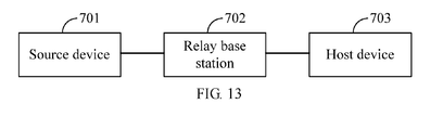
- an embodiment of the present invention further provides a communication system, and as shown in FIG. 13 , the communication system includes a source device 701, any relay base station 702 and host device 703 that are provided in the embodiments of the present invention.
- the source device 701 is configured to encapsulate information required to be sent to the host device 703 and send the encapsulated information to the relay base station 702, where the information mentioned here may be a signaling message or data.
- the relay base station 702 is configured to receive the information encapsulated by the source device 701 and sent by the source device 701, decapsulate the information encapsulated by the source device 701, encapsulate the decapsulated information, and send the encapsulated information to the host device 703.
- the host device 703 is configured to receive the encapsulated information sent by the relay base station 702.
- the relay base station may specifically be an evolved NodeB, and the source device 701 may specifically be a self-backhauling base station; correspondingly, the host device 703 specifically is a gateway, such as an MME or an S-GW; or, the source device 701 specifically is a gateway, such as an MME or an S-GW, and correspondingly, the host device 703 specifically is a self-backhauling base station.
- the relay base station 702 is further configured to select a gateway for a self-backhauling base station.
- the self-backhauling base station may be handed over between different relay base stations 702; therefore, when the relay base station 702 is used as a source relay base station, the relay base station 702 is further configured to send, to the destination relay base station, a handover request of handing over from the relay base station 702 to a destination relay base station, where the handover request carries an address of the source relay base station and a gateway address; and receive a response message denoting consent, where the response message denoting consent is returned by the destination relay base station and carries an address of the destination relay base station, and encapsulates the information decapsulated by the gateway, change the source address of the decapsulated information to an address of the relay base station 702, change the destination address to an address of the destination relay base station, and then send the changed information to the destination relay base station, so that the destination relay base station relays the changed information to the self-backhauling base station.
- the relay base station 702 is further configured to receive a handover request of handing over from the source relay base station to the relay base station 702, where the handover request is sent by the source relay base station, and the handover request carries an address of the source relay base station and a gateway address; and return a response message denoting consent, where the response message denoting consent carries an address of the relay base station 702, to the source relay base station, and decapsulate the information encapsulated by the self-backhauling base station, change the source address of the decapsulated information to an address of the relay base station 702, change the destination address to an address of the source relay base station, and then send the changed information to the source relay base station, so that the source relay base station relays the changed information to the gateway.
- the fifth embodiment for details.
- the relay base station 702 when receiving the data encapsulated by the source device 701 and sent by the source device 701, the relay base station 702 first decapsulates the data, encapsulates the data again, and then sends the encapsulated data to the host device 703, thus achieving the relay function of the relay base station 702, and ensuring that the data has only a layer of encapsulation in the transport procedure, so as to avoid a case that a high overhead caused by two layers of encapsulation occurs in the transport procedure, and compared with the prior art, the overhead in the transport procedure may be reduced, and the transport efficiency may be increased.
- the gateway of the relay base station 702 because processing of a node (the gateway of the relay base station 702) is reduced in the transport procedure, a time delay may be reduced. Further, if in the transport procedure, the relay base station 702 is handed over because the self-backhauling base station moves, the relay function provided by the relay base station may be further utilized to implement seamless handover of the relay base station, thus ensuring accuracy of data transfer.
- the program may be stored in a computer readable storage medium.
- the storage medium may be a read-only memory (ROM, Read Only Memory), a random access memory (RAM, Random Access Memory), a magnetic disk or an optical disk.
Landscapes
- Engineering & Computer Science (AREA)
- Computer Networks & Wireless Communication (AREA)
- Signal Processing (AREA)
- Mobile Radio Communication Systems (AREA)
Applications Claiming Priority (2)
| Application Number | Priority Date | Filing Date | Title |
|---|---|---|---|
| CN200910163687XA CN101998679B (zh) | 2009-08-13 | 2009-08-13 | 一种传输承载的中继方法、装置和通信系统 |
| PCT/CN2010/075665 WO2011018002A1 (fr) | 2009-08-13 | 2010-08-03 | Procédé de relais, appareil de relais et système de communication de support de transport |
Publications (3)
| Publication Number | Publication Date |
|---|---|
| EP2458932A1 true EP2458932A1 (fr) | 2012-05-30 |
| EP2458932A4 EP2458932A4 (fr) | 2012-08-08 |
| EP2458932B1 EP2458932B1 (fr) | 2018-01-03 |
Family
ID=43585940
Family Applications (1)
| Application Number | Title | Priority Date | Filing Date |
|---|---|---|---|
| EP10807947.6A Not-in-force EP2458932B1 (fr) | 2009-08-13 | 2010-08-03 | Procédé de relais, appareil de relais et système de communication de support de transport |
Country Status (4)
| Country | Link |
|---|---|
| US (1) | US8792410B2 (fr) |
| EP (1) | EP2458932B1 (fr) |
| CN (1) | CN101998679B (fr) |
| WO (1) | WO2011018002A1 (fr) |
Cited By (1)
| Publication number | Priority date | Publication date | Assignee | Title |
|---|---|---|---|---|
| US11832097B2 (en) | 2013-12-13 | 2023-11-28 | M87, Inc. | Methods and systems and secure connections for joining wireless networks |
Families Citing this family (21)
| Publication number | Priority date | Publication date | Assignee | Title |
|---|---|---|---|---|
| IL206455A (en) | 2010-01-28 | 2016-11-30 | Elta Systems Ltd | Cellular communication system with moving base stations and methods and useful devices in collaboration with the above |
| CN101854717A (zh) * | 2010-06-09 | 2010-10-06 | 中兴通讯股份有限公司 | 数据传输方法、用户设备及基站 |
| SG10201509651TA (en) | 2010-11-24 | 2015-12-30 | Elta Systems Ltd | Various routing architectures for dynamic multi-hop backhauling cellular network and various methods useful in conjunction therewith |
| SG190389A1 (en) | 2010-11-24 | 2013-06-28 | Elta Systems Ltd | Architecture and methods for traffic management by tunneling in moving hierarchical cellular networks |
| CN103067428B (zh) | 2011-10-21 | 2016-08-10 | 华为技术有限公司 | 基站、服务处理方法和云计算系统 |
| JP5761462B2 (ja) * | 2012-03-23 | 2015-08-12 | 日本電気株式会社 | 無線基地局、通信ノード、無線基地局の制御方法及び通信ノードの制御方法 |
| EP2865235B1 (fr) * | 2012-06-22 | 2019-09-04 | NEC Corporation | Système de communication mobile pour appels d'urgence |
| WO2014121478A1 (fr) * | 2013-02-07 | 2014-08-14 | 华为技术有限公司 | Procédé, appareil et dispositif de réseau d'acquisition de relation d'adjacence entre des noeuds de réseau |
| WO2015096008A1 (fr) * | 2013-12-23 | 2015-07-02 | Telefonaktiebolaget L M Ericsson (Publ) | Procédé et nœud de réseau pour router des paquets de liaison terrestre |
| KR102184767B1 (ko) * | 2014-04-01 | 2020-12-01 | 삼성전자주식회사 | 복수의 디바이스를 포함하는 네트워크의 통신 방법 및 장치 |
| CN104053130B (zh) * | 2014-06-30 | 2017-10-17 | 华为技术有限公司 | 一种中继网络的消息处理方法及装置 |
| CN105530706B (zh) * | 2014-10-23 | 2019-07-26 | 电信科学技术研究院 | 一种传输下行数据的方法和设备 |
| KR102342144B1 (ko) * | 2014-12-01 | 2021-12-22 | 삼성전자주식회사 | 통신 시스템에서 분리된 tcp 연결을 설정하는 방법 및 장치와 이를 위한 핸드 오버 지원 방법 및 장치 |
| CN105657865B (zh) * | 2015-04-30 | 2019-10-11 | 宇龙计算机通信科技(深圳)有限公司 | 一种数据中转传输方法、系统和具备中继功能的ue |
| CN108617008B (zh) * | 2016-12-05 | 2019-09-17 | 大唐移动通信设备有限公司 | 一种业务数据处理的方法和装置 |
| WO2018107504A1 (fr) * | 2016-12-17 | 2018-06-21 | 华为技术有限公司 | Procédé et appareil de transmission de données |
| CN108809490B (zh) * | 2017-05-04 | 2022-11-08 | 中兴通讯股份有限公司 | 信令消息传输方法及装置 |
| CN110351700B (zh) | 2018-04-05 | 2022-06-17 | 中兴通讯股份有限公司 | 一种自接入回传链路的中继转发方法及节点 |
| CN110475368B (zh) * | 2018-05-10 | 2022-12-20 | 中兴通讯股份有限公司 | 信息传输方法及装置 |
| CN118828786A (zh) | 2019-07-10 | 2024-10-22 | 北京三星通信技术研究有限公司 | 数据包路由的方法及设备、数据包传输的控制方法及设备 |
| US11239898B1 (en) * | 2019-11-19 | 2022-02-01 | T-Mobile Innovations Llc | Relaying data to multiple access points |
Family Cites Families (16)
| Publication number | Priority date | Publication date | Assignee | Title |
|---|---|---|---|---|
| AU771091B2 (en) * | 1998-06-19 | 2004-03-11 | Juniper Networks, Inc. | Device for performing IP forwarding and ATM switching |
| TW588524B (en) | 2002-01-23 | 2004-05-21 | Ind Tech Res Inst | System and method to apply multi-protocol label switching network in GPRS |
| US8555352B2 (en) * | 2003-06-20 | 2013-10-08 | Juniper Networks, Inc. | Controlling access nodes with network transport devices within wireless mobile networks |
| CA2555145A1 (fr) | 2004-02-06 | 2005-08-25 | Wyeth | Diagnostics et therapeutiques du cancer |
| CN100459566C (zh) * | 2004-05-10 | 2009-02-04 | 华为技术有限公司 | 进行网络地址转换的网络中隧道中继的实现方法 |
| CN100334860C (zh) * | 2004-11-01 | 2007-08-29 | 杭州华为三康技术有限公司 | 提高设备转发性能的报文交互方法 |
| JP4330520B2 (ja) * | 2004-12-08 | 2009-09-16 | 富士通株式会社 | 通信装置 |
| JP4038221B2 (ja) * | 2005-12-08 | 2008-01-23 | フリービット株式会社 | 中継装置及びクライアント機器とサーバとの接続方法 |
| WO2007123733A2 (fr) * | 2006-03-31 | 2007-11-01 | Qualcomm Incorporated | Répéteur à couche physique améliorée pour une exploitation dans des systèmes wimax |
| US8265003B2 (en) * | 2006-09-15 | 2012-09-11 | Nec Corporation | Packet distribution system and packet distribution method |
| US20080165776A1 (en) | 2007-01-08 | 2008-07-10 | Zhifeng Tao | Relay Tunneling in Wireless Multi-User Multi-Hop Relay Networks |
| US20080219203A1 (en) * | 2007-03-09 | 2008-09-11 | Industrial Technology Research Institute. | Method for mac process and flexible connection in wireless multi-hop relaying network |
| EP2172072A4 (fr) | 2007-07-13 | 2011-07-27 | Nortel Networks Ltd | Qualité de contrôle de service dans des environnements de communication sans fil à sauts multiples |
| KR20090052784A (ko) * | 2007-11-21 | 2009-05-26 | 엘지전자 주식회사 | 릴레이를 통한 통신 방법 |
| JP5373821B2 (ja) * | 2008-01-17 | 2013-12-18 | アルカテル−ルーセント | ワイヤレス中継ネットワークにおけるデータ中継伝送のための方法およびデバイス |
| CN101883295B (zh) * | 2009-05-06 | 2014-04-30 | 华为技术有限公司 | 业务传输处理方法、节点设备及网络系统 |
-
2009
- 2009-08-13 CN CN200910163687XA patent/CN101998679B/zh not_active Expired - Fee Related
-
2010
- 2010-08-03 WO PCT/CN2010/075665 patent/WO2011018002A1/fr not_active Ceased
- 2010-08-03 EP EP10807947.6A patent/EP2458932B1/fr not_active Not-in-force
-
2012
- 2012-02-10 US US13/370,732 patent/US8792410B2/en active Active
Cited By (2)
| Publication number | Priority date | Publication date | Assignee | Title |
|---|---|---|---|---|
| US11832097B2 (en) | 2013-12-13 | 2023-11-28 | M87, Inc. | Methods and systems and secure connections for joining wireless networks |
| US12238513B2 (en) | 2013-12-13 | 2025-02-25 | M87, Inc. | Methods and systems and secure connections for joining wireless networks |
Also Published As
| Publication number | Publication date |
|---|---|
| US20120140697A1 (en) | 2012-06-07 |
| CN101998679A (zh) | 2011-03-30 |
| US8792410B2 (en) | 2014-07-29 |
| EP2458932A4 (fr) | 2012-08-08 |
| WO2011018002A1 (fr) | 2011-02-17 |
| CN101998679B (zh) | 2012-11-07 |
| EP2458932B1 (fr) | 2018-01-03 |
Similar Documents
| Publication | Publication Date | Title |
|---|---|---|
| EP2458932B1 (fr) | Procédé de relais, appareil de relais et système de communication de support de transport | |
| US8797952B2 (en) | Self-backhauling in LTE | |
| EP2924940B1 (fr) | Procédés d'émission de données de plan d'utilisateur, élément de réseau de gestion de mobilité et noeud b évolué | |
| CN109005562B (zh) | 传输数据的方法、装置和系统 | |
| CN107005824B (zh) | 一种gtp-u下行报文的发送方法及装置 | |
| EP3920449A1 (fr) | Procédé et appareil de gestion d'identificateur | |
| US11405830B2 (en) | Information transmission method and apparatus | |
| US10939485B2 (en) | Mechanism for realizing LWA/LWIP aggregator function | |
| US20060262778A1 (en) | Unlicensed mobile access optimization | |
| CN102026398A (zh) | Lte中继系统中分组汇聚协议的实现方法和装置 | |
| JP2013520899A (ja) | ユーザ機器と3gpp発展型パケット・コアとの間でのマルチホーミング・サービス関連情報の転送 | |
| EP3229552B1 (fr) | Procédé et appareil pour configurer une connexion tcp déconnectée dans un système de communication | |
| CN102045802A (zh) | Sgw改变的切换过程中的数据发送方法、pgw及基站 | |
| CN114040343B (zh) | 一种wifi设备接入5g核心网方法及系统 | |
| JP2022549953A (ja) | データパケット送信方法および装置 | |
| CN103582010A (zh) | 一种实现融合网络数据传输方法、ue、接入网设备 | |
| US11317322B2 (en) | Data offloading method and gateway | |
| WO2010106653A1 (fr) | Station de base, dispositif de communication, procédé de relais et procédé de communication | |
| EP3454588B1 (fr) | Procédé et dispositif de transmission de messages | |
| CN115553054B (zh) | 用于通信的装置和方法 | |
| CN106792933B (zh) | 一种链路建立方法、基站、网关及系统 | |
| JP7806927B2 (ja) | 情報を設定する方法と装置及び通信システム | |
| EP3841833A1 (fr) | Technique de préparation de la mobilité d'un équipement d'utilisateur | |
| RU2780823C2 (ru) | Устройство и способ обработки беспроводной связи по транзитному соединению | |
| KR20240145862A (ko) | 이동 통신 시스템에서 세션 관리를 수행하는 방법 및 장치 |
Legal Events
| Date | Code | Title | Description |
|---|---|---|---|
| PUAI | Public reference made under article 153(3) epc to a published international application that has entered the european phase |
Free format text: ORIGINAL CODE: 0009012 |
|
| 17P | Request for examination filed |
Effective date: 20120220 |
|
| AK | Designated contracting states |
Kind code of ref document: A1 Designated state(s): AL AT BE BG CH CY CZ DE DK EE ES FI FR GB GR HR HU IE IS IT LI LT LU LV MC MK MT NL NO PL PT RO SE SI SK SM TR |
|
| A4 | Supplementary search report drawn up and despatched |
Effective date: 20120706 |
|
| RIC1 | Information provided on ipc code assigned before grant |
Ipc: H04W 88/04 20090101AFI20120702BHEP Ipc: H04W 28/06 20090101ALI20120702BHEP |
|
| DAX | Request for extension of the european patent (deleted) | ||
| 17Q | First examination report despatched |
Effective date: 20140314 |
|
| GRAP | Despatch of communication of intention to grant a patent |
Free format text: ORIGINAL CODE: EPIDOSNIGR1 |
|
| STAA | Information on the status of an ep patent application or granted ep patent |
Free format text: STATUS: GRANT OF PATENT IS INTENDED |
|
| INTG | Intention to grant announced |
Effective date: 20170203 |
|
| GRAS | Grant fee paid |
Free format text: ORIGINAL CODE: EPIDOSNIGR3 |
|
| GRAJ | Information related to disapproval of communication of intention to grant by the applicant or resumption of examination proceedings by the epo deleted |
Free format text: ORIGINAL CODE: EPIDOSDIGR1 |
|
| GRAL | Information related to payment of fee for publishing/printing deleted |
Free format text: ORIGINAL CODE: EPIDOSDIGR3 |
|
| STAA | Information on the status of an ep patent application or granted ep patent |
Free format text: STATUS: EXAMINATION IS IN PROGRESS |
|
| GRAP | Despatch of communication of intention to grant a patent |
Free format text: ORIGINAL CODE: EPIDOSNIGR1 |
|
| STAA | Information on the status of an ep patent application or granted ep patent |
Free format text: STATUS: GRANT OF PATENT IS INTENDED |
|
| INTC | Intention to grant announced (deleted) | ||
| INTG | Intention to grant announced |
Effective date: 20170713 |
|
| GRAA | (expected) grant |
Free format text: ORIGINAL CODE: 0009210 |
|
| STAA | Information on the status of an ep patent application or granted ep patent |
Free format text: STATUS: THE PATENT HAS BEEN GRANTED |
|
| AK | Designated contracting states |
Kind code of ref document: B1 Designated state(s): AL AT BE BG CH CY CZ DE DK EE ES FI FR GB GR HR HU IE IS IT LI LT LU LV MC MK MT NL NO PL PT RO SE SI SK SM TR |
|
| REG | Reference to a national code |
Ref country code: GB Ref legal event code: FG4D |
|
| REG | Reference to a national code |
Ref country code: CH Ref legal event code: EP Ref country code: AT Ref legal event code: REF Ref document number: 961370 Country of ref document: AT Kind code of ref document: T Effective date: 20180115 |
|
| REG | Reference to a national code |
Ref country code: IE Ref legal event code: FG4D |
|
| REG | Reference to a national code |
Ref country code: DE Ref legal event code: R096 Ref document number: 602010047830 Country of ref document: DE |
|
| REG | Reference to a national code |
Ref country code: NL Ref legal event code: MP Effective date: 20180103 |
|
| REG | Reference to a national code |
Ref country code: LT Ref legal event code: MG4D |
|
| REG | Reference to a national code |
Ref country code: AT Ref legal event code: MK05 Ref document number: 961370 Country of ref document: AT Kind code of ref document: T Effective date: 20180103 |
|
| PG25 | Lapsed in a contracting state [announced via postgrant information from national office to epo] |
Ref country code: NL Free format text: LAPSE BECAUSE OF FAILURE TO SUBMIT A TRANSLATION OF THE DESCRIPTION OR TO PAY THE FEE WITHIN THE PRESCRIBED TIME-LIMIT Effective date: 20180103 |
|
| PG25 | Lapsed in a contracting state [announced via postgrant information from national office to epo] |
Ref country code: ES Free format text: LAPSE BECAUSE OF FAILURE TO SUBMIT A TRANSLATION OF THE DESCRIPTION OR TO PAY THE FEE WITHIN THE PRESCRIBED TIME-LIMIT Effective date: 20180103 Ref country code: LT Free format text: LAPSE BECAUSE OF FAILURE TO SUBMIT A TRANSLATION OF THE DESCRIPTION OR TO PAY THE FEE WITHIN THE PRESCRIBED TIME-LIMIT Effective date: 20180103 Ref country code: HR Free format text: LAPSE BECAUSE OF FAILURE TO SUBMIT A TRANSLATION OF THE DESCRIPTION OR TO PAY THE FEE WITHIN THE PRESCRIBED TIME-LIMIT Effective date: 20180103 Ref country code: FI Free format text: LAPSE BECAUSE OF FAILURE TO SUBMIT A TRANSLATION OF THE DESCRIPTION OR TO PAY THE FEE WITHIN THE PRESCRIBED TIME-LIMIT Effective date: 20180103 Ref country code: NO Free format text: LAPSE BECAUSE OF FAILURE TO SUBMIT A TRANSLATION OF THE DESCRIPTION OR TO PAY THE FEE WITHIN THE PRESCRIBED TIME-LIMIT Effective date: 20180403 Ref country code: CY Free format text: LAPSE BECAUSE OF FAILURE TO SUBMIT A TRANSLATION OF THE DESCRIPTION OR TO PAY THE FEE WITHIN THE PRESCRIBED TIME-LIMIT Effective date: 20180103 |
|
| PG25 | Lapsed in a contracting state [announced via postgrant information from national office to epo] |
Ref country code: IS Free format text: LAPSE BECAUSE OF FAILURE TO SUBMIT A TRANSLATION OF THE DESCRIPTION OR TO PAY THE FEE WITHIN THE PRESCRIBED TIME-LIMIT Effective date: 20180503 Ref country code: SE Free format text: LAPSE BECAUSE OF FAILURE TO SUBMIT A TRANSLATION OF THE DESCRIPTION OR TO PAY THE FEE WITHIN THE PRESCRIBED TIME-LIMIT Effective date: 20180103 Ref country code: LV Free format text: LAPSE BECAUSE OF FAILURE TO SUBMIT A TRANSLATION OF THE DESCRIPTION OR TO PAY THE FEE WITHIN THE PRESCRIBED TIME-LIMIT Effective date: 20180103 Ref country code: PL Free format text: LAPSE BECAUSE OF FAILURE TO SUBMIT A TRANSLATION OF THE DESCRIPTION OR TO PAY THE FEE WITHIN THE PRESCRIBED TIME-LIMIT Effective date: 20180103 Ref country code: GR Free format text: LAPSE BECAUSE OF FAILURE TO SUBMIT A TRANSLATION OF THE DESCRIPTION OR TO PAY THE FEE WITHIN THE PRESCRIBED TIME-LIMIT Effective date: 20180404 Ref country code: BG Free format text: LAPSE BECAUSE OF FAILURE TO SUBMIT A TRANSLATION OF THE DESCRIPTION OR TO PAY THE FEE WITHIN THE PRESCRIBED TIME-LIMIT Effective date: 20180403 Ref country code: AT Free format text: LAPSE BECAUSE OF FAILURE TO SUBMIT A TRANSLATION OF THE DESCRIPTION OR TO PAY THE FEE WITHIN THE PRESCRIBED TIME-LIMIT Effective date: 20180103 |
|
| REG | Reference to a national code |
Ref country code: DE Ref legal event code: R097 Ref document number: 602010047830 Country of ref document: DE |
|
| PG25 | Lapsed in a contracting state [announced via postgrant information from national office to epo] |
Ref country code: IT Free format text: LAPSE BECAUSE OF FAILURE TO SUBMIT A TRANSLATION OF THE DESCRIPTION OR TO PAY THE FEE WITHIN THE PRESCRIBED TIME-LIMIT Effective date: 20180103 Ref country code: RO Free format text: LAPSE BECAUSE OF FAILURE TO SUBMIT A TRANSLATION OF THE DESCRIPTION OR TO PAY THE FEE WITHIN THE PRESCRIBED TIME-LIMIT Effective date: 20180103 Ref country code: AL Free format text: LAPSE BECAUSE OF FAILURE TO SUBMIT A TRANSLATION OF THE DESCRIPTION OR TO PAY THE FEE WITHIN THE PRESCRIBED TIME-LIMIT Effective date: 20180103 Ref country code: EE Free format text: LAPSE BECAUSE OF FAILURE TO SUBMIT A TRANSLATION OF THE DESCRIPTION OR TO PAY THE FEE WITHIN THE PRESCRIBED TIME-LIMIT Effective date: 20180103 |
|
| PLBE | No opposition filed within time limit |
Free format text: ORIGINAL CODE: 0009261 |
|
| STAA | Information on the status of an ep patent application or granted ep patent |
Free format text: STATUS: NO OPPOSITION FILED WITHIN TIME LIMIT |
|
| PG25 | Lapsed in a contracting state [announced via postgrant information from national office to epo] |
Ref country code: DK Free format text: LAPSE BECAUSE OF FAILURE TO SUBMIT A TRANSLATION OF THE DESCRIPTION OR TO PAY THE FEE WITHIN THE PRESCRIBED TIME-LIMIT Effective date: 20180103 Ref country code: SM Free format text: LAPSE BECAUSE OF FAILURE TO SUBMIT A TRANSLATION OF THE DESCRIPTION OR TO PAY THE FEE WITHIN THE PRESCRIBED TIME-LIMIT Effective date: 20180103 Ref country code: CZ Free format text: LAPSE BECAUSE OF FAILURE TO SUBMIT A TRANSLATION OF THE DESCRIPTION OR TO PAY THE FEE WITHIN THE PRESCRIBED TIME-LIMIT Effective date: 20180103 Ref country code: SK Free format text: LAPSE BECAUSE OF FAILURE TO SUBMIT A TRANSLATION OF THE DESCRIPTION OR TO PAY THE FEE WITHIN THE PRESCRIBED TIME-LIMIT Effective date: 20180103 |
|
| 26N | No opposition filed |
Effective date: 20181005 |
|
| PG25 | Lapsed in a contracting state [announced via postgrant information from national office to epo] |
Ref country code: SI Free format text: LAPSE BECAUSE OF FAILURE TO SUBMIT A TRANSLATION OF THE DESCRIPTION OR TO PAY THE FEE WITHIN THE PRESCRIBED TIME-LIMIT Effective date: 20180103 |
|
| REG | Reference to a national code |
Ref country code: DE Ref legal event code: R119 Ref document number: 602010047830 Country of ref document: DE |
|
| PG25 | Lapsed in a contracting state [announced via postgrant information from national office to epo] |
Ref country code: MC Free format text: LAPSE BECAUSE OF FAILURE TO SUBMIT A TRANSLATION OF THE DESCRIPTION OR TO PAY THE FEE WITHIN THE PRESCRIBED TIME-LIMIT Effective date: 20180103 |
|
| REG | Reference to a national code |
Ref country code: CH Ref legal event code: PL |
|
| PG25 | Lapsed in a contracting state [announced via postgrant information from national office to epo] |
Ref country code: LU Free format text: LAPSE BECAUSE OF NON-PAYMENT OF DUE FEES Effective date: 20180803 Ref country code: LI Free format text: LAPSE BECAUSE OF NON-PAYMENT OF DUE FEES Effective date: 20180831 Ref country code: CH Free format text: LAPSE BECAUSE OF NON-PAYMENT OF DUE FEES Effective date: 20180831 |
|
| REG | Reference to a national code |
Ref country code: BE Ref legal event code: MM Effective date: 20180831 |
|
| REG | Reference to a national code |
Ref country code: IE Ref legal event code: MM4A |
|
| PG25 | Lapsed in a contracting state [announced via postgrant information from national office to epo] |
Ref country code: IE Free format text: LAPSE BECAUSE OF NON-PAYMENT OF DUE FEES Effective date: 20180803 Ref country code: DE Free format text: LAPSE BECAUSE OF NON-PAYMENT OF DUE FEES Effective date: 20190301 |
|
| PG25 | Lapsed in a contracting state [announced via postgrant information from national office to epo] |
Ref country code: FR Free format text: LAPSE BECAUSE OF NON-PAYMENT OF DUE FEES Effective date: 20180831 Ref country code: BE Free format text: LAPSE BECAUSE OF NON-PAYMENT OF DUE FEES Effective date: 20180831 |
|
| PG25 | Lapsed in a contracting state [announced via postgrant information from national office to epo] |
Ref country code: MT Free format text: LAPSE BECAUSE OF NON-PAYMENT OF DUE FEES Effective date: 20180803 |
|
| PG25 | Lapsed in a contracting state [announced via postgrant information from national office to epo] |
Ref country code: TR Free format text: LAPSE BECAUSE OF FAILURE TO SUBMIT A TRANSLATION OF THE DESCRIPTION OR TO PAY THE FEE WITHIN THE PRESCRIBED TIME-LIMIT Effective date: 20180103 |
|
| PG25 | Lapsed in a contracting state [announced via postgrant information from national office to epo] |
Ref country code: HU Free format text: LAPSE BECAUSE OF FAILURE TO SUBMIT A TRANSLATION OF THE DESCRIPTION OR TO PAY THE FEE WITHIN THE PRESCRIBED TIME-LIMIT; INVALID AB INITIO Effective date: 20100803 Ref country code: PT Free format text: LAPSE BECAUSE OF FAILURE TO SUBMIT A TRANSLATION OF THE DESCRIPTION OR TO PAY THE FEE WITHIN THE PRESCRIBED TIME-LIMIT Effective date: 20180103 |
|
| PG25 | Lapsed in a contracting state [announced via postgrant information from national office to epo] |
Ref country code: MK Free format text: LAPSE BECAUSE OF NON-PAYMENT OF DUE FEES Effective date: 20180103 |
|
| PGFP | Annual fee paid to national office [announced via postgrant information from national office to epo] |
Ref country code: GB Payment date: 20230629 Year of fee payment: 14 |
|
| GBPC | Gb: european patent ceased through non-payment of renewal fee |
Effective date: 20240803 |
|
| PG25 | Lapsed in a contracting state [announced via postgrant information from national office to epo] |
Ref country code: GB Free format text: LAPSE BECAUSE OF NON-PAYMENT OF DUE FEES Effective date: 20240803 |