EP2459382B1 - Encre pour jet d'encre et support de transfert intermédiaire pour impression à jet d'encre - Google Patents
Encre pour jet d'encre et support de transfert intermédiaire pour impression à jet d'encre Download PDFInfo
- Publication number
- EP2459382B1 EP2459382B1 EP09847928.0A EP09847928A EP2459382B1 EP 2459382 B1 EP2459382 B1 EP 2459382B1 EP 09847928 A EP09847928 A EP 09847928A EP 2459382 B1 EP2459382 B1 EP 2459382B1
- Authority
- EP
- European Patent Office
- Prior art keywords
- ink
- inkjet
- intermediate transfer
- contact angle
- transfer medium
- Prior art date
- Legal status (The legal status is an assumption and is not a legal conclusion. Google has not performed a legal analysis and makes no representation as to the accuracy of the status listed.)
- Not-in-force
Links
Images



Classifications
-
- B—PERFORMING OPERATIONS; TRANSPORTING
- B41—PRINTING; LINING MACHINES; TYPEWRITERS; STAMPS
- B41J—TYPEWRITERS; SELECTIVE PRINTING MECHANISMS, i.e. MECHANISMS PRINTING OTHERWISE THAN FROM A FORME; CORRECTION OF TYPOGRAPHICAL ERRORS
- B41J2/00—Typewriters or selective printing mechanisms characterised by the printing or marking process for which they are designed
- B41J2/005—Typewriters or selective printing mechanisms characterised by the printing or marking process for which they are designed characterised by bringing liquid or particles selectively into contact with a printing material
- B41J2/0057—Typewriters or selective printing mechanisms characterised by the printing or marking process for which they are designed characterised by bringing liquid or particles selectively into contact with a printing material where an intermediate transfer member receives the ink before transferring it on the printing material
-
- B—PERFORMING OPERATIONS; TRANSPORTING
- B41—PRINTING; LINING MACHINES; TYPEWRITERS; STAMPS
- B41J—TYPEWRITERS; SELECTIVE PRINTING MECHANISMS, i.e. MECHANISMS PRINTING OTHERWISE THAN FROM A FORME; CORRECTION OF TYPOGRAPHICAL ERRORS
- B41J13/00—Devices or arrangements of selective printing mechanisms, e.g. ink-jet printers or thermal printers, specially adapted for supporting or handling copy material in short lengths, e.g. sheets
- B41J13/10—Sheet holders, retainers, movable guides, or stationary guides
- B41J13/22—Clamps or grippers
- B41J13/223—Clamps or grippers on rotatable drums
-
- B—PERFORMING OPERATIONS; TRANSPORTING
- B41—PRINTING; LINING MACHINES; TYPEWRITERS; STAMPS
- B41M—PRINTING, DUPLICATING, MARKING, OR COPYING PROCESSES; COLOUR PRINTING
- B41M5/00—Duplicating or marking methods; Sheet materials for use therein
- B41M5/50—Recording sheets characterised by the coating used to improve ink, dye or pigment receptivity, e.g. for ink-jet or thermal dye transfer recording
- B41M5/52—Macromolecular coatings
-
- C—CHEMISTRY; METALLURGY
- C09—DYES; PAINTS; POLISHES; NATURAL RESINS; ADHESIVES; COMPOSITIONS NOT OTHERWISE PROVIDED FOR; APPLICATIONS OF MATERIALS NOT OTHERWISE PROVIDED FOR
- C09D—COATING COMPOSITIONS, e.g. PAINTS, VARNISHES OR LACQUERS; FILLING PASTES; CHEMICAL PAINT OR INK REMOVERS; INKS; CORRECTING FLUIDS; WOODSTAINS; PASTES OR SOLIDS FOR COLOURING OR PRINTING; USE OF MATERIALS THEREFOR
- C09D11/00—Inks
- C09D11/30—Inkjet printing inks
- C09D11/38—Inkjet printing inks characterised by non-macromolecular additives other than solvents, pigments or dyes
-
- B—PERFORMING OPERATIONS; TRANSPORTING
- B41—PRINTING; LINING MACHINES; TYPEWRITERS; STAMPS
- B41J—TYPEWRITERS; SELECTIVE PRINTING MECHANISMS, i.e. MECHANISMS PRINTING OTHERWISE THAN FROM A FORME; CORRECTION OF TYPOGRAPHICAL ERRORS
- B41J2/00—Typewriters or selective printing mechanisms characterised by the printing or marking process for which they are designed
- B41J2/005—Typewriters or selective printing mechanisms characterised by the printing or marking process for which they are designed characterised by bringing liquid or particles selectively into contact with a printing material
- B41J2/01—Ink jet
- B41J2002/012—Ink jet with intermediate transfer member
-
- B—PERFORMING OPERATIONS; TRANSPORTING
- B41—PRINTING; LINING MACHINES; TYPEWRITERS; STAMPS
- B41M—PRINTING, DUPLICATING, MARKING, OR COPYING PROCESSES; COLOUR PRINTING
- B41M5/00—Duplicating or marking methods; Sheet materials for use therein
- B41M5/025—Duplicating or marking methods; Sheet materials for use therein by transferring ink from the master sheet
- B41M5/0256—Duplicating or marking methods; Sheet materials for use therein by transferring ink from the master sheet the transferable ink pattern being obtained by means of a computer driven printer, e.g. an ink jet or laser printer, or by electrographic means
Definitions
- the present disclosure relates generally to inkjet inks and intermediate transfer mediums for inkjet printing.
- Inkjet printing processes are often used to effectively produce a printed image on a surface of a substrate.
- Some inkjet printing processes include ejecting a plurality of ink drops onto a non-porous medium (often referred to as an intermediate transfer medium (ITM)), and then transferring the ink drops onto the substrate to form the printed image thereon.
- ITM intermediate transfer medium
- adjacent ink drops ejected onto the ITM may coalesce and form larger ink drops on the ITM surface.
- US 5,160,535 relates to rapidly drying impulse ink jet ink compositions.
- JP 10 217 604 relates to an aqueous inkjet recording sheet.
- US 6,231,652 relates to aqueous ink compositions.
- US-A1-2006/0164488 discloses an assembly comprising an ink-jet ink and an intermediate transfer medium.
- Desirable print quality may be achieved by ejecting ink drops having a desired size (e.g., measured in terms of volume) onto an intermediate transfer medium (ITM), where such ink drops are positioned relatively close (e.g., within about 1 micron to about 10 microns) to each other on the ITM.
- ITM intermediate transfer medium
- the volume and/or the placement of the adjacent ink drops on the ITM may cause such ink drops to coalesce and form larger ink drops.
- These larger ink drops may deleteriously affect the print quality of an image that is ultimately transferred from the ITM to a substrate.
- the substrate may be selected from a variety of media including, e.g., plain paper, coated paper, polymeric substrates, etc.
- Embodiment(s) of the inkjet ink and the intermediate transfer medium (ITM), as disclosed herein, may advantageously be used in an inkjet printing system to form an image on an ITM, where such image has improved print quality.
- improved print quality may be achieved by reducing or substantially eliminating coalescence between adjacent ink drops ejected onto the ITM. It is further believed that the reduced or eliminated coalescence may be achieved by ejecting the ink drops onto the ITM having a desired contact angle ⁇ (shown in Fig. 3 ).
- coalescence of adjacent ink drops is “substantially eliminated” when there is complete elimination of coalescence between the ink drops, as well as when coalescence is close to, but slightly removed from being completely eliminated.
- coalescence may be “substantially eliminated” when no coalescence occurs between adjacent ink drops.
- coalescence may also be “substantially eliminated” when about 5% or less coalescence occurs between adjacent ink drops. It is to be understood that, in some instances, the term “substantially eliminated” may be used interchangeably with the term “eliminated,” especially when no coalescence occurs between the ink drops.
- the inkjet printing system 10 generally includes an inkjet printing device 12 (such as, e.g., a continuous device, a drop-on-demand device, a thermal inkjet (TIJ) device, or a piezoelectric inkjet device) having an inkjet fluid ejector 14 fluidically coupled to a reservoir 16.
- the reservoir 14 contains an inkjet ink (identified by reference numeral 18). Examples of the inkjet ink 18 will be described in detail below.
- the fluid ejector 14 is configured to eject the inkjet ink 18 onto a surface 20 of an intermediate transfer medium (ITM) 22 during inkjet printing.
- ITM intermediate transfer medium
- the printing device 12 may include more than one fluid ejector 14, where each is fluidically coupled to the reservoir 16 or to at least a second reservoir 16 (the multiple ejectors/reservoirs not being shown in Fig. 1 ).
- the inkjet printing system 10 may include an ink set having two or more inkjet inks, a fixer, and/or other composition(s), each of which may be stored in respective reservoirs.
- the reservoirs may be in fluid communication with a single fluid ejector (such as the ejector 14), may be in fluid communication with two or more other fluid ejectors, or may be in fluid communication with their own respective fluid ejector.
- the inkjet printing system 10 further has selectively and operatively associated therewith a processor 30 capable of running one or more software programs or routines. These software programs or routines are generally configured to perform one or more steps of embodiments of a method of reducing or substantially eliminating coalescence between adjacent ink drops described in detail hereinbelow.
- reducing or substantially eliminating coalescence between adjacent ink drops ejected onto the ITM 22 may be accomplished by i) determining the desired contact angle ⁇ of the ink drops, and ii) controlling a property of the inkjet ink and/or a property of the ITM surface 20 to obtain the desired contact angle ⁇ .
- the coalescence is closely related to the hydrophilicity/hydrophobicity of the ink and the transfer medium 22.
- the method generally includes determining a volume V of an ink drop (shown at reference numeral 100 in Fig. 2 ), calculating the shortest distance AB between a contact point B of a first ink drop and a deposition location A of a second ink drop where coalescence of the ink drops is substantially eliminated (as shown at reference numeral 102 in Fig. 2 ), and calculating the contact angle ⁇ based on the shortest distance AB (as shown at reference numeral 104 in Fig. 2 ).
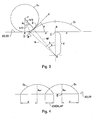
- Fig. 3 schematically depicts two ink drops D 1 and D 2 ejected onto the surface 20 of the ITM 22.
- the ink drops D 1 , D 2 assume a shape, upon contacting the ITM surface 20 during inkjet printing, that substantially minimizes their individual surface energies ⁇ D .
- the shape that the drops obtain upon contacting the ITM surface 20 includes that of a spherical cap (such as, e.g., the ink drop D 1 as shown in Fig. 3 ).
- the ink drop D 1 shaped as a spherical cap is substantially circular and has a radius p.
- the other ink drop D 2 ejected adjacent to the spherical cap D 1 has a radius R d .
- Fig. 3 further shows a contact point B of the ink drop D 1 (referred to herein as the "first ink drop”) and a deposition location A of the ink drop D 2 (referred to herein as the "second ink drop”).
- the contact point B of the first ink drop D 1 generally refers to a point located on the ink drop D 1 that the second ink drop D 2 may first contact when ejected onto the ITM 22.
- the contact point B may also be referred to as a point along the radius p of the ink drop D 1 that is furthest away from its center point E.
- the deposition location A of the second ink drop D 2 refers to a point on the ITM surface 20 that the second ink drop D 2 contacts when the ink drop D 2 is ejected thereon.
- the shortest distance AB is measured between the contact point B and the deposition location A, and may be used herein to determine the positioning of the second ink drop D 2 relative to that of the first ink drop D 1 so that coalescence is substantially eliminated. It is to be understood that if the second ink drop D 2 is ejected too close to the first ink drop D 1 , the second ink drop D 2 may contact the first ink drop D 1 prior to contacting the ITM surface 20 and coalescence between the ink drops D 1 , D2 may then occur. Such coalescence tends to result in a single larger ink drop having twice the volume of an initially ejected ink drop. As stated above, the coalescence between the ink drops D 1 , D 2 may deleteriously affect the print quality of the image transferred to the substrate.
- the ink drop D 2 may contact the ITM surface 20 prior to contacting the ink drop D 1 .
- the ink drop D 2 pins to the ITM surface 20 and forms a circular mark thereon. It is to be understood that although the ink drops D 1 and D 2 contact, such contact often results in overlapping (which generally does not deleteriously affect optical density of the resulting image); and not coalescence of the ink drops D 1 and D 2 .
- the overlapping of the ink drops will be described in further detail below in conjunction with Figs. 4 and 5 .
- the method includes drawing a tangent line from the contact point B through a surface point G located at the surface of the ink drop D 2 .
- the tangent line may also extend out to an arbitrary point C (as shown in Fig. 3 ).
- This tangent line is referred to herein as tangent line BC.
- the angle formed between the tangent line BC and the ITM surface 20 e.g., line BE) is referred to herein as the contact angle ⁇ .
- Point I along the outer surface of the drop D 2 represents an equidistant point between points A and G.
- the center point of the second ink drop D 2 is identified herein by reference character F.
- the deposition location A of the second ink drop D 2 may be determined by drawing a line from the center point F to the ITM surface 20. This line generally begins at the center point F and is perpendicular to the surface 20.
- the distance of each of lines FA, FI, and FG is equal to the radius R d of the second ink drop D 2 .
- Another line may be drawn from center point F of the second ink drop D 2 to point I of the second ink drop D 2 .
- the angle formed between the lines FA and FI is half of the contact angle ⁇ .
- the angle formed between the lines FI and a line defined between the center point F and the surface point G is also half of the contact angle ⁇ .
- the surface of the spherical cap formed by the ink drop D 1 when ejected onto the ITM 22 generally curves away from the tangent line BC.
- the shortest distance AB may, in some cases, be slightly overestimated because of this curvature.
- the distance between point E and point O is represented by Z, which equals R cos ⁇ .
- Z the distance between point E and point O
- a small contact angle ⁇ has a correspondingly small overestimation error.
- the overestimation error may be less than about 10% when the contact angle ⁇ is less than about 50°. In another non-limiting example, when ⁇ is 90°, the error is 10.3%.
- FIG. 4 a schematic illustration of the ink drops D 1 and D 2 after the ink drop D 2 contacts the ITM surface 20 and forms a spherical cap is depicted. As shown, when both drops D 1 , D 2 become spherical caps, there is a region on the surface 20 where the caps overlap (denoted by "overlap” in the Figure).
- the contact angle is influenced by both the extent of overlap between the drops D 1 , D 2 and the radius ratio of the drops D 1 , D 2 .
- the desired contact angle ⁇ may be determined using the normalized overlap or normalized radius ratio (both of which are measured in terms of percentage (%) as depicted in Fig. 5 ).
- the radius ratio when the contact angle is 1°, the radius ratio is about 0.15 (e.g., 0.148) and the overlap is about 50% (e.g., 0.499), and when the contact angle is 90°, the radius ratio is about 0.8 (e.g., 0.794) and the overlap is about 20% (e.g., 0.196).
- the data corresponding with the points shown in Fig. 5 are illustrated in the Table below.
- coalescence of adjacent ink drops may be substantially eliminated when the contact angle ⁇ is as low as possible (and thus overlap may be greater).
- the contact angle ⁇ is too high (such as, e.g., above 60°) and overlap is decreased, the transfer of the printed image onto a paper substrate may, in some instances, present a challenge.
- the highest percentage of overlap that may be used and still provide suitable print quality is about 80%.
- the desirable percentage of overlap between two adjacent drops may depend upon the level of ink coverage and the image to be produced. For example, when low ink coverage is used, little or no overlap between the drops may be desirable in order to obtain a desirable optical density of the image.
- the overlap may range from 0% (i.e., no overlap) up to 80%. Accordingly, the overlap between the ink drops D 1 and D 2 may be balanced with the contact angle ⁇ in order to achieve the reduced or substantially eliminated coalescence between the ink drops without deleteriously affecting print quality (e.g., optical density) of the printed image.
- print quality e.g., optical density
- the contact angle may otherwise be determined using the drop radius-to-cap radius ratio (R d / ⁇ ) curve shown Fig. 5 .
- the radius R d of the second ink drop D 2 is more than about 70% of the radius ⁇ of the spherical cap D 1 .
- an ink drop (e.g., the ink drop D 2 ) having a high contact angle ⁇ (e.g., greater than 70°) may have more physical clearance from the spherical cap D 1 .
- an ink drop having a lower contact angle ⁇ (e.g., less than 70°) will result in a smaller drop radius-to-cap radius ratio and will stay a greater distance from the spherical cap D 1 and, thus, have less overlap.
- ink drops D 2 having the lower contact angle will be more likely to overlap with the spherical cap D 1 .
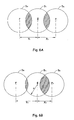
- Fig. 6A illustrates the desirable nominal overlap (illustrated by the shaded areas) between adjacent drops D 1 , D 2 and D 1 , D 3 .
- Fig. 6B illustrates the desirable maximum overlap between adjacent drops (see the shaded area between drops D 1 and D 3 ) and the desirable minimum overlap between adjacent drops (see the shaded area between drops D 1 and D 2 ).
- the range from the maximum overlap to minimum overlap provides the tolerance for the placement of the ink drops D 1 , D 2 , D 3 on the ITM 22.
- Equation 8 The maximum overlap may be calculated using Equation 8, and the minimum overlap may be calculated using Equation 9.
- a desired contact angle ⁇ of less than or equal to 50° reduces or substantially eliminates coalescence of adjacent ink drops ejected onto the ITM 22.
- the desired contact angle ⁇ ranges from about 35° to about 55°.
- the sequence of snapshots shown in the Figure 7 series illustrates coalescence of adjacent ink drops ejected onto an ITM during inkjet printing, where the contact angle ( ⁇ ) of the ink drops was higher (i.e., about 90°) than the desired contact angle disclosed herein.
- the ITM used for receiving the ink drops was selected from an elastomeric low surface energy material.
- carbon loaded polydimethylsiloxane (PDMS) was used, but other suitable media include fluoroelastomers, fluorosilicon elastomers, or the like.
- the ink drops depicted in the snapshots shown in the Figure 7 series were ejected onto the ITM using a thermal inkjet pen/ejector at a constant rate of 100 ⁇ sec between ejection of each ink drop.
- the ITM was moving orthogonal to the direction of the motion of the ink, which was ejected from the inkjet pen at room temperature (e.g., about 23°C).
- the snapshots were taken using a microscope camera as the ink drops were ejected onto the ITM.
- Fig. 7A shows the location of a first ink drop (e.g., D 1 ) on the ITM 22, which was continuously moving to the right-hand-side (as depicted) during inkjet printing.
- Fig. 7B shows ejection of a second ink drop (e.g., D 2 ) next to the first ink drop D 1 .
- Fig. 7C shows coalescence of the first and second ink drops resulting in a single larger ink drop.
- the sequence of snapshots shown in the Fig. 8 series illustrates how coalescence of adjacent ink drops is substantially eliminated when the ink drops have a desired contact angle ⁇ (in this example, about 50°).
- the ink drops were ejected onto the ITM under the same conditions and using the same procedure as described above for the snapshots shown in the Figure 7 series.
- the first and second ink drops each have their own footprint on the ITM because the second ink drop pins to the ITM surface 20 before touching the first ink drop.
- the desired contact angle ⁇ may be obtained by controlling the surface energy ⁇ of the inkjet ink and/or of the ITM surface 20. It is to be understood that the desired contact angle ⁇ of the ink drop D 1 , D 2 on the ITM 22 is based, at least in part, on the surface energies ⁇ D1 , ⁇ D2 of the ink drops D 1 , D 2 , respectively, and the surface energy ⁇ ITM of ITM surface 20.
- Equation (11) also known as Young's Equation
- ⁇ ITM ⁇ D ⁇ cos ⁇ + ⁇ Interface
- ⁇ ITM the surface energy of the ITM 22
- ⁇ D the surface energy of one of the ink drops D 1 , D 2
- ⁇ Interface the surface free energy at the interface formed between the ink drop and the ITM 22
- ⁇ is the contact angle.
- the surface energy ⁇ D of the inkjet ink may be controlled by including a certain combination of selected components into the inkjet ink formulation, where the presence of such components would render wetting properties of the inkjet ink as substantially less favorable for coalescence with adjacent ink drops.
- examples of such components included in the inkjet ink formulation include a certain combination of specific additives and co-solvents.
- the inkjet ink includes one or more colorants dispersed in an ink vehicle.
- the term "colorant" refers to a pigment, a dye, or combinations thereof.
- Suitable pigments include self-dispersed pigments, non-self-dispersed pigments, and polymer-encapsulated pigments.
- Self-dispersed pigments include those that have been chemically modified at the surface with a charge or a polymeric grouping. This chemical modification aids the pigment in becoming and/or substantially remaining dispersed in a liquid.
- the pigment selected for the ink may be a self-dispersible anionic pigment.
- Such pigments are made self-dispersable by the incorporation of carboxylate and/or sulfonate functionalities.
- the anionic pigments may be associated with Na + , Li + , and NH 4 + cations, although other suitable counter-ions may be used herein.
- Some non-limiting examples of self-dispersed pigments include anionic pigments selected from sulfonated copper phthalocyanine (CuPc), carboxylated CuPc, carboxylated carbon black pigments, and cationic amine-functionalized pigments.
- a non-self-dispersed pigment utilizes a separate and unattached dispersing agent (e.g., polymers, oligomers, surfactants, etc.) in the ink vehicle or physically coated on the surface of the pigment.
- a separate and unattached dispersing agent e.g., polymers, oligomers, surfactants, etc.
- the presence of such dispersing agents generally prevents the pigment from settling out of the ink vehicle.
- Non-limiting examples of suitable dispersing agents include anionic surfactants (such as, e.g., sodium dodecyl sulfate (SDS), sodium dioctyl sulfosuccinate (AOT), sodium laureth ether sulfate (SLES), alkyl benzene sulfonates, perfluorosctonoate (PFO), and fatty acid salts), cationic surfactants (such as, e.g., cetyltrimethylammonium bromide (CTAB), cetylpyridinium (CPC), benzalkonium chloride (BAC), and benzethonium chloride (BZT)), or a combination of ionic and non-ionic surfactants (such as, e.g., alkyl poly(ethylene oxide), alkylphenol poly(ethylene oxide), poloxamers, alkyl polyglucosides, and fatty alcohols).
- Another suitable dispersing agent includes cationic surfactants
- pigments for the ink include pigment cyan (PB) 15:3, pigment cyan (PB) 15:4, pigment magenta (PR) 122, pigment yellow (PY) 155, PY 74, pigment red (PR) 168, pigment green (PG) 36, pigment violet (PV) 23, carbon black (black), white pigment (TiO 2 ), silica, inorganic pigments, and polymer-encapsulated pigments.
- Examples of other suitable black pigments include Raven 7000, Raven 5750, Raven 5250, Raven 5000, and Raven 3500 (all of which are commercially available carbon black pigments from Columbian Chemicals, Co. located in Marietta, GA).
- Other examples of suitable black pigments include Color Black FW 200, Color Black FW 2, Color Black FW 2V, Color Black FW 1, Color Black FW 18, Color Black S 160, Color Black S 170, Special Black 6, Special Black 5, Special Black 4A, Special Black 4 (all of which are commercially available from Degussa Corp. located in Parsippany, NJ), and self-dispersed black pigments such as Cabo-Jet® 200 and Cabo-Jet® 300, manufactured by Cabot Corporation, located in Bellrica, MA.
- suitable classes of colored pigments include, but are not limited to anthraquinones, phthalocyanine blues, phthalocyanine greens, diazos, monoazos, pyranthrones, perylenes, heterocyclic yellows, quinacridones, and (thio)indigoids.
- phthalocyanine blues include copper phthalocyanine blue and derivatives thereof (e.g., PB15).
- quinacridones include, but are not limited to pigment orange (PO) 48, PO49, PR122, PR192, PR202, PR206, PR207, PR209, pigment violet (PV) 19, PV42, or combinations thereof.
- Non-limiting examples of anthraquinones include PR43, PR194 (perinone red), PR216 (brominated pyrathrone red), PR226 (pyranthrone red), or combinations thereof.
- Perylene pigment examples include, but are not limited to PR123 (vermillion), PR149 (scarlet), PR179 (maroon), PR190 (red), PR189 (yellow shade red), PR224, or combinations thereof.
- Non-limiting examples of thioindigoids include PR86, PR87, PR88, PR181, PR198, PV36, PV38, or combinations thereof.
- suitable heterocyclic yellow pigments include, but are not limited to PY117, PY138, or combinations thereof. Examples of other suitable colored pigments are described in Colour Index, 3rd edition (The Society of Dyers and Colourists, 1982 ).
- the pigment includes particles having a particle size (in terms of diameter) ranging from about 10 nm to about 500 nm.
- the pigment is present in the inkjet ink in an amount ranging from about 0.5 wt% to about 10 wt% of the inkjet ink.
- the pigment is present in the inkjet ink in an amount ranging from about 2 wt% to about 6 wt% of the inkjet ink.
- the dispersing agent is present in the inkjet ink in an amount ranging from about 0.5 wt% to about 15 wt% of the inkjet ink.
- the dispersing agent is present in an amount ranging from about 3 wt% to about 5 wt% of the inkjet ink.
- suitable dyes include yellow dyes (such as, e.g, AY-17, DY-132, DY-11, DY-12, Y-104, and/or combinations thereof), magenta dyes (such as, e.g., acid red 52, acid rhodamine B, reactive red 180, acid red 289, acid red 249, M-377, and/or combinations thereof), cyan dyes (such as, e.g., AB-9, DB-199, and/or combinations thereof), and black dyes (such as, e.g., water soluble metal complex azo dyes such as Reactive Black 31 and Reactive Black 8, water soluble polyazo dyes such as Direct Black 19, Direct Black 195, and Direct Black 168, water soluble sulfur dyes such as Solubilized Sulfur Black 1, materials such as carbon black or derivatives of carbon black, graphite, graphite oxide, and pRB31).
- the amount of dye present in the inkjet ink ranges from
- the inkjet ink may include, for example, a total pigment and dye amount ranging from about 0.5 wt% to about 4 wt%, where the pigment is present in a greater amount than the dye.
- the term "ink vehicle” refers to the combination of one or more solvents to form a vehicle in which the colorant(s) is/are placed to form the ink composition.
- the ink vehicle includes water in combination with one or more other solvents.
- Such ink vehicles are referred to herein as aqueous ink vehicles.
- the ink vehicle includes organic co-solvents or humectants, wetting agents or surfactants, a biocide, and water.
- the organic co-solvents or humectants are used in the inkjet ink to control evaporation or drying of the ink.
- the organic co-solvents are dipolar aprotic solvents selected from 2-pyrrolidone and N-methyl-2-pyrrolidone, diols (such as, e.g., 1,2-hexanediol), polyols (such as, e.g., sorbitol, xylitol, and propylene glycol), glyceryl triacetate, glycerine, and combinations thereof.
- the amount of organic co-solvents are present in the inkjet ink in an amount ranging from about 0.5 wt% to about 15 wt% of the inkjet ink. In another non-limiting example, the organic co-solvents are present in the inkjet ink in an amount ranging from about 8 wt% to about 15 wt% of the inkjet ink. Furthermore, in an example, any of the listed organic co-solvents may be included as a humectant, and when used as such, the amount present in the inkjet ink ranges from about 0.5 wt% to about 30 wt%.
- the wetting agent(s) or surfactant(s) are included in the inkjet ink to assist in controlling the physical properties of the ink, such as jetting stability, waterproofness and bleeding.
- One or more wetting agents or surfactants may be used in the formulation of the inkjet ink.
- the amount of the wetting agent(s) or surfactant(s) used in the inkjet ink ranges from about 1 wt% to about 20 wt% of the inkjet ink.
- the amount of the wetting agent(s) or surfactant(s) used ranges from about 3 wt% to about 5 wt% of the inkjet ink.
- the wetting agent(s) or surfactant(s) used in the inkjet ink may be nonionic or anionic, and are generally water-soluble organic ethers or alcohols.
- nonionic surfactants may suitably be used in the formulation of the ink, examples of which include ethoxylated alcohols such as those from the Tergitol® series (e.g., Tergitol® 1555, Tergitol® 15S7), manufactured by Union Carbide, located in Houston, TX; surfactants from the Surfynol® series (e.g.
- Surfynol® 440 and Surfynol® 465) manufactured by Air Products and Chemicals, Inc., located in Allentown, PA; fluorinated surfactants, such as those from the Zonyl® family (e.g., Zonyl® FSO and Zonyl® FSN surfactants), manufactured by E.I. duPont de Nemours Company, located in Wilmington, DE; fluorinated PolyFox® nonionic surfactants (e.g., PG-154 nonionic surfactants), manufactured by Omnova, located in Fairlawn, OH; 2-diglycol surfactants, such as 1,2 hexanediol or 1,2-octanediol; or combinations thereof.
- fluorinated surfactants such as those from the Zonyl® family (e.g., Zonyl® FSO and Zonyl® FSN surfactants), manufactured by E.I. duPont de Nemours Company, located in Wilmington, DE; fluor
- Suitable anionic surfactants that may be used in the ink composition include surfactants of the Dowfax® family (e.g., Dowfax® 8390), manufactured by Dow Chemical Company, located in Midland, MI, anionic Zonyl® surfactants (e.g., Zonyl® FSA), manufactured by E.I. duPont de Nemours Company; or combinations thereof, sodium laureth ether sulfate (SLES), or sodium dodecyl sulfate (SDS).
- Dowfax® family e.g., Dowfax® 8390
- anionic Zonyl® surfactants e.g., Zonyl® FSA
- SLES sodium laureth ether sulfate
- SDS sodium dodecyl sulfate
- the inkjet ink formulation may further include a biocide to inhibit possible microbial growth within the inkjet ink.
- a biocide to inhibit possible microbial growth within the inkjet ink.
- the biocide include ProxelTM biocides (manufactured by Arch Chemicals, Inc., Norwalk, CT), Troysan ® biocides (manufactured by Troy Corporation, Florham Park, NJ), BiochekTM biocides (manufactured by Etosha Pan, New Delhi, India), Nipacide biocides (manufactured by Clariant UK, Ltd, United Kingdom), Ucarcide (manufactured by the Dow Chemical Company, Midland, MI), Preventol (manufactured by Bayer AG, Leverbusen, Germany), Dowicil (manufactured by the Dow Chemical Company), and Tolcide ® biocides (manufactured by Rhodia, Courbevoie, France).
- the biocide may be present in the inkjet ink in an amount up to about 1 wt% of the inkjet ink. In another non-limiting example, the amount of biocide is present in an amount ranging from about 0.05 wt% to about 1 wt%.
- the specific additives that may be included in the inkjet ink formulation to achieve the desired surface energy ( ⁇ D ) of the ink include i) a hydantoin glycol, ii) a hyperbranched glycol, iii) a fluorosurfactant, and iv) an organic phosphate.
- the foregoing additives may be used in the inkjet ink formulation alone or in various combinations.
- the hydantoin glycol may be selected from any suitable hydantoin glycols having a hydroxyl value ranging from about 450 to about 550.
- hydantoin glycols include di-(2-hydroxyethyl)-5,5-dimethylhydantoin, hydantoin-5-acetic acid, Allantoin (i.e., 5-ureidohydantoin), L-Aspartic acid hydantoin, and combinations thereof.
- the hydantoin glycol is present in the inkjet ink in an amount ranging from about 1 wt% to about 15 wt% of the inkjet ink.
- the hyperbranched glycol may be selected from ethyl glycol, diethylene glycol, ethylene glycol butyl ether, ethylene glycol-bis(2-aminoethylether)-N,N,N',N'-tetraacetic acid, poly(ethylene glycol)-block-poly(propylene glycol)-block-poly(ethylene glycol) (such as, e.g., Synperonic ® F108, manufactured by Unichema Chemie BV, Netherlands), and combinations thereof.
- the amount of the hyperbranched glycol present in the inkjet ink ranges from about 0.5 wt% to about 10 wt% of the inkjet ink.
- the hyperbranched glycol is present in an amount ranging from about 0.5 wt% to about 5 wt%.
- the fluorosurfactant may be selected from surfactants of the Zonyl ® family (e.g., Zonyl ® FSO surfactants), manufactured by E.I. duPont de Nemours Company, Wilmington, DE; PolyFox ® surfactants (e.g.,PolyFox ® AT), manufactured by Omnova, located in Fairlawn, OH; Masurf ® surfactants (e.g., Masurf ® FS) manufactured by Mason Chemical Company, Arlington Heights, IL; and fluorosurfactants manufactured by Advanced Polymer, Inc, Carkstadt, NJ (e.g., APFS-14, APFS-17, and APFS-24).
- Zonyl ® FSO surfactants e.g., Zonyl ® FSO surfactants
- PolyFox ® surfactants e.g.,PolyFox ® AT
- Masurf ® surfactants e.g., Masurf ® FS
- the fluorosurfactant may be used alone in the inkjet ink formulation or in combination with one or more of the other surfactants that may be present in the inkjet ink as recited above.
- the fluorosurfactant is present in the inkjet ink in an amount ranging from about 0.01 wt% to about 2 wt% of the inkjet ink. In another non-limiting example, the fluorosurfactant is present in an amount ranging from about 0.01 wt% to about 1 wt% of the inkjet ink.
- the organic phosphate may be selected from oleth-3 phosphate, PPG-S ceteth-10 phosphate, linoleamidopropyl PG-dimonium chloride phosphate, trideceth-5 phosphate, oleth-5 phosphate, and combinations thereof.
- the amount of the organic phosphate present in the inkjet ink ranges from about 0.2 wt% to about 2 wt% of the inkjet ink.
- the inkjet ink further includes water.
- the amount of water is present in the inkjet ink in an amount ranging from about 40 wt% to about 90 wt% of the inkjet ink.
- the amount of water is present in the inkjet ink in an amount ranging from about 60 wt% to about 80 wt% of the inkjet ink.
- the amount of water may be increased or decreased as desired.
- achieving the desirable contact angle ⁇ may be obtained by controlling the surface energy ⁇ D of the inkjet ink and/or the surface energy ⁇ ITM of the ITM surface 20. This may be accomplished by i) decreasing the surface energy ⁇ D of the inkjet ink, ii) increasing the surface energy ⁇ ITM of the ITM surface 20, or iii) combinations thereof (such as, e.g., a combination of decreasing the surface energy ⁇ D of the inkjet ink and increasing the surface energy ⁇ ITM of the ITM surface 20). It is to be understood that one or more of the surface energies ⁇ D , ⁇ ITM may be adjusted as reasonable in order to achieve the desired contact angle ⁇ .
- the surface energy ⁇ D of the inkjet ink may be decreased by adjusting the amount of one or more components present in the inkjet ink.
- the amount of the hydantoin glycol, the hyperbranched glycol, and/or the fluorosurfactant present in the inkjet ink may be adjusted. It is to be understood that the adjusting of the amount of one or more of the above-listed components of the inkjet ink is based, at least in part, on the surface energy ⁇ ITM of the ITM surface 20.
- the amount of the above-listed components of the inkjet ink may be adjusted to reduce the surface energy ⁇ D of the inkjet ink until the surface energy of the ink matched/substantially matched the surface energy of the ITM 22, and the desired contact angle ⁇ is obtained.
- the surface energy ⁇ D of the inkjet ink may be decreased by increasing the amount of the fluorosurfactant in the inkjet ink formulation.
- the fluorosurfactant may be increased in an amount ranging from about 0.05 wt% to about 15 wt% higher than the original amount in order to achieve the desired surface energy ⁇ D .
- the fluorosurfactant may be increased in an amount ranging from about 0.1 wt% to about 5 wt% higher than the original amount to achieve the desired surface energy ⁇ D .
- the fluorosurfactant amount may be increased, e.g., by about 0.5 wt% to about 2 wt%, while maintaining the amounts of the other components in the ink.
- the presence of the fluorosurfactant increases the interaction of the ink (specifically the co-solvents and the colorant (i.e., the pigment and/or the dye) of the ink) with the ITM surface 20, thereby reducing the contact angle.
- the surface energy ⁇ D of the inkjet ink may otherwise be increased by removing at least one of the hydantoin glycol or the hyperbranched glycol. It is to be understood that one or more of the foregoing elements may be removed from the inkjet ink formulation as necessary in order to adjust or tweak the surface energy ⁇ D to match that of the ITM 22 selected.
- the surface energy ⁇ D of the inkjet ink may be decreased by actually replacing one or more of the organic solvents, the hydantoin glycol, or the hyperbranched glycol with at least one other element that is more hydrophobic than the component being replaced.
- a more hydrophobic component to include in the ink composition in place of a solvent, hydantoin glycol, or hyperbranched glycol, it is to be understood that the selected component should promote interaction with the ITM 22.
- the component replacing the solvent, hydantoin glycol, or hyperbranched glycol may interact with water molecules present in the inkjet ink. Such interaction often affects the surface energy of the ink.
- the interaction with the water molecules and the replacement component(s) is at least the same level of interaction as that of the component that the replacement component(s) is/are replacing.
- any active functional group e.g., hydroxyl groups, carboxyl groups, etc.
- one of the co-solvents present in the inkjet ink may be replaced with one or more other solvents that are more hydrophobic than the original one co-solvent.
- the original co-solvent is a hyperbranched glycol having X number of carbons in one of the branched chains
- the replacement solvent is the same hyperbranched glycol except the branched chain with X carbons is replaced with a longer aliphatic hydrocarbon chain (i.e., more carbons than X).
- the components replacing one or more of the co-solvent, hydantoin glycol, or the hyperbranched glycol may be used in substantially the same loading as the replaced element.
- the amount of the replacement component depends, at least in part, on the desired contact angle ⁇ and, in most instances, the loading of the replacement component(s) is significantly different from the loading of the component(s) being replaced.
- the surface energy ( ⁇ ITM may, in some instances, be too low (such as, e.g., less than about 200 mJm -2 ), presenting difficulties in achieving the desired contact angle ⁇ in cases where the amount or formulation of the inkjet ink is not adjusted or changed.
- the surface energy ⁇ ITM of the ITM surface 20 may therefore be increased, for example, by making the ITM surface 20 less hydrophobic.
- the surface energy ⁇ ITM of the ITM surface 20 may be increased by subjecting the surface 20 to a plasma (such as, e.g., oxygen or a mixed gas) to introduce, e.g., hydroxyl groups to the ITM surface 20.
- a plasma such as, e.g., oxygen or a mixed gas
- the surface energy ⁇ ITM of the ITM surface 20 may otherwise be increased, for example, by incorporating particles into the ITM 22 matrix, where such particles are covalently bonded to at least one terminating group.
- the amount of the particles incorporated into the ITM 22 matrix is sufficient to obtain the desired contact angle ⁇ and depends, at least in part, on the surface energy ⁇ D of the inkjet ink.
- Non-limiting examples of terminating groups that may be covalently bonded to the particles include at least one carboxylic terminating group, at least one hydroxyl terminating group, at least one sulfonate group, or combinations thereof. For instance, as shown in Fig.
- nanoparticles of carbon black having carboxylic terminating group(s) may be incorporated into the ITM 22 matrix in an amount sufficient to obtain the desired contact angle ⁇ .
- the amount of the nanoparticles incorporated into the ITM 22 matrix ranges from about 5 wt% to about 20 wt%.
- the particles may be incorporated into the ITM 22 matrix during manufacturing thereof, but prior to curing and hardening.
- the particles e.g., carbon black
- the particles are incorporated into the ITM 22 matrix by applying a layer including a mixture of carbon loaded materials for the ITM 22 matrix onto the ITM surface 20 using, e.g., a doctor blade, followed by a curing process. After curing, the carbon loaded layer may be laminated, thereby forming a thin film on the ITM surface 20.
- the desired contact angle ⁇ may be obtained by controlling the evaporation of the water from the ink drops. Such may be accomplished, for example, by reducing the amount of humectants present in the inkjet ink. Without being bound to any theory, it is believed that when the evaporation of the water from the ink drops is increased, the colorant present in the inkjet ink formulation producing the drops pins to the surface 20 of the ITM 22. As used herein, the terms “pin” and “pinning” refer to the fixing of at least the colorant present in the ink onto the ITM surface 20.
- Pinning occurs as a result of, at least in part, Van de Waals interaction between the colorant and the ITM surface 20 generated. As described herein, such interaction is increased when the surface energy of the ink matches the surface energy of the ITM surface 20. More specifically, the surface energy of the ink causes the ink drop to localize on the ITM surface 20. After the water (and possibly other solvents) in the ink evaporate, the remaining components (e.g., colorant) are set where printed. In some instances, the evaporation is increased to an amount that is on par with that of water present in the inkjet ink as a result of the surface energy.
Landscapes
- Chemical & Material Sciences (AREA)
- Life Sciences & Earth Sciences (AREA)
- Engineering & Computer Science (AREA)
- Materials Engineering (AREA)
- Wood Science & Technology (AREA)
- Organic Chemistry (AREA)
- Ink Jet (AREA)
- Inks, Pencil-Leads, Or Crayons (AREA)
- Ink Jet Recording Methods And Recording Media Thereof (AREA)
Claims (18)
- En combinaison, une encre pour jet d'encre (18) et un support de transfert intermédiaire (22) pour une impression à jet d'encre, l'encre pour jet d'encre (18) formant des gouttes d'encre (D1, D2) ayant un angle de contact (θ) inférieur ou égal à 50° sur le support de transfert intermédiaire (22), une propriété d'au moins l'une de l'encre pour jet d'encre (18) ou d'une surface (20) du support de transfert intermédiaire (22) étant contrôlable pour obtenir l'angle de contact (θ).
- Combinaison telle que définie dans la revendication 1 dans laquelle la propriété comprend une énergie de surface (γ, γD1, γD2) de la goutte d'encre (D1, D2), une énergie de surface (γITM) de la surface (20) du support de transfert intermédiaire (22), ou les combinaisons de celles-ci.
- Combinaison telle que définie dans l'une quelconque des revendications 1 ou 2 dans laquelle l'encre pour jet d'encre (18) comprend un colorant dispersé dans un véhicule d'encre, le véhicule d'encre comprenant :un hydantoïne glycol présent dans l'encre dans une quantité allant de 1 % en poids à 15 % en poids, l'hydantoïne glycol ayant un indice d'hydroxyle allant de 450 à 550 ;un solvant aprotique dipolaire présent dans l'encre dans une quantité allant de 0,5 % en poids à 15 % en poids ;un glycol hyper-ramifié présent dans l'encre dans une quantité allant de 0,5 % en poids à 10 % en poids ;un tensio-actif fluoré présent dans l'encre dans une quantité allant de 0,01 % en poids à 2 % en poids ;un phosphate organique présent dans l'encre dans une quantité allant de 0,2 % en poids à 2 % en poids ; etde l'eau.
- Combinaison telle que définie dans la revendication 3, dans laquelle :l'hydantoïne glycol est choisi parmi le di-(2-hydroxyéthyl)-5,5-diméthylhydantoïne, l'acide hydantoïne-5-acétique, l'allantoïne, l'acide L-aspartique hydantoïne, et les combinaisons de ceux-ci ;le solvant organique est un solvant aprotique dipolaire choisi parmi la 2-pyrrolidone, une N-méthyl-2-pyrrolidone, les diols, les polyols, le triacétate de glycéryle, le glycérol et les combinaisons de ceux-ci ;le glycol hyper-ramifié est choisi parmi l'éthyl glycol, le diéthylène glycol, l'éther butylique de l'éthylène glycol, l'acide éthylène glycol-bis(20aminoéthyléther)-N,N,N',N'-tétraacétique, le poly(éthylène glycol)-bloc-poly(propylène glycol)-bloc-poly(éthylène glycol) et les combinaisons de ceux-ci ; etle phosphate organique est choisi parmi l'oleth-3 phosphate, le PPG-S céteth-10 phosphate, le phosphate de chlorure de linoléamidopropyl PG-dimonium, le tridéceth-5 phosphate, l'oleth-5 phosphate et les combinaisons de ceux-ci.
- Combinaison telle que définie dans l'une quelconque des revendications 3 ou 4 dans laquelle l'encre pour jet d'encre (18) comprend en outre un biocide présent dans l'encre dans une quantité allant de 0,05 % en poids à 1 % en poids.
- Combinaison telle que définie dans l'une quelconque des revendications précédentes dans laquelle la surface (20) du support de transfert intermédiaire (22) comprend une matrice dans laquelle ont été incorporées des particules liées de façon covalente à au moins un groupe de terminaison dans une quantité suffisante pour obtenir l'angle de contact (θ).
- Combinaison telle que définie dans la revendication 6 dans laquelle l'au moins un groupe de terminaison est choisi parmi au moins un groupe de terminaison carboxylique, au moins un groupe de terminaison hydroxyle, au moins un groupe sulfonate et les combinaisons de ceux-ci.
- Système d'impression à jet d'encre (10), comprenant un éjecteur de fluide pour jet d'encre (14) couplé fluidiquement à un réservoir (16) contenant une encre pour jet d'encre (18), l'éjecteur de fluide (14) étant configuré pour éjecter l'encre pour jet d'encre (18) sur un support de transfert intermédiaire (22) durant une impression à jet d'encre, dans lequel le système d'impression à jet d'encre (10) est configuré pour réaliser un procédé, comprenant :l'éjection, par l'intermédiaire de l'éjecteur de fluide pour jet d'encre (14), de l'encre pour jet d'encre (18) sur le support de transfert intermédiaire (22) ; etla réduction ou l'élimination substantielle d'une coalescence entre les gouttes d'encre adjacentes (D1, D2) lorsque les gouttes d'encre (D1, D2) sont éjectées sur le support de transfert intermédiaire (22), la réduction ou l'élimination substantielle de la coalescence étant accomplie par :la détermination d'un angle de contact (θ) des gouttes d'encre (D1, D2) sur le support de transfert intermédiaire (22) ; etle contrôle d'au moins l'une d'une propriété de l'encre pour jet d'encre (18) ou d'une propriété d'une surface (20) du support de transfert intermédiaire (22) pour obtenir l'angle de contact (θ), l'angle de contact (θ) étant inférieur ou égal à 50°.
- Système d'impression à jet d'encre (10) tel que défini dans la revendication 8 dans lequel l'encre pour jet d'encre (18) comprend :un véhicule d'encre, comprenant :un hydantoïne glycol ayant un indice d'hydroxyle allant de 450 à 550 ;un solvant organique ;un glycol hyper-ramifié ;un tensio-actif fluoré ;un phosphate organique ; etde l'eau ; etun colorant dispersé dans le véhicule d'encre.
- Système d'impression à jet d'encre (10) tel que défini dans l'une quelconque des revendications 8 ou 9 dans lequel l'angle de contact (θ) est inférieur ou égal à 50°.
- Système d'impression à jet d'encre (10) tel que défini dans l'une quelconque des revendications 8 à 10 dans lequel le contrôle de l'au moins une de la propriété de l'encre pour jet d'encre (18) ou de la propriété de la surface (20) du support de transfert intermédiaire (22) comprend la diminution de l'énergie de surface (γ, γD1, γD2) de l'encre pour jet d'encre (18), l'augmentation de l'énergie de surface (γITM) de la surface (20) du support de transfert intermédiaire (22), ou les combinaisons de celles-ci.
- Système d'impression à jet d'encre (10) tel que défini dans la revendication 11 dans lequel la diminution de l'énergie de surface (γ, γD1, γD2) de l'encre pour jet d'encre (18) est accomplie par i) ajustement de la quantité d'au moins l'un parmi l'hydantoïne glycol, le glycol hyper-ramifié, ou le tensio-actif fluoré présent dans l'encre, ou ii) remplacement d'au moins l'un de l'hydantoïne glycol ou du glycol hyper-ramifié par au moins un autre élément.
- Système d'impression à jet d'encre (10) tel que défini dans la revendication 11 dans lequel l'augmentation de l'énergie de surface (γ, γD1, γD2) de la surface (20) du support de transfert intermédiaire (22) comprend la soumission de la surface (20) à un plasma, permettant par là d'introduire ainsi des groupes hydroxyle sur la surface dans une quantité suffisante pour obtenir l'angle de contact (θ).
- Système d'impression à jet d'encre (10) tel que défini dans l'une quelconque des revendications 8 à 13 dans lequel le contrôle comprend en outre l'augmentation de l'évaporation d'eau à partir des gouttes d'encre (D1, D2), permettant ainsi de fixer le colorant sur la surface (20) du support de transfert intermédiaire (22).
- Système d'impression à jet d'encre (10) tel que défini dans l'une quelconque des revendications 8 à 14 dans lequel la détermination de l'angle de contact (θ) est accomplie par :la détermination d'un volume (V, VD1, VD2) des gouttes d'encre (D1, D2) ;le calcul, par l'intermédiaire d'un processeur (30) associé de manière fonctionnelle au système d'impression à jet d'encre (10), d'une distance la plus courte (AB) entre un point de contact (B) d'une première goutte d'encre (D1) et un emplacement de dépôt (A) d'une seconde goutte d'encre (D2), une coalescence entre les première et seconde gouttes d'encre (D1, D2) étant sensiblement éliminée ;le calcul, par l'intermédiaire d'un processeur (30) associé de manière fonctionnelle au système d'impression à jet d'encre, de l'angle de contact (θ) sur la base de la distance la plus courte (AB) à l'aide la formule :

- Système d'impression à jet d'encre tel que défini dans la revendication 15 dans lequel le calcul de l'angle de contact est accompli par tracé d'une ligne tangente à partir du point de contact (B) sur la surface du support de transfert intermédiaire par un point de surface (G) situé au niveau d'une surface de la seconde goutte d'encre, l'angle formé entre la ligne tangente et la surface du support de transfert intermédiaire étant l'angle de contact (θ).
- Système d'impression à jet d'encre tel que défini dans la revendication 15 dans lequel la distance la plus courte (AB) est surestimée, et dans lequel le procédé comprend en outre la détermination d'une erreur de surestimation à l'aide la formule : Erreur = 1 - cosα, où

- Système d'impression à jet d'encre tel que défini dans la revendication 8 dans lequel la détermination de l'angle de contact (θ) est accomplie par au moins l'une parmi :i) la détermination d'une étendue de chevauchement entre les première et seconde gouttes d'encre à l'aide de la formule :
 ii) la détermination d'un rapport de rayon entre les première et seconde gouttes d'encre à l'aide de la formule :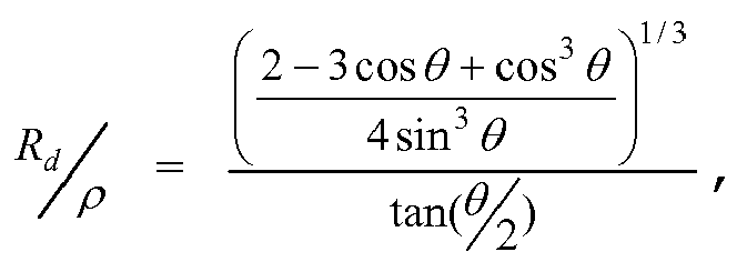
Applications Claiming Priority (1)
| Application Number | Priority Date | Filing Date | Title |
|---|---|---|---|
| PCT/US2009/052406 WO2011014185A1 (fr) | 2009-07-31 | 2009-07-31 | Encre pour jet d'encre et support de transfert intermédiaire pour impression à jet d'encre |
Publications (3)
| Publication Number | Publication Date |
|---|---|
| EP2459382A1 EP2459382A1 (fr) | 2012-06-06 |
| EP2459382A4 EP2459382A4 (fr) | 2014-01-01 |
| EP2459382B1 true EP2459382B1 (fr) | 2014-11-12 |
Family
ID=43529607
Family Applications (1)
| Application Number | Title | Priority Date | Filing Date |
|---|---|---|---|
| EP09847928.0A Not-in-force EP2459382B1 (fr) | 2009-07-31 | 2009-07-31 | Encre pour jet d'encre et support de transfert intermédiaire pour impression à jet d'encre |
Country Status (4)
| Country | Link |
|---|---|
| US (1) | US8714731B2 (fr) |
| EP (1) | EP2459382B1 (fr) |
| TW (1) | TW201107432A (fr) |
| WO (1) | WO2011014185A1 (fr) |
Families Citing this family (68)
| Publication number | Priority date | Publication date | Assignee | Title |
|---|---|---|---|---|
| US9048344B2 (en) | 2008-06-13 | 2015-06-02 | Kateeva, Inc. | Gas enclosure assembly and system |
| US12018857B2 (en) | 2008-06-13 | 2024-06-25 | Kateeva, Inc. | Gas enclosure assembly and system |
| US10434804B2 (en) | 2008-06-13 | 2019-10-08 | Kateeva, Inc. | Low particle gas enclosure systems and methods |
| US8899171B2 (en) | 2008-06-13 | 2014-12-02 | Kateeva, Inc. | Gas enclosure assembly and system |
| US12064979B2 (en) | 2008-06-13 | 2024-08-20 | Kateeva, Inc. | Low-particle gas enclosure systems and methods |
| US8383202B2 (en) | 2008-06-13 | 2013-02-26 | Kateeva, Inc. | Method and apparatus for load-locked printing |
| US11975546B2 (en) | 2008-06-13 | 2024-05-07 | Kateeva, Inc. | Gas enclosure assembly and system |
| US10632740B2 (en) | 2010-04-23 | 2020-04-28 | Landa Corporation Ltd. | Digital printing process |
| WO2013132418A2 (fr) | 2012-03-05 | 2013-09-12 | Landa Corporation Limited | Procédé d'impression numérique |
| EP2823006B1 (fr) | 2012-03-05 | 2020-09-30 | Landa Corporation Ltd. | Structures de films d'encre |
| US9902147B2 (en) | 2012-03-05 | 2018-02-27 | Landa Corporation Ltd. | Digital printing system |
| US10190012B2 (en) | 2012-03-05 | 2019-01-29 | Landa Corporation Ltd. | Treatment of release layer and inkjet ink formulations |
| US10642198B2 (en) | 2012-03-05 | 2020-05-05 | Landa Corporation Ltd. | Intermediate transfer members for use with indirect printing systems and protonatable intermediate transfer members for use with indirect printing systems |
| CN104271687B (zh) | 2012-03-05 | 2016-11-02 | 兰达公司 | 油墨膜构造 |
| CN112848683B (zh) | 2012-03-05 | 2023-11-14 | 兰达公司 | 数字打印系统的控制设备和方法 |
| WO2013132420A1 (fr) | 2012-03-05 | 2013-09-12 | Landa Corporation Limited | Système d'impression |
| US9568862B2 (en) | 2012-03-05 | 2017-02-14 | Landa Corporation Ltd. | Digital printing system |
| US9643403B2 (en) | 2012-03-05 | 2017-05-09 | Landa Corporation Ltd. | Printing system |
| US10434761B2 (en) | 2012-03-05 | 2019-10-08 | Landa Corporation Ltd. | Digital printing process |
| US9498946B2 (en) | 2012-03-05 | 2016-11-22 | Landa Corporation Ltd. | Apparatus and method for control or monitoring of a printing system |
| EP2822776B1 (fr) | 2012-03-05 | 2018-08-01 | Landa Corporation Ltd. | Procédé d'impression par transfert |
| CN109177531B (zh) | 2012-03-15 | 2020-11-27 | 兰达公司 | 打印系统的环形柔性皮带 |
| US9354557B2 (en) * | 2013-06-12 | 2016-05-31 | Canon Kabushiki Kaisha | Intermediate transfer member and image recording method |
| GB201401173D0 (en) | 2013-09-11 | 2014-03-12 | Landa Corp Ltd | Ink formulations and film constructions thereof |
| US9782993B2 (en) | 2013-09-11 | 2017-10-10 | Landa Corporation Ltd. | Release layer treatment formulations |
| US9157001B2 (en) | 2013-09-20 | 2015-10-13 | Xerox Corporation | Coating for aqueous inkjet transfer |
| US9376584B2 (en) | 2013-09-20 | 2016-06-28 | Xerox Corporation | Coating for aqueous inkjet transfer |
| US9273218B2 (en) | 2013-09-20 | 2016-03-01 | Xerox Corporation | Coating for aqueous inkjet transfer |
| US9126430B2 (en) | 2013-09-20 | 2015-09-08 | Xerox Corporation | System and method for image receiving surface treatment in an indirect inkjet printer |
| WO2015100375A1 (fr) | 2013-12-26 | 2015-07-02 | Kateeva, Inc. | Traitement thermique de dispositifs électroniques |
| WO2015112454A1 (fr) | 2014-01-21 | 2015-07-30 | Kateeva, Inc. | Appareils et techniques d'encapsulation de dispositifs électroniques |
| US9073357B1 (en) | 2014-03-19 | 2015-07-07 | Xerox Corporation | Indirect inkjet printer and blower for treatment of a hydrophilic layer on an image receiving surface in the indirect inkjet printer |
| KR102850075B1 (ko) | 2014-04-30 | 2025-08-25 | 카티바, 인크. | 가스 쿠션 장비 및 기판 코팅 기술 |
| CN104207799A (zh) * | 2014-08-29 | 2014-12-17 | 沈阳东软医疗系统有限公司 | 一种ct扫描设备中形状过滤器的控制方法及装置 |
| GB2536489B (en) | 2015-03-20 | 2018-08-29 | Landa Corporation Ltd | Indirect printing system |
| GB2537813A (en) | 2015-04-14 | 2016-11-02 | Landa Corp Ltd | Apparatus for threading an intermediate transfer member of a printing system |
| US9688079B2 (en) | 2015-07-06 | 2017-06-27 | Xerox Corporation | System and method for image receiving surface treatment in an indirect inkjet printer |
| US9604471B2 (en) | 2015-07-06 | 2017-03-28 | Xerox Corporation | System and method for operating an aqueous inkjet printer to coat media prior to printing images on the media with the aqueous inkjet printer |
| US11141995B2 (en) | 2015-12-28 | 2021-10-12 | The Procter & Gamble Company | Method and apparatus for applying a material onto articles with a pre-distorted transfer component |
| US20170182756A1 (en) | 2015-12-28 | 2017-06-29 | The Procter & Gamble Company | Method and apparatus for applying a material onto articles using a continuous transfer component |
| US10486368B2 (en) | 2015-12-28 | 2019-11-26 | The Procter & Gamble Company | Method for transferring material with adhesive onto articles with a difference in degree of curing between the material and adhesive |
| CN108430786B (zh) | 2015-12-28 | 2021-06-15 | 宝洁公司 | 使用在双侧上偏转的转移部件将材料施加到制品上的方法和设备 |
| GB201602877D0 (en) | 2016-02-18 | 2016-04-06 | Landa Corp Ltd | System and method for generating videos |
| GB201609463D0 (en) | 2016-05-30 | 2016-07-13 | Landa Labs 2012 Ltd | Method of manufacturing a multi-layer article |
| DE112017002714T5 (de) | 2016-05-30 | 2019-02-28 | Landa Corporation Ltd. | Digitales Druckverfahren |
| US10723138B2 (en) | 2017-03-23 | 2020-07-28 | Hewlett-Packard Development Company, L.P. | Printing systems |
| US10682837B2 (en) | 2017-06-09 | 2020-06-16 | The Proctor & Gamble Company | Method and compositions for applying a material onto articles |
| US20180354253A1 (en) | 2017-06-09 | 2018-12-13 | The Procter & Gamble Company | Method for Applying Material onto and Conforming to Three-Dimensional Articles |
| WO2019077489A1 (fr) | 2017-10-19 | 2019-04-25 | Landa Corporation Ltd. | Courroie flexible sans fin pour un système d'impression |
| WO2019099183A1 (fr) | 2017-11-17 | 2019-05-23 | The Procter & Gamble Company | Procédés pour appliquer un matériau sur des articles |
| JP7225230B2 (ja) | 2017-11-19 | 2023-02-20 | ランダ コーポレイション リミテッド | デジタル印刷システム |
| WO2019102297A1 (fr) | 2017-11-27 | 2019-05-31 | Landa Corporation Ltd. | Système d'impression numérique |
| US11707943B2 (en) | 2017-12-06 | 2023-07-25 | Landa Corporation Ltd. | Method and apparatus for digital printing |
| US11679615B2 (en) | 2017-12-07 | 2023-06-20 | Landa Corporation Ltd. | Digital printing process and method |
| EP3564042A3 (fr) | 2018-05-01 | 2020-01-22 | The Procter & Gamble Company | Procédés d'application d'un matériau réfléchissant sur des articles et articles doté d'un matériau réfléchissant |
| WO2020003088A1 (fr) | 2018-06-26 | 2020-01-02 | Landa Corporation Ltd. | Élément de transfert intermédiaire pour système d'impression numérique |
| US10994528B1 (en) | 2018-08-02 | 2021-05-04 | Landa Corporation Ltd. | Digital printing system with flexible intermediate transfer member |
| US12001902B2 (en) | 2018-08-13 | 2024-06-04 | Landa Corporation Ltd. | Correcting distortions in digital printing by implanting dummy pixels in a digital image |
| JP7252509B2 (ja) * | 2018-08-31 | 2023-04-05 | セイコーエプソン株式会社 | インクジェット方法及び記録装置 |
| JP7246496B2 (ja) | 2018-10-08 | 2023-03-27 | ランダ コーポレイション リミテッド | 印刷システムおよび方法に関する摩擦低減手段 |
| WO2020136517A1 (fr) | 2018-12-24 | 2020-07-02 | Landa Corporation Ltd. | Système d'impression numérique |
| CN111546760A (zh) | 2019-02-12 | 2020-08-18 | 宝洁公司 | 使用传送部件将材料施加到制品上的方法和设备 |
| EP3946953A4 (fr) | 2019-03-31 | 2022-12-14 | Landa Corporation Ltd. | Systèmes et procédés pour empêcher ou minimiser les défauts d'impression dans les processus d'impression |
| CN114746813A (zh) | 2019-11-25 | 2022-07-12 | 兰达公司 | 在数字印刷中使用红外辐射来干燥油墨 |
| US11321028B2 (en) | 2019-12-11 | 2022-05-03 | Landa Corporation Ltd. | Correcting registration errors in digital printing |
| EP4081866A4 (fr) | 2019-12-29 | 2024-01-03 | Landa Corporation Ltd. | Procédé et système d'impression |
| WO2021183350A1 (fr) | 2020-03-09 | 2021-09-16 | The Procter & Gamble Company | Procédé et appareil permettant d'appliquer un matériau sur des articles à l'aide d'un composant de transfert |
| EP4264377A4 (fr) | 2021-02-02 | 2024-11-13 | Landa Corporation Ltd. | Atténuation de distorsions dans des images imprimées |
Family Cites Families (16)
| Publication number | Priority date | Publication date | Assignee | Title |
|---|---|---|---|---|
| US5099256A (en) | 1990-11-23 | 1992-03-24 | Xerox Corporation | Ink jet printer with intermediate drum |
| US5160535A (en) * | 1991-01-11 | 1992-11-03 | Trident, Inc. | Rapidly drying impulse ink jet ink compositions |
| JP3223927B2 (ja) | 1991-08-23 | 2001-10-29 | セイコーエプソン株式会社 | 転写式記録装置 |
| US5188664A (en) | 1991-11-26 | 1993-02-23 | Hewlett-Packard Company | Anti-coalescent ink composition and method for making the same |
| US5600352A (en) | 1994-06-27 | 1997-02-04 | Tektronix, Inc. | Apparatus and method for controlling coalescence of ink drops on a print medium |
| US5972082A (en) * | 1996-04-30 | 1999-10-26 | Ricoh Company, Ltd. | Aqueous ink composition and ink-jet printing method using the same |
| JP3802616B2 (ja) | 1996-08-19 | 2006-07-26 | シャープ株式会社 | インクジェット記録方法 |
| JP3853006B2 (ja) * | 1997-01-31 | 2006-12-06 | 株式会社ユポ・コーポレーション | 水性インクジェット記録用紙 |
| US6086987A (en) | 1997-01-23 | 2000-07-11 | Oji-Yuka Synthetic Paper Co., Ltd. | Synthetic paper and inkjet recording paper with the use of the same |
| US6109746A (en) | 1998-05-26 | 2000-08-29 | Eastman Kodak Company | Delivering mixed inks to an intermediate transfer roller |
| US6357870B1 (en) | 2000-10-10 | 2002-03-19 | Lexmark International, Inc. | Intermediate transfer medium coating solution and method of ink jet printing using coating solution |
| US7494213B2 (en) | 2002-09-04 | 2009-02-24 | Canon Kabushiki Kaisha | Image forming process and image forming apparatus |
| KR100867045B1 (ko) * | 2003-06-23 | 2008-11-04 | 캐논 가부시끼가이샤 | 화상 형성 방법, 화상 형성 장치, 화상 형성 장치에 이용되는 중간 전사체 및 그 제조 방법 |
| JP2006130905A (ja) | 2004-10-08 | 2006-05-25 | Fuji Photo Film Co Ltd | 平版印刷方法 |
| DE602007009811D1 (de) | 2006-01-27 | 2010-11-25 | Harvard College | Koaleszenz fluider tröpfchen |
| JP2007268802A (ja) * | 2006-03-30 | 2007-10-18 | Fujifilm Corp | 画像形成装置及び画像形成方法 |
-
2009
- 2009-07-31 EP EP09847928.0A patent/EP2459382B1/fr not_active Not-in-force
- 2009-07-31 US US13/383,756 patent/US8714731B2/en active Active
- 2009-07-31 WO PCT/US2009/052406 patent/WO2011014185A1/fr not_active Ceased
-
2010
- 2010-07-30 TW TW099125339A patent/TW201107432A/zh unknown
Also Published As
| Publication number | Publication date |
|---|---|
| US8714731B2 (en) | 2014-05-06 |
| EP2459382A1 (fr) | 2012-06-06 |
| EP2459382A4 (fr) | 2014-01-01 |
| WO2011014185A1 (fr) | 2011-02-03 |
| TW201107432A (en) | 2011-03-01 |
| US20120105525A1 (en) | 2012-05-03 |
Similar Documents
| Publication | Publication Date | Title |
|---|---|---|
| EP2459382B1 (fr) | Encre pour jet d'encre et support de transfert intermédiaire pour impression à jet d'encre | |
| US7604692B2 (en) | Ink composition for ink jet recording, recording method, and recorded matter | |
| US8440010B2 (en) | Inkjet printing method and ink set | |
| EP2272924B1 (fr) | Encre aqueuse pour impression jet d encre | |
| US8263683B2 (en) | Ink for printing on low energy substrates | |
| CN101415787B (zh) | 喷墨记录用墨液组合物、记录方法和记录物 | |
| US7731789B2 (en) | Ink composition and ink jet recording method using the same | |
| EP0692527B1 (fr) | Assortiment d'encres et procédé d'enregistrement en couleur par jet d'encre en faisant usage | |
| EP2774771B1 (fr) | Liquide de pré-traitement et procédé de formation d'images | |
| EP2694605B1 (fr) | Ensemble d'encres d'enregistrement à jet d'encre, cartouche d'encre, dispositif d'enregistrement à jet d'encre, procédé d'enregistrement à jet d'encre et matière destinée à former une image | |
| EP2272925B1 (fr) | Encre aqueuse pour impression jet d encre | |
| EP2069443B1 (fr) | Composition d'encre pour impression à jet d'encre | |
| US8506067B2 (en) | Ink jet image-forming method, ink jet color image-forming method and ink jet recording apparatus | |
| JP5896107B2 (ja) | インクジェット用コート液およびこれを用いたインクジェット記録方法 | |
| EP2173823B1 (fr) | Encre d'impression à jet d'encre | |
| EP2343347A1 (fr) | Composition d encre utilisée à des fins d enregistrement par jet d encre | |
| JP5552995B2 (ja) | インクジェット記録用インク、インクカートリッジ、インクジェット記録装置、画像形成方法、画像形成物 | |
| CN105705340B (zh) | 印刷颜料基油墨的方法,用于其的油墨组、油墨及印刷机 | |
| EP2354197A1 (fr) | Encre à base d'eau pour enregistrement à jet d'encre | |
| US20110192317A1 (en) | Ink composition for ink jet recording | |
| EP2101902B1 (fr) | Encre pour impression à jet d'encre, jeu d'encres et procédé d'utilisation de ceux-ci | |
| WO2007019143A1 (fr) | Encres à pigments pour une image et une conservation excellentes | |
| JP2013129688A (ja) | インクジェット用インク組成物、記録方法及び記録物 | |
| US20120105550A1 (en) | Aqueous inkjet printing fluid compositions | |
| WO2006090825A1 (fr) | Composition d’encre |
Legal Events
| Date | Code | Title | Description |
|---|---|---|---|
| PUAI | Public reference made under article 153(3) epc to a published international application that has entered the european phase |
Free format text: ORIGINAL CODE: 0009012 |
|
| 17P | Request for examination filed |
Effective date: 20120116 |
|
| AK | Designated contracting states |
Kind code of ref document: A1 Designated state(s): AT BE BG CH CY CZ DE DK EE ES FI FR GB GR HR HU IE IS IT LI LT LU LV MC MK MT NL NO PL PT RO SE SI SK SM TR |
|
| DAX | Request for extension of the european patent (deleted) | ||
| REG | Reference to a national code |
Ref country code: DE Ref legal event code: R079 Ref document number: 602009027799 Country of ref document: DE Free format text: PREVIOUS MAIN CLASS: B41J0002070000 Ipc: B41M0005520000 |
|
| A4 | Supplementary search report drawn up and despatched |
Effective date: 20131202 |
|
| RIC1 | Information provided on ipc code assigned before grant |
Ipc: B41M 5/025 20060101ALI20131126BHEP Ipc: B41M 5/52 20060101AFI20131126BHEP Ipc: C09D 11/00 20060101ALI20131126BHEP Ipc: B41J 2/005 20060101ALI20131126BHEP |
|
| GRAP | Despatch of communication of intention to grant a patent |
Free format text: ORIGINAL CODE: EPIDOSNIGR1 |
|
| INTG | Intention to grant announced |
Effective date: 20140718 |
|
| GRAS | Grant fee paid |
Free format text: ORIGINAL CODE: EPIDOSNIGR3 |
|
| GRAA | (expected) grant |
Free format text: ORIGINAL CODE: 0009210 |
|
| AK | Designated contracting states |
Kind code of ref document: B1 Designated state(s): AT BE BG CH CY CZ DE DK EE ES FI FR GB GR HR HU IE IS IT LI LT LU LV MC MK MT NL NO PL PT RO SE SI SK SM TR |
|
| REG | Reference to a national code |
Ref country code: GB Ref legal event code: FG4D |
|
| REG | Reference to a national code |
Ref country code: CH Ref legal event code: EP |
|
| REG | Reference to a national code |
Ref country code: AT Ref legal event code: REF Ref document number: 695499 Country of ref document: AT Kind code of ref document: T Effective date: 20141115 |
|
| REG | Reference to a national code |
Ref country code: IE Ref legal event code: FG4D |
|
| REG | Reference to a national code |
Ref country code: DE Ref legal event code: R096 Ref document number: 602009027799 Country of ref document: DE Effective date: 20141224 |
|
| REG | Reference to a national code |
Ref country code: NL Ref legal event code: VDEP Effective date: 20141112 |
|
| REG | Reference to a national code |
Ref country code: AT Ref legal event code: MK05 Ref document number: 695499 Country of ref document: AT Kind code of ref document: T Effective date: 20141112 |
|
| PG25 | Lapsed in a contracting state [announced via postgrant information from national office to epo] |
Ref country code: PT Free format text: LAPSE BECAUSE OF FAILURE TO SUBMIT A TRANSLATION OF THE DESCRIPTION OR TO PAY THE FEE WITHIN THE PRESCRIBED TIME-LIMIT Effective date: 20150312 Ref country code: NL Free format text: LAPSE BECAUSE OF FAILURE TO SUBMIT A TRANSLATION OF THE DESCRIPTION OR TO PAY THE FEE WITHIN THE PRESCRIBED TIME-LIMIT Effective date: 20141112 Ref country code: NO Free format text: LAPSE BECAUSE OF FAILURE TO SUBMIT A TRANSLATION OF THE DESCRIPTION OR TO PAY THE FEE WITHIN THE PRESCRIBED TIME-LIMIT Effective date: 20150212 Ref country code: FI Free format text: LAPSE BECAUSE OF FAILURE TO SUBMIT A TRANSLATION OF THE DESCRIPTION OR TO PAY THE FEE WITHIN THE PRESCRIBED TIME-LIMIT Effective date: 20141112 Ref country code: IS Free format text: LAPSE BECAUSE OF FAILURE TO SUBMIT A TRANSLATION OF THE DESCRIPTION OR TO PAY THE FEE WITHIN THE PRESCRIBED TIME-LIMIT Effective date: 20150312 Ref country code: ES Free format text: LAPSE BECAUSE OF FAILURE TO SUBMIT A TRANSLATION OF THE DESCRIPTION OR TO PAY THE FEE WITHIN THE PRESCRIBED TIME-LIMIT Effective date: 20141112 Ref country code: LT Free format text: LAPSE BECAUSE OF FAILURE TO SUBMIT A TRANSLATION OF THE DESCRIPTION OR TO PAY THE FEE WITHIN THE PRESCRIBED TIME-LIMIT Effective date: 20141112 |
|
| PG25 | Lapsed in a contracting state [announced via postgrant information from national office to epo] |
Ref country code: LV Free format text: LAPSE BECAUSE OF FAILURE TO SUBMIT A TRANSLATION OF THE DESCRIPTION OR TO PAY THE FEE WITHIN THE PRESCRIBED TIME-LIMIT Effective date: 20141112 Ref country code: SE Free format text: LAPSE BECAUSE OF FAILURE TO SUBMIT A TRANSLATION OF THE DESCRIPTION OR TO PAY THE FEE WITHIN THE PRESCRIBED TIME-LIMIT Effective date: 20141112 Ref country code: PL Free format text: LAPSE BECAUSE OF FAILURE TO SUBMIT A TRANSLATION OF THE DESCRIPTION OR TO PAY THE FEE WITHIN THE PRESCRIBED TIME-LIMIT Effective date: 20141112 Ref country code: AT Free format text: LAPSE BECAUSE OF FAILURE TO SUBMIT A TRANSLATION OF THE DESCRIPTION OR TO PAY THE FEE WITHIN THE PRESCRIBED TIME-LIMIT Effective date: 20141112 Ref country code: CY Free format text: LAPSE BECAUSE OF FAILURE TO SUBMIT A TRANSLATION OF THE DESCRIPTION OR TO PAY THE FEE WITHIN THE PRESCRIBED TIME-LIMIT Effective date: 20141112 Ref country code: GR Free format text: LAPSE BECAUSE OF FAILURE TO SUBMIT A TRANSLATION OF THE DESCRIPTION OR TO PAY THE FEE WITHIN THE PRESCRIBED TIME-LIMIT Effective date: 20150213 Ref country code: HR Free format text: LAPSE BECAUSE OF FAILURE TO SUBMIT A TRANSLATION OF THE DESCRIPTION OR TO PAY THE FEE WITHIN THE PRESCRIBED TIME-LIMIT Effective date: 20141112 |
|
| PG25 | Lapsed in a contracting state [announced via postgrant information from national office to epo] |
Ref country code: CZ Free format text: LAPSE BECAUSE OF FAILURE TO SUBMIT A TRANSLATION OF THE DESCRIPTION OR TO PAY THE FEE WITHIN THE PRESCRIBED TIME-LIMIT Effective date: 20141112 Ref country code: EE Free format text: LAPSE BECAUSE OF FAILURE TO SUBMIT A TRANSLATION OF THE DESCRIPTION OR TO PAY THE FEE WITHIN THE PRESCRIBED TIME-LIMIT Effective date: 20141112 Ref country code: SK Free format text: LAPSE BECAUSE OF FAILURE TO SUBMIT A TRANSLATION OF THE DESCRIPTION OR TO PAY THE FEE WITHIN THE PRESCRIBED TIME-LIMIT Effective date: 20141112 Ref country code: DK Free format text: LAPSE BECAUSE OF FAILURE TO SUBMIT A TRANSLATION OF THE DESCRIPTION OR TO PAY THE FEE WITHIN THE PRESCRIBED TIME-LIMIT Effective date: 20141112 Ref country code: RO Free format text: LAPSE BECAUSE OF FAILURE TO SUBMIT A TRANSLATION OF THE DESCRIPTION OR TO PAY THE FEE WITHIN THE PRESCRIBED TIME-LIMIT Effective date: 20141112 |
|
| REG | Reference to a national code |
Ref country code: DE Ref legal event code: R097 Ref document number: 602009027799 Country of ref document: DE |
|
| PLBE | No opposition filed within time limit |
Free format text: ORIGINAL CODE: 0009261 |
|
| STAA | Information on the status of an ep patent application or granted ep patent |
Free format text: STATUS: NO OPPOSITION FILED WITHIN TIME LIMIT |
|
| 26N | No opposition filed |
Effective date: 20150813 |
|
| PG25 | Lapsed in a contracting state [announced via postgrant information from national office to epo] |
Ref country code: IT Free format text: LAPSE BECAUSE OF FAILURE TO SUBMIT A TRANSLATION OF THE DESCRIPTION OR TO PAY THE FEE WITHIN THE PRESCRIBED TIME-LIMIT Effective date: 20141112 |
|
| PG25 | Lapsed in a contracting state [announced via postgrant information from national office to epo] |
Ref country code: SI Free format text: LAPSE BECAUSE OF FAILURE TO SUBMIT A TRANSLATION OF THE DESCRIPTION OR TO PAY THE FEE WITHIN THE PRESCRIBED TIME-LIMIT Effective date: 20141112 Ref country code: MC Free format text: LAPSE BECAUSE OF FAILURE TO SUBMIT A TRANSLATION OF THE DESCRIPTION OR TO PAY THE FEE WITHIN THE PRESCRIBED TIME-LIMIT Effective date: 20141112 |
|
| REG | Reference to a national code |
Ref country code: CH Ref legal event code: PL |
|
| PG25 | Lapsed in a contracting state [announced via postgrant information from national office to epo] |
Ref country code: LU Free format text: LAPSE BECAUSE OF FAILURE TO SUBMIT A TRANSLATION OF THE DESCRIPTION OR TO PAY THE FEE WITHIN THE PRESCRIBED TIME-LIMIT Effective date: 20150731 |
|
| PG25 | Lapsed in a contracting state [announced via postgrant information from national office to epo] |
Ref country code: CH Free format text: LAPSE BECAUSE OF NON-PAYMENT OF DUE FEES Effective date: 20150731 Ref country code: LI Free format text: LAPSE BECAUSE OF NON-PAYMENT OF DUE FEES Effective date: 20150731 |
|
| REG | Reference to a national code |
Ref country code: FR Ref legal event code: ST Effective date: 20160331 |
|
| REG | Reference to a national code |
Ref country code: IE Ref legal event code: MM4A |
|
| PG25 | Lapsed in a contracting state [announced via postgrant information from national office to epo] |
Ref country code: FR Free format text: LAPSE BECAUSE OF NON-PAYMENT OF DUE FEES Effective date: 20150731 |
|
| PG25 | Lapsed in a contracting state [announced via postgrant information from national office to epo] |
Ref country code: IE Free format text: LAPSE BECAUSE OF NON-PAYMENT OF DUE FEES Effective date: 20150731 |
|
| PG25 | Lapsed in a contracting state [announced via postgrant information from national office to epo] |
Ref country code: MT Free format text: LAPSE BECAUSE OF FAILURE TO SUBMIT A TRANSLATION OF THE DESCRIPTION OR TO PAY THE FEE WITHIN THE PRESCRIBED TIME-LIMIT Effective date: 20141112 |
|
| PG25 | Lapsed in a contracting state [announced via postgrant information from national office to epo] |
Ref country code: BG Free format text: LAPSE BECAUSE OF FAILURE TO SUBMIT A TRANSLATION OF THE DESCRIPTION OR TO PAY THE FEE WITHIN THE PRESCRIBED TIME-LIMIT Effective date: 20141112 Ref country code: HU Free format text: LAPSE BECAUSE OF FAILURE TO SUBMIT A TRANSLATION OF THE DESCRIPTION OR TO PAY THE FEE WITHIN THE PRESCRIBED TIME-LIMIT; INVALID AB INITIO Effective date: 20090731 Ref country code: SM Free format text: LAPSE BECAUSE OF FAILURE TO SUBMIT A TRANSLATION OF THE DESCRIPTION OR TO PAY THE FEE WITHIN THE PRESCRIBED TIME-LIMIT Effective date: 20141112 |
|
| PG25 | Lapsed in a contracting state [announced via postgrant information from national office to epo] |
Ref country code: TR Free format text: LAPSE BECAUSE OF FAILURE TO SUBMIT A TRANSLATION OF THE DESCRIPTION OR TO PAY THE FEE WITHIN THE PRESCRIBED TIME-LIMIT Effective date: 20141112 |
|
| PG25 | Lapsed in a contracting state [announced via postgrant information from national office to epo] |
Ref country code: BE Free format text: LAPSE BECAUSE OF FAILURE TO SUBMIT A TRANSLATION OF THE DESCRIPTION OR TO PAY THE FEE WITHIN THE PRESCRIBED TIME-LIMIT Effective date: 20141112 |
|
| PG25 | Lapsed in a contracting state [announced via postgrant information from national office to epo] |
Ref country code: MK Free format text: LAPSE BECAUSE OF FAILURE TO SUBMIT A TRANSLATION OF THE DESCRIPTION OR TO PAY THE FEE WITHIN THE PRESCRIBED TIME-LIMIT Effective date: 20141112 |
|
| PGFP | Annual fee paid to national office [announced via postgrant information from national office to epo] |
Ref country code: GB Payment date: 20210623 Year of fee payment: 13 |
|
| PGFP | Annual fee paid to national office [announced via postgrant information from national office to epo] |
Ref country code: DE Payment date: 20201214 Year of fee payment: 13 |
|
| REG | Reference to a national code |
Ref country code: DE Ref legal event code: R119 Ref document number: 602009027799 Country of ref document: DE |
|
| GBPC | Gb: european patent ceased through non-payment of renewal fee |
Effective date: 20220731 |
|
| PG25 | Lapsed in a contracting state [announced via postgrant information from national office to epo] |
Ref country code: GB Free format text: LAPSE BECAUSE OF NON-PAYMENT OF DUE FEES Effective date: 20220731 Ref country code: DE Free format text: LAPSE BECAUSE OF NON-PAYMENT OF DUE FEES Effective date: 20230201 |