EP2459936B1 - Solaranlage mit mindestens zwei solarkollektoren unterschiedlicher exposition - Google Patents
Solaranlage mit mindestens zwei solarkollektoren unterschiedlicher exposition Download PDFInfo
- Publication number
- EP2459936B1 EP2459936B1 EP10728699A EP10728699A EP2459936B1 EP 2459936 B1 EP2459936 B1 EP 2459936B1 EP 10728699 A EP10728699 A EP 10728699A EP 10728699 A EP10728699 A EP 10728699A EP 2459936 B1 EP2459936 B1 EP 2459936B1
- Authority
- EP
- European Patent Office
- Prior art keywords
- solar
- heating system
- solar collectors
- collectors
- solar heating
- Prior art date
- Legal status (The legal status is an assumption and is not a legal conclusion. Google has not performed a legal analysis and makes no representation as to the accuracy of the status listed.)
- Not-in-force
Links
Images
Classifications
-
- F—MECHANICAL ENGINEERING; LIGHTING; HEATING; WEAPONS; BLASTING
- F24—HEATING; RANGES; VENTILATING
- F24D—DOMESTIC- OR SPACE-HEATING SYSTEMS, e.g. CENTRAL HEATING SYSTEMS; DOMESTIC HOT-WATER SUPPLY SYSTEMS; ELEMENTS OR COMPONENTS THEREFOR
- F24D19/00—Details
- F24D19/10—Arrangement or mounting of control or safety devices
- F24D19/1006—Arrangement or mounting of control or safety devices for water heating systems
- F24D19/1051—Arrangement or mounting of control or safety devices for water heating systems for domestic hot water
- F24D19/1057—Arrangement or mounting of control or safety devices for water heating systems for domestic hot water the system uses solar energy
-
- F—MECHANICAL ENGINEERING; LIGHTING; HEATING; WEAPONS; BLASTING
- F24—HEATING; RANGES; VENTILATING
- F24D—DOMESTIC- OR SPACE-HEATING SYSTEMS, e.g. CENTRAL HEATING SYSTEMS; DOMESTIC HOT-WATER SUPPLY SYSTEMS; ELEMENTS OR COMPONENTS THEREFOR
- F24D19/00—Details
- F24D19/10—Arrangement or mounting of control or safety devices
- F24D19/1006—Arrangement or mounting of control or safety devices for water heating systems
- F24D19/1009—Arrangement or mounting of control or safety devices for water heating systems for central heating
- F24D19/1015—Arrangement or mounting of control or safety devices for water heating systems for central heating using a valve or valves
- F24D19/1024—Arrangement or mounting of control or safety devices for water heating systems for central heating using a valve or valves a multiple way valve
-
- F—MECHANICAL ENGINEERING; LIGHTING; HEATING; WEAPONS; BLASTING
- F24—HEATING; RANGES; VENTILATING
- F24S—SOLAR HEAT COLLECTORS; SOLAR HEAT SYSTEMS
- F24S50/00—Arrangements for controlling solar heat collectors
- F24S50/40—Arrangements for controlling solar heat collectors responsive to temperature
-
- F—MECHANICAL ENGINEERING; LIGHTING; HEATING; WEAPONS; BLASTING
- F24—HEATING; RANGES; VENTILATING
- F24D—DOMESTIC- OR SPACE-HEATING SYSTEMS, e.g. CENTRAL HEATING SYSTEMS; DOMESTIC HOT-WATER SUPPLY SYSTEMS; ELEMENTS OR COMPONENTS THEREFOR
- F24D2200/00—Heat sources or energy sources
- F24D2200/14—Solar energy
-
- F—MECHANICAL ENGINEERING; LIGHTING; HEATING; WEAPONS; BLASTING
- F24—HEATING; RANGES; VENTILATING
- F24S—SOLAR HEAT COLLECTORS; SOLAR HEAT SYSTEMS
- F24S20/00—Solar heat collectors specially adapted for particular uses or environments
- F24S2020/10—Solar modules layout; Modular arrangements
- F24S2020/18—Solar modules layout; Modular arrangements having a particular shape, e.g. prismatic, pyramidal
- F24S2020/186—Solar modules layout; Modular arrangements having a particular shape, e.g. prismatic, pyramidal allowing change of position for optimization of heat collection
-
- Y—GENERAL TAGGING OF NEW TECHNOLOGICAL DEVELOPMENTS; GENERAL TAGGING OF CROSS-SECTIONAL TECHNOLOGIES SPANNING OVER SEVERAL SECTIONS OF THE IPC; TECHNICAL SUBJECTS COVERED BY FORMER USPC CROSS-REFERENCE ART COLLECTIONS [XRACs] AND DIGESTS
- Y02—TECHNOLOGIES OR APPLICATIONS FOR MITIGATION OR ADAPTATION AGAINST CLIMATE CHANGE
- Y02B—CLIMATE CHANGE MITIGATION TECHNOLOGIES RELATED TO BUILDINGS, e.g. HOUSING, HOUSE APPLIANCES OR RELATED END-USER APPLICATIONS
- Y02B10/00—Integration of renewable energy sources in buildings
- Y02B10/20—Solar thermal
-
- Y—GENERAL TAGGING OF NEW TECHNOLOGICAL DEVELOPMENTS; GENERAL TAGGING OF CROSS-SECTIONAL TECHNOLOGIES SPANNING OVER SEVERAL SECTIONS OF THE IPC; TECHNICAL SUBJECTS COVERED BY FORMER USPC CROSS-REFERENCE ART COLLECTIONS [XRACs] AND DIGESTS
- Y02—TECHNOLOGIES OR APPLICATIONS FOR MITIGATION OR ADAPTATION AGAINST CLIMATE CHANGE
- Y02B—CLIMATE CHANGE MITIGATION TECHNOLOGIES RELATED TO BUILDINGS, e.g. HOUSING, HOUSE APPLIANCES OR RELATED END-USER APPLICATIONS
- Y02B10/00—Integration of renewable energy sources in buildings
- Y02B10/70—Hybrid systems, e.g. uninterruptible or back-up power supplies integrating renewable energies
-
- Y—GENERAL TAGGING OF NEW TECHNOLOGICAL DEVELOPMENTS; GENERAL TAGGING OF CROSS-SECTIONAL TECHNOLOGIES SPANNING OVER SEVERAL SECTIONS OF THE IPC; TECHNICAL SUBJECTS COVERED BY FORMER USPC CROSS-REFERENCE ART COLLECTIONS [XRACs] AND DIGESTS
- Y02—TECHNOLOGIES OR APPLICATIONS FOR MITIGATION OR ADAPTATION AGAINST CLIMATE CHANGE
- Y02E—REDUCTION OF GREENHOUSE GAS [GHG] EMISSIONS, RELATED TO ENERGY GENERATION, TRANSMISSION OR DISTRIBUTION
- Y02E10/00—Energy generation through renewable energy sources
- Y02E10/40—Solar thermal energy, e.g. solar towers
Definitions
- the invention relates to a solar system with at least two solar panels different exposure, a consumer, a main supply line, which branches into individual supply lines to the solar collectors and a main return line, open into the individual return lines of the solar collectors, with a distribution valve at the branch of the main supply line in the Single feed lines or at the branch of the main return line is arranged in the individual return lines, and with a pump for conveying a heat transfer medium.
- the solar collectors can be flowed in parallel or in series without further action by a heat transfer medium.
- the east-facing solar collectors are less or less able to contribute to the heat and are thus the cause of losses.
- the object of the invention is to avoid these disadvantages and to provide a solution which has a simple structure and optimum efficiency even if the solar irradiation on the individual solar collectors is very different. Another object of the invention is to provide an improved control method for such systems.
- the distribution valve is designed as a mixing valve.
- a mixing valve is generally understood to mean a valve with a main connection, from which the flow can be distributed steplessly to two branch connections. Such valves are used for example in heating technology to produce a medium with a precisely predetermined temperature by mixing cold medium and hot medium.
- the individual partial flows at the mixing valve ideally have the same temperature, since only the volume flows are influenced accordingly.
- the flow velocity of the heat transfer medium through the solar collectors in a wide range of almost zero to a predetermined by the design maximum value is adjustable. As a result, large differences between the individual collectors can be compensated.
- An advantage of the present invention over systems with two pumps is also that in a conventional arrangement of the solar system with the solar panels on the roof and the other components in the basement of a building not three but only two risers are needed because the mixing valve in the immediate vicinity of the solar panels can be arranged.
- the distribution valve it is possible to arrange the distribution valve both in the supply and in the return, but it is preferred if the distribution valve is arranged at the branch of the main supply line in the individual supply lines in the immediate vicinity of the solar collectors. In this way, the thermal load of the distribution valve can be kept relatively low.
- first temperature sensors are arranged in the individual return lines or in the solar collectors themselves. It is particularly advantageous if in the main return line, a further temperature sensor is arranged.
- the system according to the invention is regulated overall by the speed of the pump being adapted to the available heat supply.
- the flow through the solar collectors is divided by controlling the mixing valve so that the temperature of the heat transfer medium downstream of the solar collectors is as equal as possible. In itself it is possible to carry out both regulations when the temperature of the heat transfer medium at the collector output is known. In doing so, however, influence Control deviations in the mixing valve Control of the pump since the total temperature of the heat transfer medium after mixing must be calculated from the two measured individual temperatures.
- a particular advantage of the solution according to the invention consists in the fact that it is no longer necessary in the design of the solar system to pay particular attention to the hydraulic design of the parallel solar panels. It is even possible to interconnect different sized collector fields without special measures, for example, if there are different space conditions on the east and west sides. By the solution according to the invention, these differences are automatically taken into account and compensated by the flow is automatically adjusted. Even roofs with different roof pitches can be provided without special measures with solar collectors, without affecting the system efficiency.
- a particularly high efficiency can be achieved if the pump is designed as a speed-controlled pump, which is arranged in the main supply line. This makes it possible to minimize the losses on the pump and to realize a particularly fine control.
- the invention relates to a method for controlling a solar system with at least two solar panels different exposure, which are supplied via a common pump with heat transfer medium.
- This method according to the invention provides that the temperature of the heat transfer medium downstream of the solar collectors is regulated by dividing the volume flow of the heat transfer medium to a uniform value.
- this control is constructed so that a first controller controls a mixing valve, which divides the flow of heat transfer medium through the solar panels to make the temperature difference downstream of the solar collectors as low as possible.
- a control is particularly simple, since the two control loops are largely decoupled from each other and can be designed and tested separately from each other. In practice, the two controllers are usually different software sections on the the same ECU implemented, but this does not change the logical independence.
- a particularly high degree of efficiency can be achieved if, independent of the regulation of the temperature difference, a further control of the pump takes place, which is designed to maximize the heat output.
- the total yield of a solar system depends essentially on the flow through the solar collectors.
- a maximum volume flow of the heat transfer medium lowers the temperature of the heat transfer medium on the solar collector and causes a reduction of the radiation losses, but it is no longer possible under moderate solar radiation, the heat in the desired manner to give the consumer, since the temperature level is too low. In systems with heat pumps this must work more and with a lower coefficient of performance. Taking into account these factors, it is possible to realize a regulation aimed at maximum heat yield, which in principle is based on a model of the plant and can be self-learning. In addition, one can aim at minimizing the power consumption in the scheme, since in modern high-performance systems and the small amount of energy itself to drive the pump is taken into account.
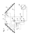
- FIG. 1 shows a circuit diagram of a solar system according to the invention.
- the solar system consists of a first solar collector 1 which is aligned on the west side and a second solar collector 2, which is aligned on the east side.
- the solar collectors 1, 2 are supplied via a common main supply line 3, which branches into two Einzelzuschreibtechnischen 4, 5, leading to the individual solar collectors 1, 2.
- two individual return lines 6, 7 lead into a main return line 8.
- the heat transfer medium is conveyed through a arranged in the main supply line 3 speed-controlled pump 9 to the individual solar collectors 1, 2 and passed through a consumer 10, which is shown here generally as a heat exchanger.
- a consumer 10 generally refers to any component designed to utilize solar heat, such as a heater buffer, a water heater, the evaporator portion of a heat pump, or the like.
- the temperature of the heat transfer medium is measured at the collector output or in the individual return lines 6, 7 by first temperature sensors 11, 12. Another temperature sensor 13 is in the main return line 8 and yet another temperature sensor 14 is provided in the main supply line 3.
- these temperature sensors 11, 12, 13, 14 are connected to a control device 16, which controls the pump 9 and a distribution valve 17, which regulates the flow in the two individual supply lines 4, 5.
- This distribution valve 17 is designed as a mixing valve with a control range of 0% to 100%.
- the distribution valve 17 is continuously regulated and has a 3-point control with 24 V or 230 V.
- the present invention makes it possible to optimally operate a solar system with little effort, even if individual solar collectors 1, 2 are applied differently.
Landscapes
- Engineering & Computer Science (AREA)
- General Engineering & Computer Science (AREA)
- Thermal Sciences (AREA)
- Chemical & Material Sciences (AREA)
- Combustion & Propulsion (AREA)
- Mechanical Engineering (AREA)
- Physics & Mathematics (AREA)
- Life Sciences & Earth Sciences (AREA)
- Sustainable Development (AREA)
- Sustainable Energy (AREA)
- Other Air-Conditioning Systems (AREA)
- Engine Equipment That Uses Special Cycles (AREA)
- Steam Or Hot-Water Central Heating Systems (AREA)
Description
- Die Erfindung betrifft eine Solaranlage mit mindestens zwei Solarkollektoren unterschiedlicher Exposition, einem Verbraucher, einer Hauptzufuhrleitung, die sich in Einzelzufuhrleitungen zu den Solarkollektoren verzweigt und einer Hauptrückführleitung, in die Einzelrückführleitungen von den Solarkollektoren münden, mit einem Verteilventil, das an der Verzweigung der Hauptzufuhrleitung in die Einzelzufuhrleitungen oder an der Verzweigung der Hauptrückführleitung in die Einzelrückführleitungen angeordnet ist, und mit einer Pumpe zur Förderung eines Wärmeträgermediums.
- Mehrere in Serie geschaltete Solarkollektoren werden zur Vereinfachung in der Folge als einzelner Solarkollektor angesehen.
- Grundsätzlich wird bei der Konzeption von Solaranlagen mit mehreren Solarkollektoren versucht, diese so anzuordnen, dass die Exposition möglichst günstig und gleich ist, wie dies beispielsweise bei Anordnung in gleicher Ausrichtung auf einem südseitigen Dach der Fall ist. In einem solchen Fall können die Solarkollektoren ohne weitere Maßnahmen von einem Wärmeträgermedium parallel oder in Serie angeströmt werden.
- In manchen Fällen ist jedoch eine solche optimale Anordnung nicht möglich und einzelne Solarkollektoren weisen eine unterschiedliche Exposition auf. Das häufigste Beispiel einer solchen Situation ist die Installation einer Solaranlage auf einem Gebäude, dessen Dach einen First in Nord-Süd Richtung aufweist. Um eine über den Tagesablauf möglichst gut verteilten Ertrag zu erreichen, werden hier die Solarkollektoren teilweise am ostseitigen Dachabschnitt und teilweise am westseitigen Dachabschnitt befestigt. Es ist offensichtlich, dass eine gleichmäßige Durchströmung der Solarkollektoren ein suboptimales Ergebnis erbringt, da am Morgen die westseitigen Solarkollektoren nicht nur keinen Beitrag zur Erwärmung des Wärmeträgermediums liefern können, sondern auch noch Wärmeverluste auftreten können. In Verlauf des Vormittags werden auch die westseitigen Solarkollektoren bestrahlt, aber in einem ungünstigeren Winkel, und eine gleichmäßige Durchströmung führt letztlich dazu, dass wenig erwärmtes Wärmeträgermedium aus diesen Solarkollektoren dem heißen Wärmeträgermedium aus den anderen Kollektoren zugemischt wird, was den Gesamtwirkungsgrad verschlechtert.
- Am Nachmittag und Abend wiederum sind umgekehrt die ostseitigen Solarkollektoren weniger oder nicht in der Lage, zur Wärmegewinnung beizutragen und sind somit Ursache für Verluste.
- Es sind aber auch noch andere Beispiele unterschiedlicher Exposition möglich, wie etwa wenn einzelne Gruppen von Solarkollektoren unterschiedliche hydraulische Eigenschaften aufweisen oder zeitweise in unterschiedlicher Weise abgeschattet werden.
- Um solchen Bedingungen Rechnung zu tragen, ist bereits vorgeschlagen worden, die Solarkollektoren selektiv ab- und zuzuschalten, indem durch ein Umschaltventil der Zufluss gesteuert wird. Solche früheren Lösungen sind beispielsweise in der
JP 2003262405 A US 4,184,481 A beschrieben. Die Temperatur des Wärmeträgermediums schwankt dabei ständig entsprechend dem Ein- und Ausschalten einzelner Strömungswege, so dass eine effiziente Regelung und eine Optimierung des Wärmeertrags nicht möglich sind. - Eine ähnliche Lösung ist in der
DE 195 33 475 A offenbart. Auch hier werden einzelne Kollektoren temperaturabhängig zu- oder abgeschaltet. - Um diese Nachteile zu vermeiden sind Solaranlagen bekannt geworden, bei denen die einzelnen Solarkollektoren bzw. Gruppen von Solarkollektoren getrennt voneinander durch eigene Zufuhr- und Abführleitungen versorgt werden. Jeder der Kreisläufe weist eine eigene, separat gesteuerte Pumpe auf, um der unterschiedlichen Exposition Rechnung zu tragen. Eine solche Lösung ist nicht nur apparativ aufwendig, sondern weist auch eine Reihe von Nachteilen auf. Konzeptbedingt sind beispielsweise drehzahlgeregelte Pumpen nur ab einem bestimmten Mindestdurchsatz betreibbar, der je nach Auslegung bei etwa 30% liegt. Damit können die weniger bestrahlen Solarkollektoren nur ganz abgeschaltet werden oder mit einer Mindestdurchflussmenge betrieben werden. Wenn nun die Sonneneinstrahlung nicht ausreicht, um eine entsprechende Erwärmung des Wärmeträgermediums bei diesem Mindestdurchsatz zu gewährleisten, dann treten die oben beschrieben Nachteile auf. Mit anderen Worten kann ein solches System Unterschiede in der Exposition einzelner Solarkollektoren nur dann ausgleichen, wenn diese nicht zu groß sind. Dieses Problem verschärft sich, wenn die Solaranlage in Verbindung mit einer Wärmepumpe betrieben wird, so dass das Wärmeträgermedium je nach Betriebszustand auch auf sehr niedrige Temperaturen abgekühlt werden kann und dann eine hohe Viskosität aufweist. Dies schränkt den Regelbereich der Pumpen unter Umständen auf weniger als 50% ein.
- Aufgabe der Erfindung ist es, diese Nachteile zu vermeiden und eine Lösung anzugeben, die einen einfachen Aufbau aufweist und einen optimalen Wirkungsgrad auch dann aufweist, wenn die Sonneneinstrahlung auf die einzelnen Solarkollektoren stark unterschiedlich ist. Eine weitere Aufgabe der Erfindung ist es, ein verbessertes Regelungsverfahren für solche Anlagen anzugeben.
- Erfindungsgemäß werden diese Aufgaben dadurch gelöst, dass das Verteilventil als Mischventil ausgebildet ist. Als Mischventil wird allgemein ein Ventil mit einem Hauptanschluss verstanden, von dem der Durchfluss stufenlos auf zwei Zweiganschlüsse aufteilbar ist. Solche Ventile werden beispielsweise in der Heizungstechnik dazu eingesetzt, durch Mischung von kaltem Medium und heißem Medium ein Medium mit genau vorgegebener Temperatur herzustellen.
- Im Rahmen der vorlegenden Erfindung weisen die einzelnen Teilströme am Mischventil jedoch im Idealfall die gleiche Temperatur auf, da nur die Volumenströme entsprechend beeinflusst werden.
- Wichtig ist es im Rahmen der Erfindung, dass die Durchströmgeschwindigkeit des Wärmeträgermediums durch die Solarkollektoren in einem weiten Bereich von nahezu Null auf einen durch die Auslegung vorgegebenen Maximalwert regelbar ist. Dadurch können auch große Unterschiede zwischen den einzelnen Kollektoren ausgeglichen werden.
- Ein Vorteil der vorliegenden Erfindung gegenüber Anlagen mit zwei Pumpen besteht auch darin, dass bei herkömmlicher Anordnung der Solaranlage mit den Solarkollektoren am Dach und den übrigen Komponenten im Keller eines Gebäudes nicht drei sondern nur zwei Steigleitungen benötigt werden, da das Mischventil in unmittelbarer Nähe der Solarkollektoren angeordnet werden kann. Grundsätzlich ist es möglich, das Verteilventil sowohl im Vorlauf als auch im Rücklauf anzuordnen, es ist allerdings bevorzugt, wenn das Verteilventil an der Verzweigung der Hauptzufuhrleitung in die Einzelzufuhrleitungen in unmittelbarer Nähe der Solarkollektoren angeordnet ist. Auf diese Weise kann die thermische Belastung des Verteilventils vergleichsweise gering gehalten werden.
- Von besonderem Vorteil ist es, wenn in den Einzelrückführleitungen bzw. in den Solarkollektoren selbst jeweils erste Temperatursensoren angeordnet sind. Dabei ist es besonders günstig, wenn in der Hauptrückführleitung ein weiterer Temperatursensor angeordnet ist. Die erfindungsgemäße Anlage wird einerseits insgesamt geregelt, indem die Drehzahl der Pumpe an das verfügbare Wärmeangebot angepasst wird. Andererseits wird der Durchfluss durch die Solarkollektoren durch Regelung des Mischventils so aufgeteilt, dass die Temperatur des Wärmeträgermediums stromabwärts der Solarkollektoren möglichst gleich ist. An sich ist es möglich, beide Regelungen durchzuführen wenn die Temperatur des Wärmeträgermediums am Kollektorausgang bekannt ist. Dabei beeinflussen allerdings Regelabweichungen beim Mischventil die Regelung der Pumpe da die Gesamttemperatur des Wärmeträgermediums nach Vermischung aus den beiden gemessenen Einzeltemperaturen berechnet werden muss. Dies kann zu Fehlern führen, da die einzelnen Volumenströme nicht direkt bekannt sind und allenfalls aus der jeweiligen Stellung des Mischventils rückgeschlossen werden können. Überdies ermöglicht die mehrfache Temperaturmessung eine verbesserte Fehlerkontrolle. Überdies wird eine erhöhte Genauigkeit der Regelung der Anlage erreicht, wenn die zusätzlichen Temperatursensoren in direkter Nähe zum Verbraucher angeordnet sind, da Wärmeverluste in den Steigleitungen so keine Verzerrung bewirken.
- Ein besonderer Vorteil der erfindungsgemäßen Lösung besteht auch darin, dass es bei der Auslegung der Solaranlage nicht mehr erforderlich ist, besonderes Augenmerk auf die hydraulische Gestaltung der parallel geschalteten Solarkollektoren zu legen. Es ist sogar möglich, unterschiedlich große Kollektorfelder ohne besondere Maßnahmen zusammenzuschalten, wenn beispielsweise ost- und westseitig unterschiedliche Platzverhältnisse vorliegen. Durch die erfindungsgemäße Lösung werden diese Unterschiede automatisch berücksichtigt und ausgeglichen, indem die Durchströmung automatisch angepasst wird. Auch Dächer mit unterschiedlichen Dachneigungen können so ohne besondere Maßnahmen mit Solarkollektoren versehen werden, ohne den Anlagenwirkungsgrad zu beeinträchtigen.
- Ein besonders hoher Wirkungsgrad kann erreicht werden, wenn die Pumpe als drehzahlgeregelte Pumpe ausgebildet ist, die in der Hauptzufuhrleitung angeordnet ist. Dadurch ist es möglich die Verluste an der Pumpe zu minimieren und eine besonders feine Regelung zu realisieren.
- Weiterhin betrifft die Erfindung ein Verfahren zur Regelung einer Solaranlage mit mindestens zwei Solarkollektoren unterschiedlicher Exposition, die über eine gemeinsame Pumpe mit Wärmeträgermedium versorgt werden.
- Dieses Verfahren sieht erfindungsgemäß vor, dass die Temperatur des Wärmeträgermediums stromabwärts der Solarkollektoren durch Aufteilung des Volumenstroms des Wärmeträgermediums auf einen einheitlichen Wert geregelt wird. Insbesondere ist diese Regelung dabei so aufgebaut, dass ein erster Regler ein Mischventil ansteuert, das den Durchfluss des Wärmeträgermediums durch die Solarkollektoren aufteilt, um die Temperaturdifferenz stromabwärts der Solarkollektoren so gering wie möglich zu machen. Eine solche Regelung ist besonders einfach, da die beiden Regelkreise weitestgehend voneinander entkoppelt sind und getrennt voneinander ausgelegt und getestet werden können. In der Praxis sind die beiden Regler zumeist als unterschiedliche Softwareabschnitte auf dem selben Steuergerät implementiert, was aber an der logischen Unabhängigkeit nichts ändert.
- Ein besonders hoher Wirkungsgrad kann erreicht werden, wenn unabhängig von der Regelung der Temperaturdifferenz eine weitere Regelung der Pumpe erfolgt, die auf Maximierung des Wärmeertrags ausgelegt ist. Der Gesamtertrag einer Solaranlage hängt wesentlich von der Durchströmung der Solarkollektoren ab. Ein maximaler Volumenstrom des Wärmeträgermediums senkt die Temperatur des Wärmeträgermediums am Solarkollektor und bewirkt eine Verringerung der Abstrahlverluste, es ist aber bei mäßiger Sonneneinstrahlung unter Umständen nicht mehr möglich, die Wärme in gewünschter Weise an die Verbraucher abzugeben, da das Temperaturniveau zu niedrig ist. Bei Anlagen mit Wärmepumpen muss diese mehr und mit schlechterer Leistungszahl arbeiten. Unter Berücksichtigung dieser Faktoren kann eine auf maximalen Wärmeertrag abzielende Regelung realisiert werden, die im Prinzip auf einem Modell der Anlage aufbaut und selbstlernend ausgeführt sein kann. Zusätzlich kann man bei der Regelung auf eine Minimierung des Stromverbrauchs abzielen, da bei modernen Hochleistungsanlagen auch die an sich geringe Energiemenge zum Antrieb der Pumpe berücksichtigt wird.
- In der Folge wird die vorliegende Erfindung anhand des in der Figur dargestellten Ausführungsbeispiels näher erläutert. Die Figur zeigt ein Schaltungsdiagramm einer erfindungsgemäßen Solaranlage.
- Die Solaranlage besteht aus einem ersten Solarkollektor 1 der westseitig ausgerichtet ist und einem zweiten Solarkollektor 2, der ostseitig ausgerichtet ist. Die Solarkollektoren 1, 2 werden über eine gemeinsame Hauptzufuhrleitung 3 versorgt, die sich in zwei Einzelzuführleitungen 4, 5 verzweigt, die zu den einzelnen Solarkollektoren 1, 2 führen. In analoger Weise münden zwei Einzelrückführleitungen 6, 7 in eine Hauptrückführleitung 8.
- Das Wärmeträgermedium wird durch eine in der Hauptzufuhrleitung 3 angeordnete drehzahlgeregelte Pumpe 9 zu den einzelnen Solarkollektoren 1, 2 gefördert und durch einen Verbraucher 10 geleitet, der hier allgemein als Wärmetauscher dargestellt ist. Dieser Ausdruck "Verbraucher" 10 steht hier allgemein für jede Komponente, die zur Nutzung der Solarwärme ausgebildet ist, wie etwa einen Heizungspuffer, ein Gerät zur Warmwasserbereitung, den Verdampferteil einer Wärmepumpe oder dgl.
- Die Temperatur des Wärmeträgermediums wird am Kollektorausgang bzw. in den Einzelrückführleitungen 6, 7 durch erste Temperatursensoren 11, 12 gemessen. Ein weiterer Temperatursensor 13 ist in der Hauptrückführleitung 8 und noch ein weiterer Temperatursensor 14 ist in der Hauptzufuhrleitung 3 vorgesehen.
- Über diverse Steuerleitungen 15 stehen diese Temperatursensoren 11, 12, 13, 14 mit einer Steuerungseinrichtung 16 in Verbindung, die die Pumpe 9 und ein Verteilventil 17 ansteuert, das den Durchfluss in den zwei Einzelzuführleitungen 4, 5 regelt. Dieses Verteilventil 17 ist als Mischventil mit einem Regelbereich von 0% bis 100% ausgeführt. Das Verteilventil 17 ist stetig geregelt und weist eine 3-Punkt-Ansteuerung mit 24 V oder 230 V auf.
- Die vorliegende Erfindung ermöglicht es, eine Solaranlage mit geringem Aufwand optimal zu betreiben, auch wenn einzelne Solarkollektoren 1, 2 unterschiedlich beaufschlagt werden.
Claims (14)
- Solaranlage mit mindestens zwei Solarkollektoren (1, 2) unterschiedlicher Exposition, einem Verbraucher (10), einer Hauptzufuhrleitung (3), die sich in Einzelzufuhrleitungen (4, 5) zu den Solarkollektoren (1, 2) verzweigt und einer Hauptrückführleitung (8), in die Einzelrückführleitungen (6, 7) von den Solarkollektoren (1, 2) münden, mit einem Verteilventil (17), das an der Verzweigung der Hauptzufuhrleitung (3) in die Einzelzufuhrleitungen (4, 5) oder an der Verzweigung der Hauptrückführleitung (8) in die Einzelrückführleitungen (6, 7) angeordnet ist, und mit einer Pumpe (9) zur Förderung eines Wärmeträgermediums, dadurch gekennzeichnet, dass das Verteilventil (17) als Mischventil ausgebildet ist.
- Solaranlage nach Anspruch 1, dadurch gekennzeichnet, dass das Verteilventil (17) an der Verzweigung der Hauptzufuhrleitung (3) in die Einzelzufuhrleitungen (4, 5) in unmittelbarer Nähe der Solarkollektoren (1, 2) angeordnet ist.
- Solaranlage nach einem der Ansprüche 1 oder 2, dadurch gekennzeichnet, dass in den Einzelrückführleitungen (6, 7) jeweils erste Temperatursensoren (11, 12) angeordnet sind.
- Solaranlage nach einem der Ansprüche 1 bis 3, dadurch gekennzeichnet, dass in der Hauptrückführleitung (8) ein weiterer Temperatursensor (13) angeordnet ist.
- Solaranlage nach Anspruch 4, dadurch gekennzeichnet, dass der weitere Temperatursensor (13) unmittelbar beim Verbraucher (10) angeordnet ist.
- Solaranlage nach einem der Ansprüche 1 bis 5, dadurch gekennzeichnet, dass das Verteilventil (17) einen stufenlosen Regelbereich von 0% bis 100% für jede der Zweigleitungen (4, 5; 6, 7) aufweist.
- Solaranlage nach einem der Ansprüche 1 bis 6, dadurch gekennzeichnet, dass die Pumpe (9) als drehzahlgeregelte Pumpe ausgebildet ist, die in der Hauptzufuhrleitung (3) angeordnet ist.
- Solaranlage nach einem der Ansprüche 1 bis 7, dadurch gekennzeichnet, dass die Solarkollektoren (1, 2) in unterschiedliche Himmelsrichtungen ausgerichtet sind.
- Solaranlage nach einem der Ansprüche 1 bis 7, dadurch gekennzeichnet, dass die Solarkollektoren (1, 2) unterschiedliche Neigungen aufweisen.
- Solaranlage nach einem der Ansprüche 1 bis 9, dadurch gekennzeichnet, dass das Verteilventil (17) als stetig geregeltes Ventil ausgebildet ist.
- Verfahren zur Regelung einer Solaranlage mit mindestens zwei Solarkollektoren (1, 2) unterschiedlicher Exposition, die über eine gemeinsame Pumpe (9) mit Wärmeträgermedium versorgt werden, dadurch gekennzeichnet, dass die Temperatur des Wärmeträgermediums stromabwärts der Solarkollektoren (1, 2) durch Aufteilung des Volumenstroms des Wärmeträgermediums auf einen einheitlichen Wert geregelt wird.
- Verfahren nach Anspruch 11, dadurch gekennzeichnet, dass ein erster Regler ein Mischventil (17) ansteuert, das den Durchfluss des Wärmeträgermediums durch die Solarkollektoren (1, 2) aufteilt, um die Temperaturdifferenz stromabwärts der Solarkollektoren (1, 2) so gering wie möglich zu machen.
- Verfahren nach einem der Ansprüche 11 oder 12, dadurch gekennzeichnet, dass unabhängig von der Regelung der Temperaturdifferenz eine weitere Regelung der Pumpe (9) erfolgt, die auf Maximierung des Wärmeertrags und/oder Minimierung des Stromverbrauchs ausgelegt ist.
- Verfahren nach Anspruch 13, dadurch gekennzeichnet, dass die weitere Regelung durch Einstellung der Drehzahl der Pumpe (9) durchgeführt wird.
Priority Applications (1)
| Application Number | Priority Date | Filing Date | Title |
|---|---|---|---|
| PL10728699T PL2459936T3 (pl) | 2009-07-29 | 2010-07-07 | Instalacja solarna z co najmniej dwoma kolektorami słonecznymi o różnej ekspozycji |
Applications Claiming Priority (2)
| Application Number | Priority Date | Filing Date | Title |
|---|---|---|---|
| AT0119009A AT508749A1 (de) | 2009-07-29 | 2009-07-29 | Solaranlage mit mindestens zwei solarkollektoren unterschiedlicher exposition |
| PCT/EP2010/059692 WO2011012411A2 (de) | 2009-07-29 | 2010-07-07 | Solaranlage mit mindestens zwei solarkollektoren unterschiedlicher exposition |
Publications (2)
| Publication Number | Publication Date |
|---|---|
| EP2459936A2 EP2459936A2 (de) | 2012-06-06 |
| EP2459936B1 true EP2459936B1 (de) | 2013-04-03 |
Family
ID=43529750
Family Applications (1)
| Application Number | Title | Priority Date | Filing Date |
|---|---|---|---|
| EP10728699A Not-in-force EP2459936B1 (de) | 2009-07-29 | 2010-07-07 | Solaranlage mit mindestens zwei solarkollektoren unterschiedlicher exposition |
Country Status (6)
| Country | Link |
|---|---|
| US (1) | US20120180782A1 (de) |
| EP (1) | EP2459936B1 (de) |
| AT (1) | AT508749A1 (de) |
| ES (1) | ES2414871T3 (de) |
| PL (1) | PL2459936T3 (de) |
| WO (1) | WO2011012411A2 (de) |
Family Cites Families (18)
| Publication number | Priority date | Publication date | Assignee | Title |
|---|---|---|---|---|
| US1658455A (en) * | 1926-03-13 | 1928-02-07 | Metzech Herman | Solar heater |
| US4184481A (en) * | 1977-08-01 | 1980-01-22 | August Tornquist | Directional self-supporting pyramid shaped hot water solar absorber |
| US4149525A (en) * | 1977-10-14 | 1979-04-17 | Prado David A | Solar collector |
| US4324228A (en) * | 1980-08-11 | 1982-04-13 | Paul Shippee | Solar heating apparatus |
| US4434786A (en) * | 1982-09-23 | 1984-03-06 | Lanciault Joseph A | Adjustable solar heat collector |
| US4771763A (en) * | 1983-02-14 | 1988-09-20 | Wetzel Enterprises, Inc. | Solar powered fluid heating system |
| US4615328A (en) * | 1983-02-14 | 1986-10-07 | Wetzel Enterprises, Inc. | Solar powered fluid heating system having an improved thermal collector assembly |
| US4964395A (en) * | 1986-11-20 | 1990-10-23 | Salgado Angel M | Apparatus and method for a solar radiation water heater |
| US4782816A (en) * | 1986-11-20 | 1988-11-08 | Salgado Angel M | Apparatus for a solar water heater |
| DE19533475B4 (de) * | 1995-09-12 | 2006-04-13 | Krecké, Edmond Dominique | Energieanlage für Gebäude |
| DE10245572B4 (de) * | 2002-03-26 | 2016-06-09 | Hg Baunach Gmbh & Co Kg | Heizungsanlage mit einem Mehrwegemischventil |
| JP2003262405A (ja) * | 2002-03-08 | 2003-09-19 | Noritz Corp | 太陽熱利用温水器 |
| CN1997859B (zh) * | 2004-04-23 | 2010-06-23 | Msc能量私人有限公司 | 采用多系统发电和水脱盐的结构 |
| DE102006017286B4 (de) * | 2006-04-12 | 2009-12-03 | Schneider, Franz, Dipl.-Ing. (Fh) | Schaltung zur Reduzierung der Rücklauftemperatur bei zwei Heizkreisen mit unterschiedlichen Temperaturniveaus |
| US20080216821A1 (en) * | 2007-03-05 | 2008-09-11 | Taco, Inc. | Solar heating systems with integrated circulator control |
| US7870855B2 (en) * | 2008-01-16 | 2011-01-18 | Flaherty B Michael | Solar heat collecting apparatus |
| US8047200B1 (en) * | 2009-11-19 | 2011-11-01 | Flaherty B Michael | Hybrid solar heating system |
| WO2013130350A1 (en) * | 2012-02-27 | 2013-09-06 | Yan Kunczynski | Direct flow solar collector |
-
2009
- 2009-07-29 AT AT0119009A patent/AT508749A1/de not_active Application Discontinuation
-
2010
- 2010-07-07 ES ES10728699T patent/ES2414871T3/es active Active
- 2010-07-07 WO PCT/EP2010/059692 patent/WO2011012411A2/de not_active Ceased
- 2010-07-07 EP EP10728699A patent/EP2459936B1/de not_active Not-in-force
- 2010-07-07 PL PL10728699T patent/PL2459936T3/pl unknown
- 2010-07-07 US US13/384,517 patent/US20120180782A1/en not_active Abandoned
Also Published As
| Publication number | Publication date |
|---|---|
| WO2011012411A2 (de) | 2011-02-03 |
| PL2459936T3 (pl) | 2013-10-31 |
| ES2414871T3 (es) | 2013-07-23 |
| US20120180782A1 (en) | 2012-07-19 |
| WO2011012411A3 (de) | 2011-10-27 |
| AT508749A1 (de) | 2011-03-15 |
| EP2459936A2 (de) | 2012-06-06 |
Similar Documents
| Publication | Publication Date | Title |
|---|---|---|
| DE10312825B4 (de) | Verfahren zum Einstellen mehrerer parallel geschalteter Wärmetauscher | |
| EP2154436B1 (de) | Verfahren und Vorrichtung zur Wärmenutzung | |
| DE102006045034A1 (de) | Wassergekühlte Konstanttemperatur-Flüssigkeitszirkuliervorrichtung und Verfahren zur Steuerung der Temperatur der zirkulierenden Flüssigkeit | |
| EP2426420B1 (de) | Warmwasserbereitungsanlage und Verfahren zum Betreiben einer Warmwasserbereitungsanlage | |
| EP2087290A1 (de) | Heiz- oder kühlanlage | |
| EP1357336B1 (de) | Anlage zur Versorgung von Verbrauchern mit Wärmeenergie unterschiedlicher Energieniveaus | |
| EP2000742B1 (de) | Mischeinrichtung zur Einstellung der Warmwassertemperatur | |
| AT406081B (de) | Heizanlage | |
| EP1752852A2 (de) | Verfahren zur Regelung der Temperatur des Mediums eines Heiz- und/oder Kühlsystems | |
| EP1704378B1 (de) | Mehrstufen-warmetauscheranordnung | |
| EP3431889A1 (de) | Versorgungskreis für ein wärmeträgermedium für einen verbraucher, industrieanlage und verfahren zum betreiben von solchen | |
| AT505065B1 (de) | Verfahren zur bereitstellung von thermischer energie | |
| EP2459936B1 (de) | Solaranlage mit mindestens zwei solarkollektoren unterschiedlicher exposition | |
| EP2413047B2 (de) | Brauchwassererwärmungseinheit | |
| DE10259279B3 (de) | Versorgungssystem für Heiz-oder Kühlwasser sowie Verfahren zum Betreiben desselben | |
| EP2413044B1 (de) | Brauchwassererwärmungseinheit | |
| WO2009074145A2 (de) | Verfahren zum steuern oder regeln einer heizungsanlage und heizanlage | |
| EP2442037B1 (de) | Verfahren zur Regelung einer Heizungsanlage | |
| AT526014A1 (de) | Verfahren zum Kühlen oder Heizen von Räumen | |
| DE10254889B4 (de) | Regeltechnische Lösung für eine Wassererwärmungsanlage | |
| DE102006023627B4 (de) | Solaranlage | |
| DE3019475A1 (de) | System zur waermegewinnung aus solar- bzw. umgebungsenergie | |
| EP2598805A2 (de) | Mischeinrichtung zur einstellung der warmwassertemperatur | |
| DE102011056796B4 (de) | Solarthermisches Kraftwerk und Verfahren zur Regelung des Wärmeträgermediummassenstroms | |
| AT405329B (de) | Wasserheizanlage mit einem primärwärmetauscher |
Legal Events
| Date | Code | Title | Description |
|---|---|---|---|
| PUAI | Public reference made under article 153(3) epc to a published international application that has entered the european phase |
Free format text: ORIGINAL CODE: 0009012 |
|
| 17P | Request for examination filed |
Effective date: 20120228 |
|
| AK | Designated contracting states |
Kind code of ref document: A2 Designated state(s): AL AT BE BG CH CY CZ DE DK EE ES FI FR GB GR HR HU IE IS IT LI LT LU LV MC MK MT NL NO PL PT RO SE SI SK SM TR |
|
| DAX | Request for extension of the european patent (deleted) | ||
| GRAP | Despatch of communication of intention to grant a patent |
Free format text: ORIGINAL CODE: EPIDOSNIGR1 |
|
| GRAS | Grant fee paid |
Free format text: ORIGINAL CODE: EPIDOSNIGR3 |
|
| GRAA | (expected) grant |
Free format text: ORIGINAL CODE: 0009210 |
|
| AK | Designated contracting states |
Kind code of ref document: B1 Designated state(s): AL AT BE BG CH CY CZ DE DK EE ES FI FR GB GR HR HU IE IS IT LI LT LU LV MC MK MT NL NO PL PT RO SE SI SK SM TR |
|
| REG | Reference to a national code |
Ref country code: GB Ref legal event code: FG4D Free format text: NOT ENGLISH |
|
| REG | Reference to a national code |
Ref country code: AT Ref legal event code: REF Ref document number: 604981 Country of ref document: AT Kind code of ref document: T Effective date: 20130415 Ref country code: CH Ref legal event code: EP |
|
| REG | Reference to a national code |
Ref country code: IE Ref legal event code: FG4D Free format text: LANGUAGE OF EP DOCUMENT: GERMAN |
|
| REG | Reference to a national code |
Ref country code: DE Ref legal event code: R096 Ref document number: 502010002874 Country of ref document: DE Effective date: 20130529 |
|
| REG | Reference to a national code |
Ref country code: ES Ref legal event code: FG2A Ref document number: 2414871 Country of ref document: ES Kind code of ref document: T3 Effective date: 20130723 |
|
| PG25 | Lapsed in a contracting state [announced via postgrant information from national office to epo] |
Ref country code: SI Free format text: LAPSE BECAUSE OF FAILURE TO SUBMIT A TRANSLATION OF THE DESCRIPTION OR TO PAY THE FEE WITHIN THE PRESCRIBED TIME-LIMIT Effective date: 20130403 |
|
| REG | Reference to a national code |
Ref country code: NL Ref legal event code: VDEP Effective date: 20130403 |
|
| REG | Reference to a national code |
Ref country code: LT Ref legal event code: MG4D |
|
| PG25 | Lapsed in a contracting state [announced via postgrant information from national office to epo] |
Ref country code: FI Free format text: LAPSE BECAUSE OF FAILURE TO SUBMIT A TRANSLATION OF THE DESCRIPTION OR TO PAY THE FEE WITHIN THE PRESCRIBED TIME-LIMIT Effective date: 20130403 Ref country code: LT Free format text: LAPSE BECAUSE OF FAILURE TO SUBMIT A TRANSLATION OF THE DESCRIPTION OR TO PAY THE FEE WITHIN THE PRESCRIBED TIME-LIMIT Effective date: 20130403 Ref country code: IS Free format text: LAPSE BECAUSE OF FAILURE TO SUBMIT A TRANSLATION OF THE DESCRIPTION OR TO PAY THE FEE WITHIN THE PRESCRIBED TIME-LIMIT Effective date: 20130803 Ref country code: NO Free format text: LAPSE BECAUSE OF FAILURE TO SUBMIT A TRANSLATION OF THE DESCRIPTION OR TO PAY THE FEE WITHIN THE PRESCRIBED TIME-LIMIT Effective date: 20130703 Ref country code: PT Free format text: LAPSE BECAUSE OF FAILURE TO SUBMIT A TRANSLATION OF THE DESCRIPTION OR TO PAY THE FEE WITHIN THE PRESCRIBED TIME-LIMIT Effective date: 20130805 Ref country code: SE Free format text: LAPSE BECAUSE OF FAILURE TO SUBMIT A TRANSLATION OF THE DESCRIPTION OR TO PAY THE FEE WITHIN THE PRESCRIBED TIME-LIMIT Effective date: 20130403 Ref country code: NL Free format text: LAPSE BECAUSE OF FAILURE TO SUBMIT A TRANSLATION OF THE DESCRIPTION OR TO PAY THE FEE WITHIN THE PRESCRIBED TIME-LIMIT Effective date: 20130403 Ref country code: GR Free format text: LAPSE BECAUSE OF FAILURE TO SUBMIT A TRANSLATION OF THE DESCRIPTION OR TO PAY THE FEE WITHIN THE PRESCRIBED TIME-LIMIT Effective date: 20130704 |
|
| REG | Reference to a national code |
Ref country code: PL Ref legal event code: T3 |
|
| PG25 | Lapsed in a contracting state [announced via postgrant information from national office to epo] |
Ref country code: LV Free format text: LAPSE BECAUSE OF FAILURE TO SUBMIT A TRANSLATION OF THE DESCRIPTION OR TO PAY THE FEE WITHIN THE PRESCRIBED TIME-LIMIT Effective date: 20130403 Ref country code: HR Free format text: LAPSE BECAUSE OF FAILURE TO SUBMIT A TRANSLATION OF THE DESCRIPTION OR TO PAY THE FEE WITHIN THE PRESCRIBED TIME-LIMIT Effective date: 20130403 Ref country code: BG Free format text: LAPSE BECAUSE OF FAILURE TO SUBMIT A TRANSLATION OF THE DESCRIPTION OR TO PAY THE FEE WITHIN THE PRESCRIBED TIME-LIMIT Effective date: 20130703 Ref country code: CY Free format text: LAPSE BECAUSE OF FAILURE TO SUBMIT A TRANSLATION OF THE DESCRIPTION OR TO PAY THE FEE WITHIN THE PRESCRIBED TIME-LIMIT Effective date: 20130403 |
|
| PGFP | Annual fee paid to national office [announced via postgrant information from national office to epo] |
Ref country code: PL Payment date: 20130628 Year of fee payment: 4 |
|
| BERE | Be: lapsed |
Owner name: VKR HOLDING A/S Effective date: 20130731 |
|
| PG25 | Lapsed in a contracting state [announced via postgrant information from national office to epo] |
Ref country code: EE Free format text: LAPSE BECAUSE OF FAILURE TO SUBMIT A TRANSLATION OF THE DESCRIPTION OR TO PAY THE FEE WITHIN THE PRESCRIBED TIME-LIMIT Effective date: 20130403 Ref country code: SK Free format text: LAPSE BECAUSE OF FAILURE TO SUBMIT A TRANSLATION OF THE DESCRIPTION OR TO PAY THE FEE WITHIN THE PRESCRIBED TIME-LIMIT Effective date: 20130403 Ref country code: DK Free format text: LAPSE BECAUSE OF FAILURE TO SUBMIT A TRANSLATION OF THE DESCRIPTION OR TO PAY THE FEE WITHIN THE PRESCRIBED TIME-LIMIT Effective date: 20130403 Ref country code: CZ Free format text: LAPSE BECAUSE OF FAILURE TO SUBMIT A TRANSLATION OF THE DESCRIPTION OR TO PAY THE FEE WITHIN THE PRESCRIBED TIME-LIMIT Effective date: 20130403 |
|
| PLBE | No opposition filed within time limit |
Free format text: ORIGINAL CODE: 0009261 |
|
| STAA | Information on the status of an ep patent application or granted ep patent |
Free format text: STATUS: NO OPPOSITION FILED WITHIN TIME LIMIT |
|
| PG25 | Lapsed in a contracting state [announced via postgrant information from national office to epo] |
Ref country code: MC Free format text: LAPSE BECAUSE OF FAILURE TO SUBMIT A TRANSLATION OF THE DESCRIPTION OR TO PAY THE FEE WITHIN THE PRESCRIBED TIME-LIMIT Effective date: 20130403 Ref country code: RO Free format text: LAPSE BECAUSE OF FAILURE TO SUBMIT A TRANSLATION OF THE DESCRIPTION OR TO PAY THE FEE WITHIN THE PRESCRIBED TIME-LIMIT Effective date: 20130403 |
|
| 26N | No opposition filed |
Effective date: 20140106 |
|
| REG | Reference to a national code |
Ref country code: DE Ref legal event code: R097 Ref document number: 502010002874 Country of ref document: DE Effective date: 20140106 |
|
| REG | Reference to a national code |
Ref country code: IE Ref legal event code: MM4A |
|
| PG25 | Lapsed in a contracting state [announced via postgrant information from national office to epo] |
Ref country code: BE Free format text: LAPSE BECAUSE OF NON-PAYMENT OF DUE FEES Effective date: 20130731 |
|
| PG25 | Lapsed in a contracting state [announced via postgrant information from national office to epo] |
Ref country code: IE Free format text: LAPSE BECAUSE OF NON-PAYMENT OF DUE FEES Effective date: 20130707 |
|
| PGFP | Annual fee paid to national office [announced via postgrant information from national office to epo] |
Ref country code: ES Payment date: 20140611 Year of fee payment: 5 |
|
| PGFP | Annual fee paid to national office [announced via postgrant information from national office to epo] |
Ref country code: DE Payment date: 20140702 Year of fee payment: 5 Ref country code: CH Payment date: 20140714 Year of fee payment: 5 |
|
| PGFP | Annual fee paid to national office [announced via postgrant information from national office to epo] |
Ref country code: GB Payment date: 20140702 Year of fee payment: 5 Ref country code: FR Payment date: 20140708 Year of fee payment: 5 |
|
| PGFP | Annual fee paid to national office [announced via postgrant information from national office to epo] |
Ref country code: IT Payment date: 20140711 Year of fee payment: 5 |
|
| PG25 | Lapsed in a contracting state [announced via postgrant information from national office to epo] |
Ref country code: SM Free format text: LAPSE BECAUSE OF FAILURE TO SUBMIT A TRANSLATION OF THE DESCRIPTION OR TO PAY THE FEE WITHIN THE PRESCRIBED TIME-LIMIT Effective date: 20130403 |
|
| PG25 | Lapsed in a contracting state [announced via postgrant information from national office to epo] |
Ref country code: MT Free format text: LAPSE BECAUSE OF FAILURE TO SUBMIT A TRANSLATION OF THE DESCRIPTION OR TO PAY THE FEE WITHIN THE PRESCRIBED TIME-LIMIT Effective date: 20130403 Ref country code: TR Free format text: LAPSE BECAUSE OF FAILURE TO SUBMIT A TRANSLATION OF THE DESCRIPTION OR TO PAY THE FEE WITHIN THE PRESCRIBED TIME-LIMIT Effective date: 20130403 |
|
| PG25 | Lapsed in a contracting state [announced via postgrant information from national office to epo] |
Ref country code: HU Free format text: LAPSE BECAUSE OF FAILURE TO SUBMIT A TRANSLATION OF THE DESCRIPTION OR TO PAY THE FEE WITHIN THE PRESCRIBED TIME-LIMIT; INVALID AB INITIO Effective date: 20100707 Ref country code: LU Free format text: LAPSE BECAUSE OF NON-PAYMENT OF DUE FEES Effective date: 20130707 Ref country code: MK Free format text: LAPSE BECAUSE OF FAILURE TO SUBMIT A TRANSLATION OF THE DESCRIPTION OR TO PAY THE FEE WITHIN THE PRESCRIBED TIME-LIMIT Effective date: 20130403 |
|
| REG | Reference to a national code |
Ref country code: PL Ref legal event code: LAPE |
|
| PG25 | Lapsed in a contracting state [announced via postgrant information from national office to epo] |
Ref country code: PL Free format text: LAPSE BECAUSE OF NON-PAYMENT OF DUE FEES Effective date: 20140707 |
|
| REG | Reference to a national code |
Ref country code: DE Ref legal event code: R119 Ref document number: 502010002874 Country of ref document: DE |
|
| REG | Reference to a national code |
Ref country code: CH Ref legal event code: PL |
|
| GBPC | Gb: european patent ceased through non-payment of renewal fee |
Effective date: 20150707 |
|
| PG25 | Lapsed in a contracting state [announced via postgrant information from national office to epo] |
Ref country code: IT Free format text: LAPSE BECAUSE OF NON-PAYMENT OF DUE FEES Effective date: 20150707 Ref country code: LI Free format text: LAPSE BECAUSE OF NON-PAYMENT OF DUE FEES Effective date: 20150731 Ref country code: GB Free format text: LAPSE BECAUSE OF NON-PAYMENT OF DUE FEES Effective date: 20150707 Ref country code: DE Free format text: LAPSE BECAUSE OF NON-PAYMENT OF DUE FEES Effective date: 20160202 Ref country code: CH Free format text: LAPSE BECAUSE OF NON-PAYMENT OF DUE FEES Effective date: 20150731 |
|
| REG | Reference to a national code |
Ref country code: FR Ref legal event code: ST Effective date: 20160331 |
|
| PG25 | Lapsed in a contracting state [announced via postgrant information from national office to epo] |
Ref country code: FR Free format text: LAPSE BECAUSE OF NON-PAYMENT OF DUE FEES Effective date: 20150731 |
|
| REG | Reference to a national code |
Ref country code: ES Ref legal event code: FD2A Effective date: 20160826 |
|
| REG | Reference to a national code |
Ref country code: AT Ref legal event code: MM01 Ref document number: 604981 Country of ref document: AT Kind code of ref document: T Effective date: 20150707 |
|
| PG25 | Lapsed in a contracting state [announced via postgrant information from national office to epo] |
Ref country code: ES Free format text: LAPSE BECAUSE OF NON-PAYMENT OF DUE FEES Effective date: 20150708 Ref country code: AT Free format text: LAPSE BECAUSE OF NON-PAYMENT OF DUE FEES Effective date: 20150707 |
|
| PG25 | Lapsed in a contracting state [announced via postgrant information from national office to epo] |
Ref country code: AL Free format text: LAPSE BECAUSE OF FAILURE TO SUBMIT A TRANSLATION OF THE DESCRIPTION OR TO PAY THE FEE WITHIN THE PRESCRIBED TIME-LIMIT Effective date: 20130403 |