EP2460410B1 - Dispositif et procédé pour laminer de la pâte - Google Patents
Dispositif et procédé pour laminer de la pâte Download PDFInfo
- Publication number
- EP2460410B1 EP2460410B1 EP20100193597 EP10193597A EP2460410B1 EP 2460410 B1 EP2460410 B1 EP 2460410B1 EP 20100193597 EP20100193597 EP 20100193597 EP 10193597 A EP10193597 A EP 10193597A EP 2460410 B1 EP2460410 B1 EP 2460410B1
- Authority
- EP
- European Patent Office
- Prior art keywords
- pair
- dough
- conveyor belts
- conveyor
- conveyor belt
- Prior art date
- Legal status (The legal status is an assumption and is not a legal conclusion. Google has not performed a legal analysis and makes no representation as to the accuracy of the status listed.)
- Active
Links
Images
Classifications
-
- A—HUMAN NECESSITIES
- A21—BAKING; EDIBLE DOUGHS
- A21C—MACHINES OR EQUIPMENT FOR MAKING OR PROCESSING DOUGHS; HANDLING BAKED ARTICLES MADE FROM DOUGH
- A21C3/00—Machines or apparatus for shaping batches of dough before subdivision
- A21C3/02—Dough-sheeters; Rolling-machines; Rolling-pins
- A21C3/022—Laminating or undulating a continuous dough sheet, e.g. by folding transversely or longitudinally onto a moving surface
Definitions
- the present invention relates to a method and device for lapping dough, in order to obtain a laminated dough, also referred to as puff paste.
- Devices for this purpose are also referred to as lappers or laminators, and they are well known in the art.
- the swinging device has been common practice to have a swinging device, with an upstream side that has an axis of rotation, and a downstream side that traverses the substrate alternatingly.
- the swinging device comprises a pair of guidances, such as plates, to guide a dough sheet in between them. This concept has proven to work for a limited width of a dough sheet. When the sheet becomes larger, friction between the sheet and the guidance prevents the dough from sliding over and away from the guidance. Improvements have been proposed.
- the US patent 3851088 shows an example such improved device, wherein the dough is delivered from a hopper to a swing member with conveyor belts instead of guidance plates, which swing member deposits the dough to a substrate.
- the substrate is curved, to minimise the distance over which the dough falls freely to the substrate.
- the above device fulfills a certain need, but it has the disadvantage that curving the substrate implies certain design difficulties, especially when the lapped dough is to be conveyed to a further location.
- This disadvantage was solved by a device disclosed in the CA patent application 365871 .
- This application discloses a swing member comprising two conveyor belts, for conveying dough enclosed in between them, hinged around a common axis of rotation at their upstream end, wherein each belt describes a path along four rollers, wherein the length of the path wherein the belts enclose the dough is adjustable, and controlled to minimise the distance over which the dough falls freely to the substrate.
- US 1 762 268 discloses a machine for rolling, folding and cross-rolling dough, wherein conveyor belts can be adjusted in accordance with the thickness of the sheet delivered from the rollers, to apply more or less pressure either at the receiving or delivering end of the conveyor belts.
- the invention thereto proposes a device for lapping dough, comprising a pair of mutually spaced conveyor belts, for conveying dough enclosed in between them, hinged around a common axis of rotation at their upstream end, a drive for swinging the pair of conveyor belts around the axis of rotation and a clamp, for applying an adjustable force between the mutually spaced conveyor belts.
- the conveyor belts may be endless conveyor belts, and the terms "upstream” and “downstream” are used here and below, referring to the direction of conveyance of the dough, i.e. upstream is the direction the dough comes from, and downstream is the direction the dough moves to, when the device is in (normal) use.
- the pair of conveyor belts may be arranged in a frame, that can be swung together with the belts.
- the space between the belts is adapted for the dough sheet to be conveyed in between them.
- the clamp may be embodied in its simplest form by an adjustable space between the conveyor belts, in order to use the device for various dough types with different viscosity, and to prevent dough from tearing, or with relatively fluid dough dough types.
- the device further comprises a third conveyor belt, arranged upstream of the mutually spaced belts for feeding dough to the belts, hinged around an axis of rotation at or toward its upstream end, and comprising drive means to swing the third conveyor belt around its axis of rotation.
- the third conveyor belt may comprise a first stretch, with a fixed direction of conveyance, and a second stretch, with a direction of conveyance that is at an adjustable angle with respect to the first stretch, the angle being adjustable around a horizontal axis.
- the third conveyor belt and the pair of conveyor belts thus form a pair of mutually movable legs, forming a V or an L like-shape.
- the angle between the legs is varied, i.e. stretched and subtracted alternatingly to arrange the dough on a substrate in the zig-zag manner.
- the downstream end of the third conveyor belt is arranged in the vicinity of the upstream end of the pair of conveyor belts, in order to transfer the dough smoothly.
- the clamp comprises at least one guidance plate arranged at the backside of at least one of the conveyor belts, the plate provided with an actuator for excerting a force on the conveyor belt, in the direction of the other conveyor belt.
- This embodiment has the advantage that the pressure or force can be regulated instantaneously, and in dependence of the conveyed dough.
- a sensor and a feedback loop may be present to adjust the force, or the force may be configured at a predetermined value, dependant on the type or amount of dough used.
- the guidance plate supports the conveyor belt and thus generates a pressure toward the dough and/or the other conveyor belt of the pair of belts.
- the clamp comprises two guidance plates, each plate arranged at the backside of a respective conveyor belt, and each plate provided with an actuator for excerting a force on the at least one belt, in the direction of the other belt.
- both guidance plates are moved toward each other, forcing the conveyor belts toward the dough sheet in between them.
- the guidance plates have a low friction coefficient, so that a toothed conveyor belts may be chosen for this purpose.
- the guidance plates are hinged at one of their ends, so that a force can be excerted by rotating the guidance plate around its axis of rotation, and with respective hinges at opposite sides, thus remaining parallel to each other during exertion of a force.
- the actuator can for example be embodied by a pneumatic cylinder. These actuators can be precisely controlled, and do not require greasing or other maintenance that may pollute the dough.
- the device comprises a fourth conveyor belt, arranged at the downstream end of the pair of conveyor belts, for receiving dough conveyed by the pair of conveyor belts, wherein the drive of the third conveyor belt and the drive of the pair of conveyor belts are configured to move the downstream end of the pair of conveyor belts alternatively away from and toward the upstream end of the third conveyor belt, for applying dough in a zig-zag manner on the fourth conveyor belt.
- Said fourth conveyor belt is most preferably arranged perpendicular to the direction of conveyance of the third conveyor belt.
- the drive means in the device according to the invention are configured to keep the downstream end of the pair of conveyor belts at a fixed distance from the fourth conveyor belt. This is to keep the distance over which the dough is freely falling constant. Since the pair of conveyor belts is in a preferred embodiment solely supported at its axis of rotation, the downstream end thereof thus "hovering".
- the drive of the pair of conveyor belts comprises a drive shaft, coupled to an actuator outside a dough conveyance area, for swinging the pair of conveyor belts.
- the actuator may be an electric motor or the like. This motor is arranged outside the working area of the conveyor belts as well, for keeping the working area of the machine clear, and free of lubricants and the like.
- a transmission may thereto comprise a toothed belt which is led aside the pair of conveyor belts.
- this width is between 60 and 200 cm, and in particular between 80 and 160 cm.
- the pair of conveyor belts is balanced for their horizontal support by a suspension.
- the suspension could for instance be a pneumatic suspension.
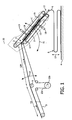
- Figure 1 shows the general principle of a device for lapping dough according to the present invention.
- the device comprises a pair of mutually spaced conveyor belts 1, 2, for conveying dough 6 enclosed in between them, hinged around a common axis of rotation 5 at their upstream end 7.
- a drive for swinging the pair of conveyor belts around the axis of rotation is not depicted.
- Figure 1 further shows a third conveyor 3 for delivering the dough to the pair of conveyors 1,2, and a fourth conveyor 4 for receiving the lapped dough 8.
- the upstream end 7 of the pair of conveyor belts 1, 2 is hinged at the downstream end of the third conveyor 3, which itself is hinged around an axis of rotation 9 toward its upstream end.
- the downstream end 12 of the pair of conveyor belts 1, 2 describes a path 13 with a constant distance to a fourth conveyor 4, on which the dough 6 is lapped 8.
- the path 13 may have a width of more than 0.6 meter, in particular even 1,20 meter or more, and in specific cases even 1,60 meter and higher.
- a clamp 14, 15 is depicted, for applying an adjustable force between the mutually spaced conveyor belts 1, 2.
- the clamp 14, 15 comprises two parts, 14, 15, which are arranged rotatable around respective axis of rotation 16, 17.
- forces 18, 19 can be applied to the parts 14, 15, which may for example be guidance plates.
- the forces 18, 19 are adjustable according to the invention, and may be coupled by control means (not depicted) to the viscosity of the dough. It may also be coupled to the rotational angle of the pair of conveyor belts 1, 2.
- the third conveyor 3 comprises an upstream (first) stretch, with a first fixed direction of conveyance, which is in the example given arranged slightly inclined, and a downstream (second) stretch 23a, which can be rotated around essentially horizontal axis of rotation 9.
- a driving roller 23b arranged in a loop 23c is also depicted.
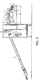
- Figure 2 shows a side view of an actual embodiment of a device according to the present invention. Besides the parts shown in figure 1 , figure 2 shows a connecting rod 21, for swinging the pair of conveyor belts 1, 2. The rod is operated by a motor 22, arranged outside the dough processing area, in order to avoid pollution of the dough.
- a pneumatic reservoir which is used for powering at least one pneumatic cylinder that counterbalances (the frame comporting) the pair of conveyor belts 1, 2 and the third conveyor belt.
- Other counter balancing means may be applied as well, in order to relieve the drives for the swinging movements.
- the width of the swing movement 24 of the downstream end of the pair of conveyor belts is 120 cm.
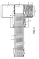
- Figure 3 shows a top view on the machine from figures 1 and 2 .
- the figure shows in particular how the dough sheet 6 is zig-zagged 8 on the fourth conveyor 4.
- Also visible in the figure is the connecting rod 21, which transfers the swinging movement of the pair of conveyor belts, from the motor placed outside 22 the dough processing area to a frame carrying the conveyor belts 1,2.
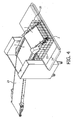
- FIG 4 shows a perspective view on the device shown in figures 2 and 3 .
- like reference numbers indicate like components.
- Clearly visible is the hovering or floating construction, providing a free space 25 around the pair of conveyor belts, which enables easy maintenance and cleaning.
- a cage 26 may be present to shield the moving parts from the device.
Landscapes
- Life Sciences & Earth Sciences (AREA)
- Engineering & Computer Science (AREA)
- Food Science & Technology (AREA)
- Structure Of Belt Conveyors (AREA)
- Manufacturing And Processing Devices For Dough (AREA)
Claims (14)
- Dispositif pour laminer de la pâte, comprenant :- une paire de courroies de transport (1, 2) mutuellement espacées, destinées à transporter de la pâte (6) prise en sandwich entre celles-ci, articulées autour d'un axe de rotation commun (5) au niveau de leur extrémité amont (7) ;- un système d'entraînement destiné à faire osciller la paire de courroies de transport autour de l'axe de rotation ;- une mâchoire (14, 15), destinée à appliquer une force ajustable entre les courroies de transport (1, 2) mutuellement espacées ;- une troisième courroie de transport (3),dans lequel l'extrémité amont (7) de la paire de courroies de transport (1, 2) est articulée au niveau de l'extrémité aval de la troisième courroie de transport (3).• disposée en amont des courroies (1, 2) mutuellement espacées et destinée à amener de la pâte aux courroies ;• articulée autour d'un axe de rotation (9) vers son extrémité amont ; et• comprenant des moyens d'entraînement pour faire osciller (10) la troisième courroie de transport (3) autour de son axe de rotation (9) ;
- Dispositif selon la revendication 1, dans lequel la mâchoire (14, 15) comprend au moins une plaque de guidage (14, 15) disposée à l'arrière d'au moins l'une des courroies de la paire de courroies de transport (1, 2) mutuellement espacées, la plaque étant dotée d'un actionneur destiné à exercer une force (18, 19) sur la courroie de transport (1, 2), dans la direction de l'autre courroie de transport (1,2).
- Dispositif selon la revendication 2, dans lequel la mâchoire (14, 15) comprend deux plaques de guidage (14, 15), chaque plaque étant disposée à l'arrière d'une courroie de transport (1, 2) respective, et chaque plaque étant dotée d'un actionneur destiné à exercer une force (18, 19) sur la ou les courroies, dans la direction de l'autre courroie.
- Dispositif selon la revendication 3, dans lequel les plaques de guidage (14, 15) sont articulées au niveau de côtés opposés, de sorte qu'elles restent parallèles l'une à l'autre lorsqu'une force est exercée.
- Dispositif selon la revendication 4, dans lequel l'actionneur prend la forme d'un vérin pneumatique.
- Dispositif selon l'une quelconque des revendications précédentes, comprenant :- une quatrième courroie de transport (4), disposée au niveau de l'extrémité aval de la paire de courroies de transport (1, 2), destinée à recevoir de la pâte acheminée par la paire de courroies de transport (1, 2), dans lequel- le système d'entraînement de la troisième courroie de transport (3) et le système d'entraînement de la paire de courroies de transport (1, 2) sont configurés pour déplacer l'extrémité aval de la paire de courroies de transport de façon à l'éloigner et à la rapprocher, en alternance, de l'extrémité amont de la troisième courroie de transport (3), afin de déposer de la pâte en zigzag sur la quatrième courroie de transport (4).
- Dispositif selon la revendication 6, dans lequel les moyens d'entraînement sont configurés pour maintenir l'extrémité aval de la paire de courroies de transport (1, 2) à une distance fixe de la quatrième courroie de transport (4).
- Dispositif selon l'une quelconque des revendications précédentes, dans lequel la paire de courroies de transport (1, 2) est uniquement supportée au niveau de son axe de rotation, de telle sorte que les courroies de transport soient accessibles à des fins d'entretien.
- Dispositif selon l'une quelconque des revendications précédentes, dans lequel le système d'entraînement destiné à faire osciller la paire de courroies de transport (1, 2) comprend un arbre d'entraînement, accouplé à un actionneur en dehors d'une zone d'acheminement de pâte.
- Dispositif selon l'une quelconque des revendications précédentes, dans lequel un système d'entraînement destiné à entraîner la paire de courroies de transport (1, 2) afin d'acheminer la pâte est situé en dehors d'une zone d'acheminement de pâte.
- Dispositif selon la revendication 10, dans lequel une transmission destinée à entraîner les courroies de transport afin d'acheminer la pâte comprend une courroie crantée.
- Dispositif selon l'une quelconque des revendications précédentes, dans lequel la paire de courroies de transport (1, 2) est équilibrée pour son support horizontal par une suspension.
- Dispositif selon la revendication 12, dans lequel la suspension est une suspension pneumatique.
- Procédé pour laminer de la pâte, comprenant :- acheminer de la pâte prise en sandwich entre une paire de courroies de transport (1, 2) mutuellement espacées,- faire osciller la paire de courroies de transport (1, 2) autour d'un axe de rotation (5) vers leur extrémité amont (7),- appliquer une force ajustable entre les courroies de transport (1, 2) mutuellement espacées, la pâte étant acheminée à la paire de courroies de transport (1, 2) mutuellement espacées par une troisième courroie de transport (3), et- faire osciller la troisième courroie de transport (3) autour d'un axe de rotation (9) vers son extrémité amont ;dans lequel l'extrémité amont (7) de la paire de courroies de transport (1, 2) est articulée au niveau de l'extrémité aval de la troisième courroie de transport (3).
Priority Applications (2)
| Application Number | Priority Date | Filing Date | Title |
|---|---|---|---|
| EP20100193597 EP2460410B1 (fr) | 2010-12-03 | 2010-12-03 | Dispositif et procédé pour laminer de la pâte |
| ES10193597.1T ES2494440T3 (es) | 2010-12-03 | 2010-12-03 | Dispositivo y método para laminación de masa |
Applications Claiming Priority (1)
| Application Number | Priority Date | Filing Date | Title |
|---|---|---|---|
| EP20100193597 EP2460410B1 (fr) | 2010-12-03 | 2010-12-03 | Dispositif et procédé pour laminer de la pâte |
Publications (2)
| Publication Number | Publication Date |
|---|---|
| EP2460410A1 EP2460410A1 (fr) | 2012-06-06 |
| EP2460410B1 true EP2460410B1 (fr) | 2014-07-23 |
Family
ID=43902834
Family Applications (1)
| Application Number | Title | Priority Date | Filing Date |
|---|---|---|---|
| EP20100193597 Active EP2460410B1 (fr) | 2010-12-03 | 2010-12-03 | Dispositif et procédé pour laminer de la pâte |
Country Status (2)
| Country | Link |
|---|---|
| EP (1) | EP2460410B1 (fr) |
| ES (1) | ES2494440T3 (fr) |
Cited By (4)
| Publication number | Priority date | Publication date | Assignee | Title |
|---|---|---|---|---|
| EP3078270A1 (fr) * | 2015-04-08 | 2016-10-12 | Fritsch GmbH | Dispositif de depot continu de pate repliee sur un moyen de transport |
| CN111282701A (zh) * | 2020-03-13 | 2020-06-16 | 广东东华园林绿化工程有限公司 | 一种园林垃圾回收粉碎系统及处理方法 |
| CN111387233A (zh) * | 2020-04-08 | 2020-07-10 | 蒋合奎 | 一种提高面团弹性的自动擀面设备 |
| DE102015017222B3 (de) | 2015-04-08 | 2023-03-30 | Fritsch Bakery Technologies GmbH & Co. KG | Vorrichtung zum kontinuierlichen gefalteten Ablegen von Teig auf einem Fördermittel |
Families Citing this family (3)
| Publication number | Priority date | Publication date | Assignee | Title |
|---|---|---|---|---|
| EP3479697B1 (fr) * | 2017-11-06 | 2020-10-21 | Minipan S.r.l. | Ensemble de traitement de pâte |
| WO2019230792A1 (fr) * | 2018-06-01 | 2019-12-05 | レオン自動機株式会社 | Dispositif d'allongement de pâte |
| EP3753413B1 (fr) | 2019-06-21 | 2023-10-11 | Radie B.V. | Dispositif de dépôt de pâte |
Family Cites Families (10)
| Publication number | Priority date | Publication date | Assignee | Title |
|---|---|---|---|---|
| US1482195A (en) * | 1924-01-29 | Dough working machine | ||
| CA365871A (fr) | 1937-05-04 | David Loose Kenneth | Machine a feuilleter et a laminer la pate | |
| US1762268A (en) * | 1920-02-24 | 1930-06-10 | Thomas L Green | Dough-sheeting machine |
| US2130097A (en) * | 1937-03-01 | 1938-09-13 | Loose Wiles Biscuit Co | Dough lapping machine |
| US2642013A (en) * | 1948-05-28 | 1953-06-16 | Interstate Bakeries Corp | Means for continuous shaping, feeding, and sheeting of dough |
| US3216374A (en) * | 1962-04-18 | 1965-11-09 | Briem Hengler & Cronemeyer K G | Automatic pastry dough processing device |
| US3698309A (en) | 1970-11-20 | 1972-10-17 | Baker Perkins Ltd | Dough laminating |
| US3851088A (en) | 1972-10-24 | 1974-11-26 | Nabisco Inc | Method for laminating sheet dough |
| US4004035A (en) * | 1975-07-28 | 1977-01-18 | Kellogg Company | Method and apparatus for producing lapped shredded food articles |
| IT1198565B (it) * | 1983-03-04 | 1988-12-21 | Ghiott Dolciaria Di Graziono T | Estrusore a nastri per impasto da biscotti e dolci in genere |
-
2010
- 2010-12-03 ES ES10193597.1T patent/ES2494440T3/es active Active
- 2010-12-03 EP EP20100193597 patent/EP2460410B1/fr active Active
Cited By (7)
| Publication number | Priority date | Publication date | Assignee | Title |
|---|---|---|---|---|
| EP3078270A1 (fr) * | 2015-04-08 | 2016-10-12 | Fritsch GmbH | Dispositif de depot continu de pate repliee sur un moyen de transport |
| DE102015004279A1 (de) | 2015-04-08 | 2016-10-13 | Fritsch Gmbh | Vorrichtung zum kontinuierlichen gefalteten Ablegen von Teig auf einem Fördermittel |
| DE102015004279B4 (de) * | 2015-04-08 | 2019-03-14 | Fritsch Gmbh | Vorrichtung zum kontinuierlichen gefalteten Ablegen von Teig auf einem Fördermittel |
| DE102015017222B3 (de) | 2015-04-08 | 2023-03-30 | Fritsch Bakery Technologies GmbH & Co. KG | Vorrichtung zum kontinuierlichen gefalteten Ablegen von Teig auf einem Fördermittel |
| CN111282701A (zh) * | 2020-03-13 | 2020-06-16 | 广东东华园林绿化工程有限公司 | 一种园林垃圾回收粉碎系统及处理方法 |
| CN111282701B (zh) * | 2020-03-13 | 2021-05-11 | 广东东华园林绿化工程有限公司 | 一种园林垃圾回收粉碎系统及处理方法 |
| CN111387233A (zh) * | 2020-04-08 | 2020-07-10 | 蒋合奎 | 一种提高面团弹性的自动擀面设备 |
Also Published As
| Publication number | Publication date |
|---|---|
| ES2494440T3 (es) | 2014-09-15 |
| EP2460410A1 (fr) | 2012-06-06 |
Similar Documents
| Publication | Publication Date | Title |
|---|---|---|
| EP2460410B1 (fr) | Dispositif et procédé pour laminer de la pâte | |
| JP5943400B2 (ja) | 二本ベルト式の受動ローラの箱回転装置 | |
| JP6861432B2 (ja) | 搬送装置及びコンベヤユニット | |
| JP2009001429A (ja) | 物品の流れの方向を転換するための装置 | |
| CN103596862B (zh) | 用于累积产品的装置 | |
| EP3294647B1 (fr) | Dispositif de désempilement et procédé de désempilement d'une masse d'articles | |
| JP2004522671A6 (ja) | 物品の流れの方向を転換するための装置 | |
| EP3085646A1 (fr) | Dispositif pour alimenter et renverser des produits dans une ligne d'alimentation | |
| JP2015527054A (ja) | スライドされた搬送ベルトを有するオーブン引き渡し装置 | |
| US10118765B2 (en) | Flexible-belt conveyor and methods of conveying | |
| NZ213212A (en) | Dough stretching: plurality of rollers reciprocate in straight line | |
| ITMI952018A1 (it) | Dispositivo deviatore per il trasporto di prodotti, in particolare prodotti grafici od editoriali | |
| AU2007240336A1 (en) | Dynamic conveyance device | |
| CN209062260U (zh) | 一种剪板机送料机构 | |
| CA2560186A1 (fr) | Dispositif de transport roulant | |
| CN211812113U (zh) | 用于转移产品的转移设备 | |
| JP7176726B2 (ja) | ローリング機構付き搬送装置 | |
| CN203975830U (zh) | 链条调节装置、链条牵引系统、悬挂链输送机及输送系统 | |
| KR20190014289A (ko) | 제품 그룹 포장 간격 조절장치 | |
| CN221241470U (zh) | 一种摆动折叠机 | |
| JP2008030860A (ja) | 分岐設備 | |
| CN216004265U (zh) | 一种纸箱输送装置 | |
| US4669720A (en) | Ejector unit for machines for handling signatures and similar articles, particularly for signature-stacking machines | |
| CN108974491A (zh) | 一种定位装置及装箱设备 | |
| JP2012193029A (ja) | 搬送装置 |
Legal Events
| Date | Code | Title | Description |
|---|---|---|---|
| PUAI | Public reference made under article 153(3) epc to a published international application that has entered the european phase |
Free format text: ORIGINAL CODE: 0009012 |
|
| AK | Designated contracting states |
Kind code of ref document: A1 Designated state(s): AL AT BE BG CH CY CZ DE DK EE ES FI FR GB GR HR HU IE IS IT LI LT LU LV MC MK MT NL NO PL PT RO RS SE SI SK SM TR |
|
| AX | Request for extension of the european patent |
Extension state: BA ME |
|
| 17P | Request for examination filed |
Effective date: 20121206 |
|
| 17Q | First examination report despatched |
Effective date: 20130110 |
|
| GRAP | Despatch of communication of intention to grant a patent |
Free format text: ORIGINAL CODE: EPIDOSNIGR1 |
|
| INTG | Intention to grant announced |
Effective date: 20140313 |
|
| GRAS | Grant fee paid |
Free format text: ORIGINAL CODE: EPIDOSNIGR3 |
|
| GRAA | (expected) grant |
Free format text: ORIGINAL CODE: 0009210 |
|
| AK | Designated contracting states |
Kind code of ref document: B1 Designated state(s): AL AT BE BG CH CY CZ DE DK EE ES FI FR GB GR HR HU IE IS IT LI LT LU LV MC MK MT NL NO PL PT RO RS SE SI SK SM TR |
|
| REG | Reference to a national code |
Ref country code: GB Ref legal event code: FG4D |
|
| REG | Reference to a national code |
Ref country code: CH Ref legal event code: EP |
|
| REG | Reference to a national code |
Ref country code: IE Ref legal event code: FG4D |
|
| REG | Reference to a national code |
Ref country code: AT Ref legal event code: REF Ref document number: 678322 Country of ref document: AT Kind code of ref document: T Effective date: 20140815 |
|
| REG | Reference to a national code |
Ref country code: DE Ref legal event code: R096 Ref document number: 602010017661 Country of ref document: DE Effective date: 20140904 |
|
| REG | Reference to a national code |
Ref country code: CH Ref legal event code: NV Representative=s name: R. A. EGLI AND CO. PATENTANWAELTE, CH Ref country code: ES Ref legal event code: FG2A Ref document number: 2494440 Country of ref document: ES Kind code of ref document: T3 Effective date: 20140915 |
|
| REG | Reference to a national code |
Ref country code: NL Ref legal event code: T3 |
|
| REG | Reference to a national code |
Ref country code: AT Ref legal event code: MK05 Ref document number: 678322 Country of ref document: AT Kind code of ref document: T Effective date: 20140723 |
|
| REG | Reference to a national code |
Ref country code: LT Ref legal event code: MG4D |
|
| PG25 | Lapsed in a contracting state [announced via postgrant information from national office to epo] |
Ref country code: BG Free format text: LAPSE BECAUSE OF FAILURE TO SUBMIT A TRANSLATION OF THE DESCRIPTION OR TO PAY THE FEE WITHIN THE PRESCRIBED TIME-LIMIT Effective date: 20141023 Ref country code: PT Free format text: LAPSE BECAUSE OF FAILURE TO SUBMIT A TRANSLATION OF THE DESCRIPTION OR TO PAY THE FEE WITHIN THE PRESCRIBED TIME-LIMIT Effective date: 20141124 Ref country code: FI Free format text: LAPSE BECAUSE OF FAILURE TO SUBMIT A TRANSLATION OF THE DESCRIPTION OR TO PAY THE FEE WITHIN THE PRESCRIBED TIME-LIMIT Effective date: 20140723 Ref country code: NO Free format text: LAPSE BECAUSE OF FAILURE TO SUBMIT A TRANSLATION OF THE DESCRIPTION OR TO PAY THE FEE WITHIN THE PRESCRIBED TIME-LIMIT Effective date: 20141023 Ref country code: LT Free format text: LAPSE BECAUSE OF FAILURE TO SUBMIT A TRANSLATION OF THE DESCRIPTION OR TO PAY THE FEE WITHIN THE PRESCRIBED TIME-LIMIT Effective date: 20140723 Ref country code: SE Free format text: LAPSE BECAUSE OF FAILURE TO SUBMIT A TRANSLATION OF THE DESCRIPTION OR TO PAY THE FEE WITHIN THE PRESCRIBED TIME-LIMIT Effective date: 20140723 Ref country code: GR Free format text: LAPSE BECAUSE OF FAILURE TO SUBMIT A TRANSLATION OF THE DESCRIPTION OR TO PAY THE FEE WITHIN THE PRESCRIBED TIME-LIMIT Effective date: 20141024 |
|
| PG25 | Lapsed in a contracting state [announced via postgrant information from national office to epo] |
Ref country code: HR Free format text: LAPSE BECAUSE OF FAILURE TO SUBMIT A TRANSLATION OF THE DESCRIPTION OR TO PAY THE FEE WITHIN THE PRESCRIBED TIME-LIMIT Effective date: 20140723 Ref country code: IS Free format text: LAPSE BECAUSE OF FAILURE TO SUBMIT A TRANSLATION OF THE DESCRIPTION OR TO PAY THE FEE WITHIN THE PRESCRIBED TIME-LIMIT Effective date: 20141123 Ref country code: PL Free format text: LAPSE BECAUSE OF FAILURE TO SUBMIT A TRANSLATION OF THE DESCRIPTION OR TO PAY THE FEE WITHIN THE PRESCRIBED TIME-LIMIT Effective date: 20140723 Ref country code: CY Free format text: LAPSE BECAUSE OF FAILURE TO SUBMIT A TRANSLATION OF THE DESCRIPTION OR TO PAY THE FEE WITHIN THE PRESCRIBED TIME-LIMIT Effective date: 20140723 Ref country code: LV Free format text: LAPSE BECAUSE OF FAILURE TO SUBMIT A TRANSLATION OF THE DESCRIPTION OR TO PAY THE FEE WITHIN THE PRESCRIBED TIME-LIMIT Effective date: 20140723 Ref country code: RS Free format text: LAPSE BECAUSE OF FAILURE TO SUBMIT A TRANSLATION OF THE DESCRIPTION OR TO PAY THE FEE WITHIN THE PRESCRIBED TIME-LIMIT Effective date: 20140723 Ref country code: AT Free format text: LAPSE BECAUSE OF FAILURE TO SUBMIT A TRANSLATION OF THE DESCRIPTION OR TO PAY THE FEE WITHIN THE PRESCRIBED TIME-LIMIT Effective date: 20140723 |
|
| REG | Reference to a national code |
Ref country code: DE Ref legal event code: R026 Ref document number: 602010017661 Country of ref document: DE |
|
| PG25 | Lapsed in a contracting state [announced via postgrant information from national office to epo] |
Ref country code: DK Free format text: LAPSE BECAUSE OF FAILURE TO SUBMIT A TRANSLATION OF THE DESCRIPTION OR TO PAY THE FEE WITHIN THE PRESCRIBED TIME-LIMIT Effective date: 20140723 Ref country code: RO Free format text: LAPSE BECAUSE OF FAILURE TO SUBMIT A TRANSLATION OF THE DESCRIPTION OR TO PAY THE FEE WITHIN THE PRESCRIBED TIME-LIMIT Effective date: 20140723 Ref country code: EE Free format text: LAPSE BECAUSE OF FAILURE TO SUBMIT A TRANSLATION OF THE DESCRIPTION OR TO PAY THE FEE WITHIN THE PRESCRIBED TIME-LIMIT Effective date: 20140723 Ref country code: CZ Free format text: LAPSE BECAUSE OF FAILURE TO SUBMIT A TRANSLATION OF THE DESCRIPTION OR TO PAY THE FEE WITHIN THE PRESCRIBED TIME-LIMIT Effective date: 20140723 Ref country code: SK Free format text: LAPSE BECAUSE OF FAILURE TO SUBMIT A TRANSLATION OF THE DESCRIPTION OR TO PAY THE FEE WITHIN THE PRESCRIBED TIME-LIMIT Effective date: 20140723 |
|
| PLBI | Opposition filed |
Free format text: ORIGINAL CODE: 0009260 |
|
| PLAX | Notice of opposition and request to file observation + time limit sent |
Free format text: ORIGINAL CODE: EPIDOSNOBS2 |
|
| 26 | Opposition filed |
Opponent name: FRITSCH GMBH Effective date: 20150423 |
|
| PG25 | Lapsed in a contracting state [announced via postgrant information from national office to epo] |
Ref country code: BE Free format text: LAPSE BECAUSE OF NON-PAYMENT OF DUE FEES Effective date: 20141231 |
|
| PG25 | Lapsed in a contracting state [announced via postgrant information from national office to epo] |
Ref country code: LU Free format text: LAPSE BECAUSE OF FAILURE TO SUBMIT A TRANSLATION OF THE DESCRIPTION OR TO PAY THE FEE WITHIN THE PRESCRIBED TIME-LIMIT Effective date: 20141203 |
|
| GBPC | Gb: european patent ceased through non-payment of renewal fee |
Effective date: 20141203 |
|
| PLBB | Reply of patent proprietor to notice(s) of opposition received |
Free format text: ORIGINAL CODE: EPIDOSNOBS3 |
|
| REG | Reference to a national code |
Ref country code: IE Ref legal event code: MM4A |
|
| PG25 | Lapsed in a contracting state [announced via postgrant information from national office to epo] |
Ref country code: GB Free format text: LAPSE BECAUSE OF NON-PAYMENT OF DUE FEES Effective date: 20141203 Ref country code: IE Free format text: LAPSE BECAUSE OF NON-PAYMENT OF DUE FEES Effective date: 20141203 |
|
| REG | Reference to a national code |
Ref country code: DE Ref legal event code: R082 Ref document number: 602010017661 Country of ref document: DE Representative=s name: BETTEN & RESCH PATENT- UND RECHTSANWAELTE PART, DE Ref country code: DE Ref legal event code: R081 Ref document number: 602010017661 Country of ref document: DE Owner name: RADIE B.V., NL Free format text: FORMER OWNER: RADEMAKER B.V., CULEMBORG, NL |
|
| PG25 | Lapsed in a contracting state [announced via postgrant information from national office to epo] |
Ref country code: SI Free format text: LAPSE BECAUSE OF FAILURE TO SUBMIT A TRANSLATION OF THE DESCRIPTION OR TO PAY THE FEE WITHIN THE PRESCRIBED TIME-LIMIT Effective date: 20140723 |
|
| REG | Reference to a national code |
Ref country code: FR Ref legal event code: PLFP Year of fee payment: 6 |
|
| REG | Reference to a national code |
Ref country code: CH Ref legal event code: PUE Owner name: RADIE B.V., NL Free format text: FORMER OWNER: RADEMAKER B.V., NL Ref country code: CH Ref legal event code: NV Representative=s name: R.A. EGLI AND CO, PATENTANWAELTE, CH |
|
| REG | Reference to a national code |
Ref country code: ES Ref legal event code: PC2A Owner name: RADIE B.V. Effective date: 20160406 |
|
| PG25 | Lapsed in a contracting state [announced via postgrant information from national office to epo] |
Ref country code: SM Free format text: LAPSE BECAUSE OF FAILURE TO SUBMIT A TRANSLATION OF THE DESCRIPTION OR TO PAY THE FEE WITHIN THE PRESCRIBED TIME-LIMIT Effective date: 20140723 |
|
| REG | Reference to a national code |
Ref country code: FR Ref legal event code: TP Owner name: RADIE B.V., NL Effective date: 20160425 |
|
| PG25 | Lapsed in a contracting state [announced via postgrant information from national office to epo] |
Ref country code: MC Free format text: LAPSE BECAUSE OF FAILURE TO SUBMIT A TRANSLATION OF THE DESCRIPTION OR TO PAY THE FEE WITHIN THE PRESCRIBED TIME-LIMIT Effective date: 20140723 |
|
| PG25 | Lapsed in a contracting state [announced via postgrant information from national office to epo] |
Ref country code: HU Free format text: LAPSE BECAUSE OF FAILURE TO SUBMIT A TRANSLATION OF THE DESCRIPTION OR TO PAY THE FEE WITHIN THE PRESCRIBED TIME-LIMIT; INVALID AB INITIO Effective date: 20101203 Ref country code: BE Free format text: LAPSE BECAUSE OF FAILURE TO SUBMIT A TRANSLATION OF THE DESCRIPTION OR TO PAY THE FEE WITHIN THE PRESCRIBED TIME-LIMIT Effective date: 20140723 Ref country code: TR Free format text: LAPSE BECAUSE OF FAILURE TO SUBMIT A TRANSLATION OF THE DESCRIPTION OR TO PAY THE FEE WITHIN THE PRESCRIBED TIME-LIMIT Effective date: 20140723 Ref country code: MT Free format text: LAPSE BECAUSE OF FAILURE TO SUBMIT A TRANSLATION OF THE DESCRIPTION OR TO PAY THE FEE WITHIN THE PRESCRIBED TIME-LIMIT Effective date: 20140723 |
|
| REG | Reference to a national code |
Ref country code: NL Ref legal event code: PD Owner name: RADIE B.V.; NL Free format text: DETAILS ASSIGNMENT: VERANDERING VAN EIGENAAR(S), OVERDRACHT; FORMER OWNER NAME: RADEMAKER B.V. Effective date: 20160217 |
|
| REG | Reference to a national code |
Ref country code: FR Ref legal event code: PLFP Year of fee payment: 7 |
|
| PG25 | Lapsed in a contracting state [announced via postgrant information from national office to epo] |
Ref country code: IT Free format text: LAPSE BECAUSE OF NON-PAYMENT OF DUE FEES Effective date: 20151203 |
|
| REG | Reference to a national code |
Ref country code: DE Ref legal event code: R100 Ref document number: 602010017661 Country of ref document: DE |
|
| PLCK | Communication despatched that opposition was rejected |
Free format text: ORIGINAL CODE: EPIDOSNREJ1 |
|
| STAA | Information on the status of an ep patent application or granted ep patent |
Free format text: STATUS: THE PATENT HAS BEEN GRANTED |
|
| PLAB | Opposition data, opponent's data or that of the opponent's representative modified |
Free format text: ORIGINAL CODE: 0009299OPPO |
|
| R26 | Opposition filed (corrected) |
Opponent name: FRITSCH GMBH Effective date: 20150423 |
|
| PLBN | Opposition rejected |
Free format text: ORIGINAL CODE: 0009273 |
|
| STAA | Information on the status of an ep patent application or granted ep patent |
Free format text: STATUS: OPPOSITION REJECTED |
|
| 27O | Opposition rejected |
Effective date: 20170114 |
|
| PG25 | Lapsed in a contracting state [announced via postgrant information from national office to epo] |
Ref country code: IT Free format text: LAPSE BECAUSE OF NON-PAYMENT OF DUE FEES Effective date: 20151203 |
|
| PGRI | Patent reinstated in contracting state [announced from national office to epo] |
Ref country code: IT Effective date: 20170710 |
|
| REG | Reference to a national code |
Ref country code: FR Ref legal event code: PLFP Year of fee payment: 8 |
|
| PG25 | Lapsed in a contracting state [announced via postgrant information from national office to epo] |
Ref country code: MK Free format text: LAPSE BECAUSE OF FAILURE TO SUBMIT A TRANSLATION OF THE DESCRIPTION OR TO PAY THE FEE WITHIN THE PRESCRIBED TIME-LIMIT Effective date: 20140723 |
|
| PG25 | Lapsed in a contracting state [announced via postgrant information from national office to epo] |
Ref country code: AL Free format text: LAPSE BECAUSE OF FAILURE TO SUBMIT A TRANSLATION OF THE DESCRIPTION OR TO PAY THE FEE WITHIN THE PRESCRIBED TIME-LIMIT Effective date: 20140723 |
|
| PGFP | Annual fee paid to national office [announced via postgrant information from national office to epo] |
Ref country code: NL Payment date: 20221222 Year of fee payment: 13 Ref country code: FR Payment date: 20221222 Year of fee payment: 13 Ref country code: DE Payment date: 20220620 Year of fee payment: 13 |
|
| PGFP | Annual fee paid to national office [announced via postgrant information from national office to epo] |
Ref country code: ES Payment date: 20230227 Year of fee payment: 13 Ref country code: CH Payment date: 20221213 Year of fee payment: 13 |
|
| PGFP | Annual fee paid to national office [announced via postgrant information from national office to epo] |
Ref country code: IT Payment date: 20221228 Year of fee payment: 13 |
|
| REG | Reference to a national code |
Ref country code: DE Ref legal event code: R119 Ref document number: 602010017661 Country of ref document: DE |
|
| REG | Reference to a national code |
Ref country code: CH Ref legal event code: PL |
|
| REG | Reference to a national code |
Ref country code: NL Ref legal event code: MM Effective date: 20240101 |
|
| PG25 | Lapsed in a contracting state [announced via postgrant information from national office to epo] |
Ref country code: NL Free format text: LAPSE BECAUSE OF NON-PAYMENT OF DUE FEES Effective date: 20240101 |
|
| PG25 | Lapsed in a contracting state [announced via postgrant information from national office to epo] |
Ref country code: NL Free format text: LAPSE BECAUSE OF NON-PAYMENT OF DUE FEES Effective date: 20240101 |
|
| PG25 | Lapsed in a contracting state [announced via postgrant information from national office to epo] |
Ref country code: DE Free format text: LAPSE BECAUSE OF NON-PAYMENT OF DUE FEES Effective date: 20240702 |
|
| PG25 | Lapsed in a contracting state [announced via postgrant information from national office to epo] |
Ref country code: FR Free format text: LAPSE BECAUSE OF NON-PAYMENT OF DUE FEES Effective date: 20231231 |
|
| PG25 | Lapsed in a contracting state [announced via postgrant information from national office to epo] |
Ref country code: CH Free format text: LAPSE BECAUSE OF NON-PAYMENT OF DUE FEES Effective date: 20231231 |
|
| PG25 | Lapsed in a contracting state [announced via postgrant information from national office to epo] |
Ref country code: FR Free format text: LAPSE BECAUSE OF NON-PAYMENT OF DUE FEES Effective date: 20231231 Ref country code: DE Free format text: LAPSE BECAUSE OF NON-PAYMENT OF DUE FEES Effective date: 20240702 Ref country code: CH Free format text: LAPSE BECAUSE OF NON-PAYMENT OF DUE FEES Effective date: 20231231 |
|
| REG | Reference to a national code |
Ref country code: ES Ref legal event code: FD2A Effective date: 20250127 |
|
| PG25 | Lapsed in a contracting state [announced via postgrant information from national office to epo] |
Ref country code: ES Free format text: LAPSE BECAUSE OF NON-PAYMENT OF DUE FEES Effective date: 20231204 |
|
| PG25 | Lapsed in a contracting state [announced via postgrant information from national office to epo] |
Ref country code: IT Free format text: LAPSE BECAUSE OF NON-PAYMENT OF DUE FEES Effective date: 20231203 |