EP2460461B1 - Détermination de la vitesse du flux sanguin rétinien - Google Patents
Détermination de la vitesse du flux sanguin rétinien Download PDFInfo
- Publication number
- EP2460461B1 EP2460461B1 EP11190584.0A EP11190584A EP2460461B1 EP 2460461 B1 EP2460461 B1 EP 2460461B1 EP 11190584 A EP11190584 A EP 11190584A EP 2460461 B1 EP2460461 B1 EP 2460461B1
- Authority
- EP
- European Patent Office
- Prior art keywords
- image
- subject
- eye
- blood cell
- measurement
- Prior art date
- Legal status (The legal status is an assumption and is not a legal conclusion. Google has not performed a legal analysis and makes no representation as to the accuracy of the status listed.)
- Active
Links
Images


Classifications
-
- A—HUMAN NECESSITIES
- A61—MEDICAL OR VETERINARY SCIENCE; HYGIENE
- A61B—DIAGNOSIS; SURGERY; IDENTIFICATION
- A61B3/00—Apparatus for testing the eyes; Instruments for examining the eyes
- A61B3/10—Objective types, i.e. instruments for examining the eyes independent of the patients' perceptions or reactions
- A61B3/12—Objective types, i.e. instruments for examining the eyes independent of the patients' perceptions or reactions for looking at the eye fundus, e.g. ophthalmoscopes
- A61B3/1225—Objective types, i.e. instruments for examining the eyes independent of the patients' perceptions or reactions for looking at the eye fundus, e.g. ophthalmoscopes using coherent radiation
- A61B3/1233—Objective types, i.e. instruments for examining the eyes independent of the patients' perceptions or reactions for looking at the eye fundus, e.g. ophthalmoscopes using coherent radiation for measuring blood flow, e.g. at the retina
-
- A—HUMAN NECESSITIES
- A61—MEDICAL OR VETERINARY SCIENCE; HYGIENE
- A61B—DIAGNOSIS; SURGERY; IDENTIFICATION
- A61B3/00—Apparatus for testing the eyes; Instruments for examining the eyes
- A61B3/10—Objective types, i.e. instruments for examining the eyes independent of the patients' perceptions or reactions
- A61B3/1025—Objective types, i.e. instruments for examining the eyes independent of the patients' perceptions or reactions for confocal scanning
-
- A—HUMAN NECESSITIES
- A61—MEDICAL OR VETERINARY SCIENCE; HYGIENE
- A61B—DIAGNOSIS; SURGERY; IDENTIFICATION
- A61B3/00—Apparatus for testing the eyes; Instruments for examining the eyes
- A61B3/10—Objective types, i.e. instruments for examining the eyes independent of the patients' perceptions or reactions
- A61B3/12—Objective types, i.e. instruments for examining the eyes independent of the patients' perceptions or reactions for looking at the eye fundus, e.g. ophthalmoscopes
-
- A—HUMAN NECESSITIES
- A61—MEDICAL OR VETERINARY SCIENCE; HYGIENE
- A61B—DIAGNOSIS; SURGERY; IDENTIFICATION
- A61B3/00—Apparatus for testing the eyes; Instruments for examining the eyes
- A61B3/10—Objective types, i.e. instruments for examining the eyes independent of the patients' perceptions or reactions
- A61B3/12—Objective types, i.e. instruments for examining the eyes independent of the patients' perceptions or reactions for looking at the eye fundus, e.g. ophthalmoscopes
- A61B3/1241—Objective types, i.e. instruments for examining the eyes independent of the patients' perceptions or reactions for looking at the eye fundus, e.g. ophthalmoscopes specially adapted for observation of ocular blood flow, e.g. by fluorescein angiography
-
- A—HUMAN NECESSITIES
- A61—MEDICAL OR VETERINARY SCIENCE; HYGIENE
- A61B—DIAGNOSIS; SURGERY; IDENTIFICATION
- A61B3/00—Apparatus for testing the eyes; Instruments for examining the eyes
- A61B3/10—Objective types, i.e. instruments for examining the eyes independent of the patients' perceptions or reactions
- A61B3/14—Arrangements specially adapted for eye photography
-
- A—HUMAN NECESSITIES
- A61—MEDICAL OR VETERINARY SCIENCE; HYGIENE
- A61B—DIAGNOSIS; SURGERY; IDENTIFICATION
- A61B5/00—Measuring for diagnostic purposes; Identification of persons
- A61B5/02—Detecting, measuring or recording for evaluating the cardiovascular system, e.g. pulse, heart rate, blood pressure or blood flow
- A61B5/026—Measuring blood flow
-
- G—PHYSICS
- G01—MEASURING; TESTING
- G01B—MEASURING LENGTH, THICKNESS OR SIMILAR LINEAR DIMENSIONS; MEASURING ANGLES; MEASURING AREAS; MEASURING IRREGULARITIES OF SURFACES OR CONTOURS
- G01B9/00—Measuring instruments characterised by the use of optical techniques
- G01B9/02—Interferometers
Definitions
- the present invention relates a blood flow velocity calculation apparatus and a method thereof, and more particularly, to an ophthalmic apparatus, an ophthalmic system, a processing apparatus, and a blood flow velocity calculation method used for an ophthalmic care.
- a scanning laser ophthalmoscope which is an ophthalmic apparatus using the principle of a confocal laser microscope is a device that performs raster scan on an eye fundus with a laser as a measurement beam to obtain high resolution planar images at high speed from an intensity of return beam of the measurement beam.
- an SLO apparatus the device that captures such a planar image.
- the SLO apparatus has been able to acquire a planar image of a retina with an improved horizontal resolution by increasing a beam diameter of a measurement beam.
- the acquired planar image of the retina has an issue of a low signal-to-noise (SN) ratio and a low resolution due to an aberration of a subject's eye.
- SN signal-to-noise
- an adaptive optics SLO apparatus including an adaptive optics system which measures the aberration of the subject's eye in real time using a wavefront sensor and corrects the aberration of the measurement beam or the return beam thereof occurring in the subject's eye using a wavefront correction device. In this way, the planar image having a high horizontal resolution can be acquired.
- the SLO apparatus is a device that performs raster scan on the retina with a measurement beam using a scanning unit to obtain planar images of the retina.
- an image capturing timing varies from position to position in the acquired planar image.
- the period (a period required for acquiring one planar image) from when the first planar image is acquired to when the second planar image is acquired is different from a period from when the scanning unit acquires a position (first position) of a blood cell in the first planar image to when the scanning unit acquires a position (second position) of the blood cell in the second planar image. Accordingly, the technique discussed in the above document cannot accurately calculate the blood flow velocity.
- Hossain In vivo cell tracking by scanning laser ophthalmoscopy: quantification of leukocyte kinetics
- INVESTIGATIVE OPTHALMOLOGY & VISUAL SCIENCE, vol. 39, no 10, 1 January 1988 page 1879 discloses measuring the kinetics of circulating leukocytes in vivo.
- Hossain discloses the use of Scanning laser ophthalmoscopy (SLO) to study leukocyte dynamics. The distance between the image of a cell in two images is measured and the time delay between the scanning of the cell in the two images is used to determine cell speed.
- SLO Scanning laser ophthalmoscopy
- an ophthalmic apparatus as specified in claims 1 to 8.
- the scanning period (the scanning speed and the scanning interval of the scanning unit) required for the scanning unit to scan the distance from the position corresponding to the first position in the second image to the second position as well as the time required for acquiring one planar image.
- the period from when the scanning unit acquires the position (the first position) of the blood cell in the first planar image to when the scanning unit acquires the position (the second position) of the blood cell in the second planar image can be utilized, it is possible to accurately calculate the blood flow velocity.
- a blood flow velocity calculation apparatus (an ophthalmic apparatus or an ophthalmic system) according to the present invention includes an irradiation unit (also referred to as an illumination optical system) that irradiates a subject's eye with a measurement beam scanned by a scanning unit (for example, an XY scanner 119). Further, the blood flow velocity calculation apparatus includes an acquisition unit (for example, a personal computer (PC) 125) that acquires an image (for example, a planar image) of the subject's eye based on a return beam, from the subject's eye, of the measurement beam irradiated by the irradiation unit.
- an acquisition unit for example, a personal computer (PC) 125
- the blood flow velocity calculation apparatus includes a calculation unit (for example, the PC 125) that calculates the blood flow velocity of the subject's eye based on a displacement between a position of a blood cell in a first image obtained by the acquisition unit and a position of the blood cell in a second image obtained by the acquisition unit at a different time from the first image and a difference between the time when an image of the blood cell in the first image is obtained and the time when an image of the blood cell in the second image is obtained.
- a calculation unit for example, the PC 125
- the calculation unit included in the blood flow velocity calculation apparatus calculates the blood flow velocity of the subject's eye based on the displacement and a period required for the scanning unit to scan the measurement beam from the position of the blood cell in the first image to the position of the blood cell in the second image.
- the blood flow velocity calculation apparatus may include a display unit (for example, a display of the PC 125) that displays the image of the subject's eye acquired by the acquisition unit. Further, the blood flow velocity calculation apparatus may include an image processing unit (for example, the PC 125) that performs image processing on the first and second images so that the blood cell included in the first and second images is highlighted and displayed on the display unit. Furthermore, the blood flow velocity calculation apparatus may include a selection unit (for example, a mouse of the PC 125) that selects the blood cell included in the first and second images displayed on the display unit.
- a display unit for example, a display of the PC 125
- an image processing unit for example, the PC 125
- the blood flow velocity calculation apparatus may include a selection unit (for example, a mouse of the PC 125) that selects the blood cell included in the first and second images displayed on the display unit.
- the calculation unit included in the blood flow velocity calculation apparatus may calculate the blood flow velocity of the subject's eye based on the displacement and the difference of the blood cell included in the first and second images, selected by the selection unit.
- the blood flow velocity calculation apparatus may include an image creation unit (for example, the PC 125) that creates a spatiotemporal image using the first and second images.
- the blood flow velocity calculation apparatus may include an aberration measurement unit (for example, a wavefront sensor 155) that measures aberration occurring in the subject's eye, and a spatial light modulation unit (for example, spatial light modulators 159-1 and 159-2) that is disposed at a position conjugate to the aberration measurement unit and modulates at least one of the measurement beam and the return beam.
- the blood flow velocity calculation apparatus may include a control unit (for example, a spatial light modulator driver 184) that controls an amount of modulation in the spatial light modulation unit based on the measurement result by the aberration measurement unit to correct the aberration.
- the blood flow velocity calculation apparatus may include a splitting unit (for example, an optical coupler 131) that splits a beam from a light source into the measurement beam and a reference beam, and an interference unit (for example, the optical coupler 131) that causes the return beam resulting from the measurement beam irradiated to the subject's eye to interfere with the reference beam having passed through a reference optical path.
- the blood flow velocity calculation apparatus may include a detection unit (for example, a line sensor 139) that detects the intensity of an interference signal resulting from the interference, and a tomographic image acquisition unit (for example, the PC 125) that acquires a tomographic image of the subject's eye based on the intensity detected by the detection unit.
- the blood flow velocity calculation apparatus may include a conversion unit (for example, a detector 138) that detects the return beam, from the subject's eye, of the measurement beam and converts the detected beam into an electrical signal, and a light guiding unit (for example, a movable beam splitter 161) that guides the return beam to the conversion unit on an optical path that connects the light source and the subject's eye.
- a conversion unit for example, a detector 138
- a light guiding unit for example, a movable beam splitter 161
- the acquisition unit included in the blood flow velocity calculation apparatus may acquire an image of the subject's eye based on the intensity of the electrical signal obtained by the conversion unit.
- An information processing apparatus usable in the present invention includes a displacement calculation unit (for example, the PC 125) that calculates a displacement between a position of a blood cell in a first image which is obtained by an acquisition unit that acquires an image of a subject's eye and a position of the blood cell in a second image obtained by the acquisition unit at a different time from the first image based on a return beam from the subject's eye, of a measurement beam irradiated by an irradiation unit that irradiates the subject's eye with the measurement beam scanned by a scanning unit.
- the information processing apparatus includes a time calculation unit (for example, the PC 125) that calculates a difference between time when an image of the blood cell in the first image is obtained and time when an image of the blood cell in the second image is obtained.
- the information processing apparatus includes a calculation unit (for example, the PC 125) that calculates a blood flow velocity of the subject's eye based on the displacement calculated by the displacement calculation unit and the difference calculated by the time calculation unit.
- a calculation unit for example, the PC 125
- a method for calculating a blood flow velocity includes an irradiation operation for irradiating a subject's eye with a measurement beam scanned by a scanning unit, and an acquisition operation for acquiring an image of the subject's eye based on a return beam from, the subject's eye, of the measurement beam irradiated in the irradiation operation.
- the method includes a calculation operation for calculating a blood flow velocity of the subject's eye based on a displacement between a position of a blood cell in a first image acquired in the acquisition operation and a position of the blood cell in a second image acquired in the acquisition operation at a different time from the first image and a difference between time when an image of the blood cell in the first image is obtained and time when an image of the blood cell in the second image is obtained.
- an SLO apparatus according to the present invention will be described as an example of an optical image capturing apparatus.
- an SLO apparatus which includes an adaptive optics system and which captures a high horizontal resolution planar image (SLO image) of a retina and calculates a blood flow velocity using the acquired planar image will be described.
- the SLO apparatus is configured to correct an optical aberration of a subject's eye using a spatial light modulator to acquire a planar image, so that a satisfactory planar image can be obtained regardless of a diopter of the subject's eye and the optical aberration.
- the SLO apparatus includes a adaptive optics system to capture a high horizontal resolution planar image
- the SLO apparatus may not include the adaptive optics system as long as it can capture the image of a blood vessel or a blood cell.
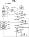
- a schematic configuration of an SLO apparatus 109 will be described in detail with reference to Fig. 1 .
- Light emitted from a light source 101 is split into a reference beam 105 and a measurement beam 106 by an optical coupler 131.
- the measurement beam 106 is guided to a subject's eye 107 which is an observation target after passing through a single-mode fiber 130-4, spatial light modulators 159-1 and 159-2, an XY scanner 119, spherical mirrors 160-1 to 160-9, and the like.
- the measurement beam 106 becomes a return beam 108 by being reflected or scattered by the subject's eye 107 and enters a detector 138.
- the detector 138 converts a light intensity of the return beam 108 into a voltage signal, and a planar image of the subject's eye 107 is formed using the voltage signal.
- the blood flow velocity is calculated using the acquired planar image.
- the overall optical system is configured using a reflection optical system which mainly uses spherical mirrors
- the overall optical system may be configured by a refractive optical system which uses lenses instead of spherical mirrors.
- a reflection type spatial light modulator is used, a transmission type spatial light modulator may be used.
- the light source 101 is a super luminescent diode (SLD) which is a typical low coherent light source.
- SLD super luminescent diode
- the light source 101 has a wavelength of 830 nm and a bandwidth of 50 nm.
- a low coherent light source is used to acquire a planar image with small speckle noise.
- an amplified spontaneous emission (ASE) or the like may be used as long as it can emit low coherent light.
- near-infrared light is suitable for the wavelength of the light source.
- the wavelength which is as short as possible can be adopted, and in the present exemplary embodiment, is 830 nm. Other wavelengths may be adopted according to a measurement region of an observation target.
- the beam emitted from the light source 101 is split into the reference beam 105 and the measurement beam 106 in the proportion of 96:4 after passing through the single-mode fiber 130-1 and the optical coupler 131.
- a polarization controller 153 is disposed between the light source 101 and the optical coupler 131.
- the reference beam 105 split by the optical coupler 131 enters a light amount measurement device 164 through an optical fiber 130-2.
- the light amount measurement device 164 is used for the purpose of measuring the light amount of the reference beam 105 and monitoring the light amount of the measurement beam 106.
- the measurement beam 106 split by the optical coupler 131 is guided to a lens 135-4 via the single-mode fiber 130-4 and is adjusted to be a parallel light having a beam diameter of 4 mm.
- the measurement beam 106 passes through a beam splitter 158 and enters a first spatial light modulator 159-1 after being reflected by the spherical mirrors 160-1 and 160-2.
- the first spatial light modulator 159-1 is disposed in a direction of modulating the phase of a P-polarized light (parallel to the sheet surface).
- the measurement beam 106 enters a second spatial light modulator 159-2 after being modulated by the first spatial light modulator 159-1 and reflected by spherical mirrors 160-3 and 160-4.
- the second spatial light modulator 159-2 is disposed in a direction of modulating the phase of an S-polarized light (perpendicular to the sheet surface). Since the spatial light modulators 159-1 and 159-2 generally perform modulation using the orientation of liquid crystals, the spatial light modulators 159-1 and 159-2 modulate only the polarization component of a specific direction.
- the orientation directions are not limited to being perpendicular but may be different from each other.
- the spatial light modulators 159-1 and 159-2 are controlled by the spatial light modulator driver 184 in a driver unit 181 from the PC 125.
- the measurement beam 106 enters a mirror of the XY scanner 119 after being modulated by the second spatial light modulator 159-2 and reflected by the spherical mirrors 160-5 and 160-6.
- the XY scanner 119 is described as including one mirror for the sake of simplicity, actually, the XY scanner 119 is one in which two mirrors of the X scanner and the Y scanner are disposed next to each other, and which performs raster scan over the retina 127 in a direction perpendicular to an optical axis.
- the center of the measurement beam 106 is adjusted to be identical to the rotation center of the mirror of the XY scanner 119.
- the X scanner is a scanner that scans the measurement beam 106 in a direction parallel to the sheet surface, and in the present exemplary embodiment, a resonance scanner is used.
- a driving frequency of the X scanner is about 7.9 kHz.
- the Y scanner is a scanner that scans the measurement beam 106 in a direction perpendicular to the sheet surface, and in the present exemplary embodiment, a galvano scanner is used.
- the Y scanner uses signal having a driving waveform of sawtooth wave, a driving frequency of 64 Hz, and a duty ratio of 16%.
- the driving frequency of the Y scanner is an important parameter in calculating the blood flow velocity since it determines an image capturing frame rate of the SLO apparatus 109. A different driving frequency may be used according to the blood flow velocity to be measured.
- the XY scanner 119 is controlled by an optical scanner driver 182 in the driver unit 181 from the PC 125.
- the spherical mirrors 160-7 to 160-9 are optical systems for scanning the retina 127 and perform the role of scanning the retina 127 about the vicinity of the cornea 126 with the measurement beam 106.
- the measurement beam 106 has a beam diameter of 4 mm, the beam diameter may be increased to acquire a high resolution tomographic image.
- a motor-driven stage 117 is configured to move in a direction indicated by an arrow in the drawing and to adjust the position of a spherical mirror 160-8 attached thereto.
- the motor-driven stage 117 is controlled by a motor-driven stage driver 183 in the driver unit 181 from the PC 125.
- the SLO apparatus 109 can cope with the subject's eye 107 having refractive error.
- the measurement beam 106 enters the subject's eye 107, the measurement beam 106 becomes the return beam 108 due to reflection or scattering from the retina 127, and the return beam 108 reaches the detector 138 through the single-mode fiber 130-3 by being guided again by the optical coupler 131.
- the detector 138 an avalanche photo diode (APD) or a photomultiplier tube (PMT) which is a high-speed, high-sensitive optical sensor can be used, for example.
- APD avalanche photo diode
- PMT photomultiplier tube
- the S-polarized light and the P-polarized light of the return beam 108 are modulated again by the second spatial light modulator 159-2 and the first spatial light modulator 159-1, respectively.
- the beam splitter 158 Apart of the return beam 108 split by the beam splitter 158 enters the wavefront sensor 155, and the aberration of the return beam 108 occurring in the subject's eye 107 is measured.
- the SLO apparatus 109 uses one wavefront sensor 155, the aberration may be measured for each polarization using two wavefront sensors.
- the wavefront sensor 155 is electrically connected to the PC 125.
- the spherical mirrors 160-1 to 160-9 are disposed so that they are optically conjugate to the cornea 126, the XY scanner 119, the wavefront sensor 155, and the spatial light modulators 159-1 and 159-2.
- the wavefront sensor 155 can measure the aberration of the subject's eye 107.
- the spatial light modulators 159-1 and 159-2 can correct the aberration of the subject's eye 107.
- the spatial light modulators 159-1 and 159-2 By controlling the spatial light modulators 159-1 and 159-2 in real time based on the aberration obtained from the measurement result by the wavefront sensor 155, the aberration occurring in the subject's eye 107 can be corrected. In this way, the planar image having a higher horizontal resolution can be acquired.
- a cylindrical mirror may be used instead of the spherical mirror 160-8 according to the aberration (refractive error) of the subject's eye 107.
- a new lens may be added to the optical path of the measurement beam 106.
- another light source may be used for measurement of the aberration.
- another optical path may be formed for measurement of the aberration.
- an aberration measurement beam may be incident using a beam splitter from a space between the spherical mirror 160-9 and the cornea 126.
- the SLO apparatus 109 can acquire the planar image (SLO image) which is formed based on the intensity of the return beam 108 from the retina 127.
- the return beam 108 which is the beam reflected or scattered by the retina 127 enters the detector 138 after passing the spherical mirrors 160-1 to 160-9, the spatial light modulators 159-1 and 159-2, and the optical coupler 131, and the intensity of the beam is converted into a voltage signal by the detector 138.
- the voltage signal obtained by the detector 138 is converted into a digital value by an analog-to-digital (AD) board 176 in the PC 125, and the digital data is processed by the PC 125 in synchronization with the operation and the driving frequency of the XY scanner 119, so that the planar image is formed.
- An acquisition speed of the AD board 176 is 15 MHz.
- a part of the return beam 108 split by the beam splitter 158 enters the wavefront sensor 155, and the aberration of the return beam 108 is measured.
- the wavefront sensor 155 is a Shack-Hartmann wavefront sensor.
- the obtained aberration is expressed by Zernike polynomial, which represents the aberration of the subject's eye 107.
- the Zernike polynomial includes a tilt (inclination) term, a defocus term, an astigmatism term, a coma term, and a trefoil term.
- the SLO apparatus 109 can acquire the planar image of the retina 127 by controlling the XY scanner 119 and acquiring the intensity of the return beam 108 using the detector 138.
- a method for acquiring the planar image (a plane perpendicular to the optical axis) of the retina 127 will be described.
- Fig. 2A is a schematic view of the subject's eye 107 and illustrates a state where the subject's eye 107 is observed by the SLO apparatus 109. As illustrated in Fig. 2A , when the measurement beam 106 enters the retina 127 through the cornea 126, the measurement beam 106 becomes the return beam 108 due to reflection or scattering at various positions, and the return beam 108 reaches the detector 138.
- the XY scanner 109 is moved in the X direction, and the intensity of the return beam 108 is detected, so that information at each position on the X axis can be obtained.
- the XY scanner 109 is moved in both the X and Y axes, and the measurement beam 106 is raster-scanned along a trajectory 193 on an image capturing range 192 where the retina 127 is present.
- the intensity of the return beam 108 is detected, so that a two-dimensional distribution of the intensity of the return beam 108 can be obtained, which is the planar image 177 (see Fig. 2D ).
- the measurement beam 106 is scanned from a right point S to a bottom left point E, and during the scanning, the intensity of the return beam 108 is used for forming the planar image 177.
- the trajectory 193 from the point E to the point S is the movement of the measurement beam 106 for preparation of the image capturing of the planar image 177.
- the period required for the scanning takes 84% for the point S to the point E and 16% for the point E to the point S for the trajectory 193 illustrated in the drawing, and this ratio is based on the duty ratio of the driving waveform of the Y scanner described above.
- the number of times of the scanning in the X direction of the trajectory 193 is smaller than the actual number of times.
- the planar image 177 has a size of 700 ⁇ 350 ⁇ m, and the time required for acquisition is about 15.6 millisecond. This time is based on the driving frequency of the Y scanner.
- a visual cell group 179 where the intensity of the return beam 108 is relatively high is visualized brightly, whereas a blood vessel 178 where the intensity is relatively low is visualized darkly. Further, blood cells (not illustrated) are visualized brightly in the blood vessel 178.
- Spatiotemporal images may be created by extracting the blood vessel 178 where blood cells are visualized from the planar images 177 continuously acquired and superimposing the extracted planar images 177 in the order of capturing. In this way, the movement of the blood cells and the blood flow velocity can be understood easily.
- the SLO apparatus 109 can successively acquire the planar images by successively raster-scanning the image capturing range where the retina 127 is present using the XY scanner 119.
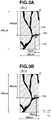
- Figs. 3A and 3B illustrate planar images 191-1 and 191-2 acquired continuously over time by the above-described method.
- the planar images 191-1 and 191-2 are displayed in parallel on the display of the PC 125.
- the planar images 191-1 and 191-2 include the blood vessel 178, the visual cell group 179, and the blood cell 194.
- a method for calculating the moving velocity of the blood cell 194, namely the blood flow velocity will be described with reference to the planar images 191-1 and 191-2.
- the blood flow velocity calculation method involves the following operations (1) to (5).
- the following operations may be automatically performed using a computer such as the PC 125.
- the blood flow velocity calculation apparatus includes the spatial light modulation unit capable of modulating at least one of the measurement beam and the return beam, the aberration measurement unit that measures the aberration occurring in the subject's eye, and the control unit that controls the amount of modulation in the spatial light modulation unit based on the measurement result by the aberration measurement unit to correct the aberration. Further, the spatial light modulation unit is configured to perform modulation at a position that is optically conjugate to the aberration measurement unit. With this configuration, the blood flow velocity calculation apparatus can acquire a planar image with a high horizontal resolution and calculate a blood flow velocity of a finer blood vessel.
- the blood flow velocity calculation apparatus calculates the moving velocity of the blood cell based on the difference in time when the blood cell is captured.
- the difference between the blood flow velocity obtained with the present invention and the blood flow velocity obtained with the conventional technique is noticeable when the blood cell rarely moves in the Y direction of the planar image, for example.
- the present invention provides a noticeable effect over the conventional technique when the blood cell rarely moves in the Y direction of the planar image, for example .
- a composite apparatus of an SLO apparatus and an optical coherence tomography (OCT) apparatus will be described as an example of an optical image capturing apparatus.
- OCT optical coherence tomography
- a composite apparatus which includes an adaptive optics system and which captures both a high horizontal resolution planar image (SLO image) and a tomographic image (OCT image) of a retina and calculates a blood flow velocity using the acquired planar and tomographic images will be described.
- the SLO apparatus is configured to correct an optical aberration of a subject's eye using a spatial light modulator to acquire a planar image
- a Fourier domain OCT apparatus is configured to acquire a tomographic image, so that favorable planar image and tomographic image are obtained regardless of a diopter of the subject's eye and an optical aberration.
- a schematic configuration of a composite apparatus 100 according to the present exemplary embodiment will be described in detail with reference to Fig. 4 .
- Fig. 4 the same constituent elements as the first exemplary embodiment illustrated in Fig. 1 are denoted by the same reference numerals, and the description thereof will not be repeated.
- a beam emitted from a light source 101 is split into a reference beam 105 and a measurement beam 106 by an optical coupler 131.
- the measurement beam 106 is guided to a subject's eye 107 which is an observation target after passing through a single-mode fiber 130-4, a spatial light modulator 159, an XY scanner 119, an X scanner 121, spherical mirrors 160-1 to 160-9, and the like.
- the measurement beam 106 becomes a return beam 108 by being reflected or scattered by the subject's eye 107 and enters a detector 138 or a line sensor 139.
- the detector 138 converts light intensity of the return beam 108 into a voltage signal, and a planar image of the subject's eye 107 is formed using the voltage signal.
- the blood flow velocity is calculated using the acquired planar image.
- the line sensor 139 receives the reference beam 105 and the return beam 108, and tomographic images of the subject's eye 107 are formed. A three-dimensional movement of a blood vessel is visualized using a plurality of acquired tomographic images.
- the spatial light modulator is used as a device for correcting a wavefront aberration
- a variable shape mirror may be used as long as it can correct the wavefront aberration.
- the light source 101 is the same as the first exemplary embodiment, and the description thereof will not be repeated.
- An SLD which is a low coherent light source is also suitable for capturing tomographic images.
- the reference beam 105 split by the optical coupler 131 is guided to a lens 135-1 after passing through the single-mode fiber 130-2 and is adjusted to be a parallel light having a beam diameter of 4 mm.
- the reference beam 105 is guided to a mirror 114 which is a reference mirror by mirrors 157-1 to 157-4. Since an optical path length of the reference beam 105 is adjusted to be approximately the same as an optical path length of the measurement beam 106, it is possible to cause the reference beam 105 to interfere with the measurement beam 106.
- the reference beam 105 is reflected by the mirror 114 and is again guided to the optical coupler 131.
- the reference beam 105 passes through a dispersion compensation glass 115 which compensates the reference beam 105 for dispersion of when the measurement beam 106 makes a round trip to the subject's eye 107.
- a motor-driven stage 117-1 is configured to move in a direction indicated by an arrow in the drawing and to adjust and control the optical path length of the reference beam 105.
- the motor-driven stage 117-1 is controlled by a motor-driven stage driver 183 in a driver unit 181 from a PC 125.
- the measurement beam 106 split by the optical coupler 131 is guided to a lens 135-4 via the single-mode fiber 130-4 and is adjusted to be a parallel light having a beam diameter of 4 mm.
- a polarization controller 153-1 or 153-2 is configured to adjust the polarization state of the measurement beam 106.
- the polarization state of the measurement beam 106 is adjusted to be a linearly polarized light parallel to the sheet surface.
- the measurement beam 106 passes through a beam splitter 158 and a movable beam splitter 161 (also referred to as a branch unit) and enters a spatial light modulator 159 via spherical mirrors 160-1 and 160-2, and the measurement beam 106 is modulated by the spatial light modulator 159.
- the spatial light modulator 159 is a modulator that performs modulation utilizing the orientation of liquid crystal.
- the spatial light modulator 159 is disposed in a direction of modulating the phase of a linearly polarized light (P-polarized light) that is parallel to the sheet surface, and is identical to the direction of the polarization of the measurement beam 106.
- P-polarized light linearly polarized light
- the measurement beam 106 further passes through a polarizing plate 173 and enters a mirror of the X scanner 121 via spherical mirrors 160-3 and 160-4.
- the polarizing plate 173 has a function of guiding only the linearly polarized light parallel to the sheet surface among the return beam 108 to the spatial light modulator 159.
- the X scanner 121 is an X scanner that scans the measurement beam 106 in a direction parallel to the sheet surface, and in the present exemplary embodiment, a resonance scanner is used.
- a driving frequency of the X scanner 121 is about 7.9 kHz.
- the measurement beam 106 enters a mirror of the XY scanner 119 via spherical mirrors 160-5 and 160-6.
- the XY scanner 119 is described as including one mirror for the sake of simplicity, actually, the XY scanner 119 is one in which two mirrors of the X and Y scanners are disposed next to each other.
- the center of the measurement beam 106 is adjusted to be identical to the rotation center of the mirror of the XY scanner 119.
- a driving frequency of the XY scanner 119 is variable in the range of ⁇ 500 Hz.
- Spherical mirrors 160-7 to 160-9 are optical systems for scanning the retina 127 and perform the role of scanning the retina 127 about the vicinity of the cornea 126 with the measurement beam 106.
- a motor-driven stage 117-2 is configured to move in a direction indicated by an arrow in the drawing and to adjust and control the position of the spherical mirror 160-8 attached thereto. Similarly to the motor-driven stage 117-1, the motor-driven stage 117-2 is controlled by the motor-driven stage driver 183.
- the position of the spherical mirror 160-8 By adjusting the position of the spherical mirror 160-8, it is possible to focus the measurement beam 106 on a predetermined layer of the retina 127 of the subject's eye 107 and observe the subject's eye 107. In the initial state, the position of the spherical mirror 160-8 is adjusted so that the measurement beam 106 can enter the cornea 126 as a parallel light.
- the composite apparatus 100 can cope with the subject's eye 107 having refractive error.
- the measurement beam 106 enters the subject's eye 107, the measurement beam 106 becomes the return beam 108 due to reflection or scattering from the retina 127, and the return beam 108 reaches a line camera 139 by being guided again by the optical coupler 131.
- a part of the return beam 108 is reflected by the movable beam splitter 161 and guided to the detector 138 through the lens 135-5.
- a light blocking plate 172 having a pinhole has a function of blocking unnecessary beam that is not focused on the retina 127 among the return beam 108. Further, the light blocking plate 172 is disposed to be conjugate to the focusing position of the lens 135-5. The diameter of the pinhole of the light blocking plate 172 is 50 ⁇ m, for example.
- an avalanche photo diode (APD) which is a high-speed, high-sensitive optical sensor is used, for example.
- the wavefront sensor 155 is a Shack-Hartmann wavefront sensor.
- the spherical mirrors 160-1 to 160-9 are disposed so that they are optically conjugate to the XY scanner 119, the X scanner 121, the cornea 126, the wavefront sensor 155, and the spatial light modulator 159.
- the wavefront sensor 155 can measure the aberration of the subject's eye 107.
- the spatial light modulator 159 can correct the aberration of the subject's eye 107. Furthermore, by controlling the spatial light modulator 159 in real time based on the obtained aberration, it is possible to correct the aberration occurring in the subject's eye 107 and to acquire higher horizontal resolution tomographic images.
- the composite apparatus 100 can acquire tomographic images (OCT images) and planar images (SLO images) .
- the return beam 108 is multiplexed by the optical coupler 131.
- the multiplexed beam 142 is guided to a transmission type grating 141 through the single-mode fiber 130-3 and the lens 135-2 and is then dispersed for each wavelength, and enters the line camera 139 through the lens 135-3.
- the line camera 139 converts the light intensity for each position (wavelength) into a voltage signal.
- the voltage signal is converted into a digital value by a frame grabber 140, so that tomographic images of the subject's eye 107 are formed in the PC 125.
- the line camera 139 includes 1024 pixels, and can obtain the intensity of the multiplexed beam 142 for each wavelength (with a division of 1024).
- a part of the return beam 108 is reflected by the movable beam splitter 161.
- the reflected beam reaches the detector 138 after the unnecessary beam is blocked by the light blocking plate 172, and the light intensity is converted into an electrical signal.
- Data of the obtained electrical signal is processed by the PC 125 in synchronization with the scanning signal of the X scanner 121 and the XY scanner 119, so that planar images are formed.
- the wavefront sensor 155 Apart of the return beam 108 split by the beam splitter 158 enters the wavefront sensor 155, and the aberration of the return beam 108 is measured. An image signal obtained by the wavefront sensor 155 is supplied to the PC 125, and an aberration is calculated. The obtained aberration is expressed by Zernike polynomial, which represents the aberration of the subject's eye 107.
- the Zernike polynomial includes a tilt (inclination) term, a defocus term, an astigmatism term, a coma term, and a trefoil term.
- the composite apparatus 100 can acquire a tomographic image of the retina 127 by controlling the XY scanner 119 and acquiring an interference pattern with the line camera 139 using the X scanner 121 as a fixed mirror.
- the movable beam splitter 161 is controlled so that the return beam 108 is not guided to the detector 138.
- the X scanner 121 and the XY scanner 119 are controlled by the optical scanner driver 182 in the driver unit 181 from the PC 125 (see Fig. 4 ) .
- a method for acquiring a tomographic image (a plane parallel to the optical axis) of the retina 127 will be described.
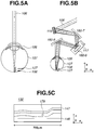
- Fig. 5A is a schematic view of the subject's eye 107 and illustrates a state where the subject's eye 107 is observed by the composite apparatus 100.
- the measurement beam 106 enters the retina 127 through the cornea 126
- the measurement beam 106 becomes the return beams 108 due to reflection or scattering at various positions, and the return beams 108 reach the line camera 139 with delays at the respective positions.
- the line camera 139 can detect an interference pattern when the optical path length of the reference optical path is approximately the same as the optical path length of the measurement optical path.
- the interference pattern acquired by the line camera 139 is an interference pattern in a spectrum region on the wavelength axis.
- the interference pattern which is information on the wavelength axis is converted into an interference pattern on an optical frequency axis by taking the characteristics of the line camera 139 and the transmission type grating 141 into consideration. Further, by performing inverse Fourier transform on the obtained interference pattern on the optical frequency axis, it is possible to obtain information in a depth direction.
- the interference pattern when the interference pattern is detected while moving the XY scanner 119, the interference pattern can be obtained at each position on the X axis. More specifically, the information in the depth direction can be obtained at each position on the X axis. As a result, a two-dimensional distribution of the intensity of the return beam 108 on the XZ plane can be obtained, which is a tomographic image 132 (see Fig. 5C ).
- the tomographic image 132 is one in which the intensity of the return beam 108 is arranged in an array, and the intensity is displayed by applying a gray scale.
- a length of the tomographic image 132 in the X direction is 700 ⁇ m, which is the same as a SLO image described below.
- the tomographic image includes a retinal pigment epithelial layer 146, a stratum opticum 147, and a blood vessel 178.
- the tomographic image includes a retinal pigment epithelial layer 146, a stratum opticum 147, and a blood vessel 178.
- the composite apparatus 100 can acquire a planar image of the retina 127 by controlling and operating the XY scanner 119 in only the Y-axis direction and the X scanner 121 while fixing the X-axis direction of the XY scanner 119 and acquiring the intensity of the return beam 108 with the detector 138.
- the X scanner 121 and the XY scanner 119 are controlled by the optical scanner driver 182 in the driver unit 181 from the PC 125 (see Fig. 4 ).
- the composite apparatus 100 can acquire a planar image while correcting the aberration occurring in the subject's eye 107 by controlling the spatial light modulator 159 using the aberration of the subject's eye 107 measured by the wavefront sensor 155. Moreover, the composite apparatus 100 can acquire a planar image while controlling the spatial light modulator 159 in real time.
- the specific planar image acquisition method is the same as the first exemplary embodiment, and thus the description thereof will not be repeated.
- a method for calculating a blood flow velocity from an acquired planar image is the same as the first exemplary embodiment, and thus the description thereof will not be repeated.
- the blood vessel visualized in the acquired planar image is considered to be a blood vessel which moves three-dimensionally and which is projected on the XY plane.
- the measured blood flow velocity is the velocity on the XY plane.
- the composite apparatus according to the present exemplary embodiment can grasp the three-dimensional movement of the blood vessel using a plurality of tomographic images and calculate the velocity in the XYZ space using the measured blood flow velocity on the XY plane.
- the optical image capturing apparatus includes the splitting unit that splits a beam from the light source into a measurement beam and a reference beam, the interference unit that causes a return beam of the measurement beam irradiated on a subject's eye to interfere with the reference beam having passed through the reference optical path, and the detection unit that detects an intensity of an interference signal resulting from the interference.
- the optical image capturing apparatus has the function of capturing a tomographic image of the subject's eye, and most of the optical systems share the purpose of capturing tomographic images and the purpose of capturing planar images.
- the optical image capturing apparatus can capture planar images and tomographic images with a simple configuration and grasp a three-dimensional movement of a blood vessel.
- the optical image capturing apparatus can calculate a blood flow velocity in an XYZ space.
Landscapes
- Health & Medical Sciences (AREA)
- Life Sciences & Earth Sciences (AREA)
- Physics & Mathematics (AREA)
- Animal Behavior & Ethology (AREA)
- Public Health (AREA)
- Veterinary Medicine (AREA)
- Engineering & Computer Science (AREA)
- Biomedical Technology (AREA)
- Heart & Thoracic Surgery (AREA)
- Medical Informatics (AREA)
- Molecular Biology (AREA)
- Surgery (AREA)
- Biophysics (AREA)
- General Health & Medical Sciences (AREA)
- Ophthalmology & Optometry (AREA)
- Hematology (AREA)
- Nuclear Medicine, Radiotherapy & Molecular Imaging (AREA)
- Radiology & Medical Imaging (AREA)
- Vascular Medicine (AREA)
- General Physics & Mathematics (AREA)
- Cardiology (AREA)
- Physiology (AREA)
- Pathology (AREA)
- Eye Examination Apparatus (AREA)
- Measuring Pulse, Heart Rate, Blood Pressure Or Blood Flow (AREA)
Claims (9)
- Appareil ophtalmique, comprenant :un moyen d'exposition à un rayonnement configuré pour exposer un œil d'un sujet à un rayonnement d'un faisceau de mesure balayé par un moyen de balayage (119) ;un moyen d'acquisition (125) configuré pour acquérir une image de l'œil du sujet sur la base d'un faisceau de retour, renvoyé de l'œil du sujet, du faisceau de mesure projeté par le moyen d'exposition à un rayonnement ; etun moyen de calcul (125) configuré pour calculer une vitesse de circulation sanguine de l'œil du sujet sur la base d'un décalage entre une position d'une cellule sanguine dans une première image obtenue par le moyen d'acquisition (125) et une position de la cellule sanguine dans une seconde image obtenue par le moyen d'acquisition (125) à un instant différent de celui de la première image, et d'une différence entre un instant auquel a été obtenue une image de la cellule sanguine dans la première image et un instant auquel a été obtenue une image de la cellule sanguine dans la seconde image,dans lequel le moyen de calcul calcule la vitesse de circulation sanguine de l'œil du sujet sur la base du décalage et d'une période qu'il faut au moyen de balayage pour balayer le faisceau de mesure de la position de la cellule sanguine dans la première image à la position de la cellule sanguine dans la seconde image.
- Appareil ophtalmique selon la revendication 1, comprenant en outre un moyen d'affichage configuré pour afficher l'image de l'œil du sujet acquise par le moyen d'acquisition (125).
- Appareil ophtalmique selon la revendication 2, comprenant en outre un moyen de traitement d'image (125) configuré pour appliquer un traitement d'image à la première image et à la seconde image de façon à mettre en évidence et à afficher la cellule sanguine comprise dans les première et seconde images sur le moyen d'affichage.
- Appareil ophtalmique selon la revendication 2 ou la revendication 3, comprenant en outre un moyen de sélection configuré pour sélectionner la cellule sanguine comprise dans la première image et dans la seconde image affichées sur le moyen d'affichage,
dans lequel le moyen de calcul (125) calcule la vitesse de circulation sanguine de l'œil du sujet sur la base du décalage et de la différence entre la cellule sanguine comprise dans la première image et de la même cellule sanguine dans la seconde image, sélectionnée par le moyen de sélection. - Appareil ophtalmique selon l'une quelconque des revendications 1 à 4, comprenant en outre un moyen de création d'image (125) configuré pour créer une image spatio-temporelle au moyen de la première image et de la seconde image.
- Appareil ophtalmique selon l'une quelconque des revendications 1 à 5, comprenant en outre :un moyen de mesure d'aberration (155) configuré pour mesurer une aberration apparaissant dans l'œil du sujet ;un moyen de modulation spatiale de lumière (159-1 et 159-2) qui est disposé à une position conjuguée au moyen de mesure d'aberration (155) et configuré pour moduler au moins l'un du faisceau de mesure et du faisceau de retour ; etun moyen de commande (184) configuré pour commander une quantité de modulation du moyen de modulation spatiale de lumière (159-1 et 159-2) sur la base d'un résultat de mesure obtenu par le moyen de mesure d'aberration (155) pour corriger l'aberration.
- Appareil ophtalmique selon l'une quelconque des revendications 1 à 6, comprenant en outre :un moyen de division (131) configuré pour diviser un faisceau provenant d'une source de lumière en le faisceau de mesure et un faisceau de référence ;un moyen d'interférence (131) configuré pour amener le faisceau de retour du faisceau de mesure projeté vers l'œil du sujet à interférer avec le faisceau de référence qui est passé par un trajet optique de référence ;un moyen de détection (139) configuré pour détecter une intensité d'un signal d'interférence obtenu à partir de l'interférence ; etun moyen d'acquisition d'image tomographique (125) configuré pour acquérir une image tomographique de l'œil du sujet sur la base de l'intensité détectée par le moyen de détection (139).
- Appareil ophtalmique selon la revendication 7, comprenant en outre :un moyen de conversion (138) configuré pour détecter le faisceau de retour, provenant de l'œil du sujet, du faisceau de mesure et pour convertir le faisceau détecté en un signal électrique ; etun moyen de guidage de lumière (161) configuré pour guider le faisceau de retour vers le moyen de conversion sur un trajet optique qui relie la source de lumière et l'œil du sujet,dans lequel le moyen d'acquisition (125) acquiert l'image de l'œil du sujet sur la base d'une intensité du signal électrique obtenue par le moyen de conversion.
- Procédé de calcul d'une vitesse de circulation sanguine, le procédé comprenant les étapes consistant à :exposer un œil d'un sujet à un rayonnement d'un faisceau de mesure balayé par un moyen de balayage (119) ;acquérir une image de l'œil du sujet sur la base d'un faisceau de retour, provenant de l'œil du sujet, du faisceau de mesure projeté ; etcalculer une vitesse de circulation sanguine de l'œil du sujet sur la base d'un décalage entre une position d'une cellule sanguine dans une première image acquise et une position de la cellule sanguine dans une seconde image acquise à un instant différent de celui de la première image, et d'une différence entre un instant auquel a été obtenue une image de la cellule sanguine dans la première image et un instant auquel a été obtenue une image de la cellule sanguine dans la seconde image,dans lequel la vitesse de circulation sanguine de l'œil du sujet est calculée sur la base du décalage et d'une période qu'il faut au moyen de balayage pour balayer le faisceau de mesure de la position de la cellule sanguine dans la première image à la position de la cellule sanguine dans la seconde image.
Applications Claiming Priority (1)
| Application Number | Priority Date | Filing Date | Title |
|---|---|---|---|
| JP2010269741A JP5721412B2 (ja) | 2010-12-02 | 2010-12-02 | 眼科装置、血流速算出方法およびプログラム |
Publications (2)
| Publication Number | Publication Date |
|---|---|
| EP2460461A1 EP2460461A1 (fr) | 2012-06-06 |
| EP2460461B1 true EP2460461B1 (fr) | 2021-03-31 |
Family
ID=45217271
Family Applications (1)
| Application Number | Title | Priority Date | Filing Date |
|---|---|---|---|
| EP11190584.0A Active EP2460461B1 (fr) | 2010-12-02 | 2011-11-24 | Détermination de la vitesse du flux sanguin rétinien |
Country Status (5)
| Country | Link |
|---|---|
| US (1) | US8770752B2 (fr) |
| EP (1) | EP2460461B1 (fr) |
| JP (1) | JP5721412B2 (fr) |
| KR (1) | KR101477084B1 (fr) |
| CN (1) | CN102525409B (fr) |
Families Citing this family (29)
| Publication number | Priority date | Publication date | Assignee | Title |
|---|---|---|---|---|
| JP5610884B2 (ja) | 2010-07-09 | 2014-10-22 | キヤノン株式会社 | 光断層撮像装置及び光断層撮像方法 |
| JP5936368B2 (ja) * | 2012-01-20 | 2016-06-22 | キヤノン株式会社 | 光干渉断層撮影装置及びその作動方法 |
| JP2013148509A (ja) | 2012-01-20 | 2013-08-01 | Canon Inc | 画像処理装置及び画像処理方法 |
| JP6039185B2 (ja) | 2012-01-20 | 2016-12-07 | キヤノン株式会社 | 撮影装置 |
| JP5988772B2 (ja) | 2012-01-20 | 2016-09-07 | キヤノン株式会社 | 画像処理装置及び画像処理方法 |
| JP6061554B2 (ja) | 2012-01-20 | 2017-01-18 | キヤノン株式会社 | 画像処理装置及び画像処理方法 |
| JP6146951B2 (ja) | 2012-01-20 | 2017-06-14 | キヤノン株式会社 | 画像処理装置、画像処理方法、撮影装置及び撮影方法 |
| JP5979904B2 (ja) | 2012-02-20 | 2016-08-31 | キヤノン株式会社 | 画像処理装置、眼科撮影システム、及び画像処理方法 |
| JP6101048B2 (ja) * | 2012-02-20 | 2017-03-22 | キヤノン株式会社 | 画像処理装置及び画像処理方法 |
| JP5867720B2 (ja) * | 2012-03-29 | 2016-02-24 | 株式会社トプコン | 画像表示装置、画像表示方法、及びプログラム |
| EP2829219B1 (fr) | 2012-03-12 | 2020-09-09 | Kabushiki Kaisha Topcon | Dispositif optique de mesure d'image |
| JP5867719B2 (ja) * | 2012-03-12 | 2016-02-24 | 株式会社トプコン | 光画像計測装置 |
| US9541375B2 (en) | 2012-07-20 | 2017-01-10 | Samsung Electronics Co., Ltd. | Method and apparatus for generating tomography images |
| WO2014031961A1 (fr) * | 2012-08-23 | 2014-02-27 | University Of Washington Through Its Center For Commercialization | Procédés et systèmes de détermination de propriétés volumétriques d'un tissu |
| JP6092659B2 (ja) * | 2013-02-28 | 2017-03-08 | キヤノン株式会社 | 画像処理装置及び画像処理方法 |
| WO2014163897A1 (fr) | 2013-03-13 | 2014-10-09 | Optimedica Corporation | Interface patient à flottement libre pour système de chirurgie laser |
| EP3434235B1 (fr) | 2013-03-13 | 2023-04-26 | AMO Development, LLC | Système de chirurgie oculaire au laser |
| US9844320B2 (en) * | 2014-01-29 | 2017-12-19 | University Of Rochester | System and method for observing an object in a blood vessel |
| CN104825148B (zh) | 2015-05-27 | 2017-11-14 | 深圳市斯尔顿科技有限公司 | 一种测量血管血液流量的设备及方法 |
| JP6633468B2 (ja) * | 2015-08-26 | 2020-01-22 | 株式会社トプコン | 血流計測装置 |
| CN105748041B (zh) * | 2016-02-15 | 2018-07-03 | 苏州大学 | 光学相干断层扫描成像中散斑噪声的抑制系统和方法 |
| GB2543592B (en) | 2016-03-30 | 2018-08-01 | The Science And Tech Facilities Council | Imaging a retina of an eye |
| CN110141188B (zh) * | 2019-05-15 | 2023-08-08 | 佛山科学技术学院 | 一种大视场眼底相机均匀照明方法及系统 |
| USD1064287S1 (en) | 2022-03-14 | 2025-02-25 | O/D Vision Inc. | Consumer electronics device |
| US12380735B2 (en) | 2022-03-14 | 2025-08-05 | O/D Vision Inc. | Systems and methods for biometric identification using patterns and blood flow characteristics of the outer eye |
| US12381009B2 (en) | 2022-03-14 | 2025-08-05 | O/D Vision Inc. | Systems and methods for artificial intelligence based standard of care support |
| US12285243B2 (en) | 2022-03-14 | 2025-04-29 | O/D Vision Inc. | Multi sensor handheld medical diagnostic device |
| US12257025B2 (en) | 2022-03-14 | 2025-03-25 | O/D Vision Inc. | AI enabled multisensor connected telehealth system |
| US12293837B2 (en) | 2022-03-14 | 2025-05-06 | O/D Vision Inc. | Systems and methods for artificial intelligence based warning of potential health concerns |
Family Cites Families (10)
| Publication number | Priority date | Publication date | Assignee | Title |
|---|---|---|---|---|
| US5501226A (en) * | 1994-10-19 | 1996-03-26 | Carl Zeiss, Inc. | Short coherence length, doppler velocimetry system |
| US5976502A (en) * | 1997-10-21 | 1999-11-02 | Gholam A. Peyman | Method of visualizing particles and blood cells containing a fluorescent lipophilic dye in the retina and choroid of the eye |
| EP1427328B1 (fr) * | 2001-08-30 | 2014-07-02 | University Of Rochester | Optique adaptative dans un ophtalmoscope laser a balayage |
| JP3855024B2 (ja) | 2001-12-13 | 2006-12-06 | 国立大学法人九州工業大学 | 血流速度測定装置 |
| AU2003227315A1 (en) * | 2002-04-02 | 2003-10-13 | Yeda Research And Development Co. Ltd. | Characterization of moving objects in a stationary background |
| FR2868279B1 (fr) * | 2004-04-02 | 2006-06-09 | Mauna Kea Technologies Soc Par | Procede et systeme de mesure de vitesse du flux sanguin |
| JP4783219B2 (ja) * | 2006-06-16 | 2011-09-28 | 株式会社トプコン | 眼科撮影装置 |
| JP4822969B2 (ja) * | 2006-07-27 | 2011-11-24 | 株式会社ニデック | 眼科撮影装置 |
| JP2010017396A (ja) * | 2008-07-11 | 2010-01-28 | Olympus Corp | 生体観察方法および装置 |
| WO2011066546A1 (fr) * | 2009-11-30 | 2011-06-03 | The Board Of Trustees Of The University Of Illinois | Evaluation de la circulation microvasculaire |
-
2010
- 2010-12-02 JP JP2010269741A patent/JP5721412B2/ja not_active Expired - Fee Related
-
2011
- 2011-11-24 EP EP11190584.0A patent/EP2460461B1/fr active Active
- 2011-11-28 US US13/305,629 patent/US8770752B2/en not_active Expired - Fee Related
- 2011-11-29 KR KR1020110125550A patent/KR101477084B1/ko not_active Expired - Fee Related
- 2011-12-02 CN CN201110400327.4A patent/CN102525409B/zh not_active Expired - Fee Related
Non-Patent Citations (1)
| Title |
|---|
| None * |
Also Published As
| Publication number | Publication date |
|---|---|
| CN102525409A (zh) | 2012-07-04 |
| JP5721412B2 (ja) | 2015-05-20 |
| CN102525409B (zh) | 2015-12-16 |
| US8770752B2 (en) | 2014-07-08 |
| JP2012115573A (ja) | 2012-06-21 |
| EP2460461A1 (fr) | 2012-06-06 |
| KR101477084B1 (ko) | 2014-12-29 |
| US20120140170A1 (en) | 2012-06-07 |
| KR20120060746A (ko) | 2012-06-12 |
Similar Documents
| Publication | Publication Date | Title |
|---|---|---|
| EP2460461B1 (fr) | Détermination de la vitesse du flux sanguin rétinien | |
| JP5721411B2 (ja) | 眼科装置、血流速算出方法およびプログラム | |
| US11058293B2 (en) | Image processing apparatus, ophthalmologic imaging apparatus, image processing method, and storage medium | |
| KR101477591B1 (ko) | 광학 단층촬영 화상 촬상장치 및 그 제어 방법 | |
| KR101321779B1 (ko) | 광화상 촬상장치 및 광화상의 촬상방법 | |
| US9875541B2 (en) | Enhanced algorithm for the detection of eye motion from fundus images | |
| JP6039908B2 (ja) | 撮像装置及び撮像装置の制御方法 | |
| US10849499B2 (en) | Ophthalmologic apparatus and method of controlling the same | |
| JP5847510B2 (ja) | 画像処理装置及び画像処理方法 | |
| WO2010113476A1 (fr) | Appareil de mesure d'image optique | |
| US20160106312A1 (en) | Data processing method and oct apparatus | |
| KR20130085978A (ko) | 화상처리장치 및 화상처리방법 | |
| GB2516146A (en) | Fundus imaging apparatus and imaging method | |
| JP6108811B2 (ja) | 撮像装置 | |
| US10433721B2 (en) | Ophthalmic apparatus and control method for the same | |
| JP5587014B2 (ja) | 眼科装置 | |
| US10130249B2 (en) | Inspection apparatus, image processing apparatus, method of operating inspection apparatus, image processing method, and recording medium | |
| JP2012225826A (ja) | 干渉光計測装置 |
Legal Events
| Date | Code | Title | Description |
|---|---|---|---|
| PUAI | Public reference made under article 153(3) epc to a published international application that has entered the european phase |
Free format text: ORIGINAL CODE: 0009012 |
|
| AK | Designated contracting states |
Kind code of ref document: A1 Designated state(s): AL AT BE BG CH CY CZ DE DK EE ES FI FR GB GR HR HU IE IS IT LI LT LU LV MC MK MT NL NO PL PT RO RS SE SI SK SM TR |
|
| AX | Request for extension of the european patent |
Extension state: BA ME |
|
| 17P | Request for examination filed |
Effective date: 20121206 |
|
| STAA | Information on the status of an ep patent application or granted ep patent |
Free format text: STATUS: EXAMINATION IS IN PROGRESS |
|
| 17Q | First examination report despatched |
Effective date: 20180717 |
|
| GRAP | Despatch of communication of intention to grant a patent |
Free format text: ORIGINAL CODE: EPIDOSNIGR1 |
|
| STAA | Information on the status of an ep patent application or granted ep patent |
Free format text: STATUS: GRANT OF PATENT IS INTENDED |
|
| INTG | Intention to grant announced |
Effective date: 20200312 |
|
| GRAJ | Information related to disapproval of communication of intention to grant by the applicant or resumption of examination proceedings by the epo deleted |
Free format text: ORIGINAL CODE: EPIDOSDIGR1 |
|
| STAA | Information on the status of an ep patent application or granted ep patent |
Free format text: STATUS: EXAMINATION IS IN PROGRESS |
|
| INTC | Intention to grant announced (deleted) | ||
| GRAP | Despatch of communication of intention to grant a patent |
Free format text: ORIGINAL CODE: EPIDOSNIGR1 |
|
| STAA | Information on the status of an ep patent application or granted ep patent |
Free format text: STATUS: GRANT OF PATENT IS INTENDED |
|
| INTG | Intention to grant announced |
Effective date: 20201116 |
|
| GRAS | Grant fee paid |
Free format text: ORIGINAL CODE: EPIDOSNIGR3 |
|
| GRAA | (expected) grant |
Free format text: ORIGINAL CODE: 0009210 |
|
| STAA | Information on the status of an ep patent application or granted ep patent |
Free format text: STATUS: THE PATENT HAS BEEN GRANTED |
|
| AK | Designated contracting states |
Kind code of ref document: B1 Designated state(s): AL AT BE BG CH CY CZ DE DK EE ES FI FR GB GR HR HU IE IS IT LI LT LU LV MC MK MT NL NO PL PT RO RS SE SI SK SM TR |
|
| REG | Reference to a national code |
Ref country code: GB Ref legal event code: FG4D Ref country code: CH Ref legal event code: EP |
|
| REG | Reference to a national code |
Ref country code: DE Ref legal event code: R096 Ref document number: 602011070534 Country of ref document: DE Ref country code: AT Ref legal event code: REF Ref document number: 1375995 Country of ref document: AT Kind code of ref document: T Effective date: 20210415 |
|
| REG | Reference to a national code |
Ref country code: IE Ref legal event code: FG4D |
|
| REG | Reference to a national code |
Ref country code: LT Ref legal event code: MG9D |
|
| PG25 | Lapsed in a contracting state [announced via postgrant information from national office to epo] |
Ref country code: NO Free format text: LAPSE BECAUSE OF FAILURE TO SUBMIT A TRANSLATION OF THE DESCRIPTION OR TO PAY THE FEE WITHIN THE PRESCRIBED TIME-LIMIT Effective date: 20210630 Ref country code: BG Free format text: LAPSE BECAUSE OF FAILURE TO SUBMIT A TRANSLATION OF THE DESCRIPTION OR TO PAY THE FEE WITHIN THE PRESCRIBED TIME-LIMIT Effective date: 20210630 Ref country code: HR Free format text: LAPSE BECAUSE OF FAILURE TO SUBMIT A TRANSLATION OF THE DESCRIPTION OR TO PAY THE FEE WITHIN THE PRESCRIBED TIME-LIMIT Effective date: 20210331 Ref country code: FI Free format text: LAPSE BECAUSE OF FAILURE TO SUBMIT A TRANSLATION OF THE DESCRIPTION OR TO PAY THE FEE WITHIN THE PRESCRIBED TIME-LIMIT Effective date: 20210331 |
|
| PG25 | Lapsed in a contracting state [announced via postgrant information from national office to epo] |
Ref country code: SE Free format text: LAPSE BECAUSE OF FAILURE TO SUBMIT A TRANSLATION OF THE DESCRIPTION OR TO PAY THE FEE WITHIN THE PRESCRIBED TIME-LIMIT Effective date: 20210331 Ref country code: RS Free format text: LAPSE BECAUSE OF FAILURE TO SUBMIT A TRANSLATION OF THE DESCRIPTION OR TO PAY THE FEE WITHIN THE PRESCRIBED TIME-LIMIT Effective date: 20210331 Ref country code: LV Free format text: LAPSE BECAUSE OF FAILURE TO SUBMIT A TRANSLATION OF THE DESCRIPTION OR TO PAY THE FEE WITHIN THE PRESCRIBED TIME-LIMIT Effective date: 20210331 |
|
| REG | Reference to a national code |
Ref country code: NL Ref legal event code: MP Effective date: 20210331 |
|
| REG | Reference to a national code |
Ref country code: AT Ref legal event code: MK05 Ref document number: 1375995 Country of ref document: AT Kind code of ref document: T Effective date: 20210331 |
|
| PG25 | Lapsed in a contracting state [announced via postgrant information from national office to epo] |
Ref country code: SM Free format text: LAPSE BECAUSE OF FAILURE TO SUBMIT A TRANSLATION OF THE DESCRIPTION OR TO PAY THE FEE WITHIN THE PRESCRIBED TIME-LIMIT Effective date: 20210331 Ref country code: AT Free format text: LAPSE BECAUSE OF FAILURE TO SUBMIT A TRANSLATION OF THE DESCRIPTION OR TO PAY THE FEE WITHIN THE PRESCRIBED TIME-LIMIT Effective date: 20210331 Ref country code: NL Free format text: LAPSE BECAUSE OF FAILURE TO SUBMIT A TRANSLATION OF THE DESCRIPTION OR TO PAY THE FEE WITHIN THE PRESCRIBED TIME-LIMIT Effective date: 20210331 Ref country code: LT Free format text: LAPSE BECAUSE OF FAILURE TO SUBMIT A TRANSLATION OF THE DESCRIPTION OR TO PAY THE FEE WITHIN THE PRESCRIBED TIME-LIMIT Effective date: 20210331 Ref country code: CZ Free format text: LAPSE BECAUSE OF FAILURE TO SUBMIT A TRANSLATION OF THE DESCRIPTION OR TO PAY THE FEE WITHIN THE PRESCRIBED TIME-LIMIT Effective date: 20210331 Ref country code: EE Free format text: LAPSE BECAUSE OF FAILURE TO SUBMIT A TRANSLATION OF THE DESCRIPTION OR TO PAY THE FEE WITHIN THE PRESCRIBED TIME-LIMIT Effective date: 20210331 |
|
| PG25 | Lapsed in a contracting state [announced via postgrant information from national office to epo] |
Ref country code: PL Free format text: LAPSE BECAUSE OF FAILURE TO SUBMIT A TRANSLATION OF THE DESCRIPTION OR TO PAY THE FEE WITHIN THE PRESCRIBED TIME-LIMIT Effective date: 20210331 Ref country code: PT Free format text: LAPSE BECAUSE OF FAILURE TO SUBMIT A TRANSLATION OF THE DESCRIPTION OR TO PAY THE FEE WITHIN THE PRESCRIBED TIME-LIMIT Effective date: 20210802 Ref country code: SK Free format text: LAPSE BECAUSE OF FAILURE TO SUBMIT A TRANSLATION OF THE DESCRIPTION OR TO PAY THE FEE WITHIN THE PRESCRIBED TIME-LIMIT Effective date: 20210331 Ref country code: ES Free format text: LAPSE BECAUSE OF FAILURE TO SUBMIT A TRANSLATION OF THE DESCRIPTION OR TO PAY THE FEE WITHIN THE PRESCRIBED TIME-LIMIT Effective date: 20210331 Ref country code: IS Free format text: LAPSE BECAUSE OF FAILURE TO SUBMIT A TRANSLATION OF THE DESCRIPTION OR TO PAY THE FEE WITHIN THE PRESCRIBED TIME-LIMIT Effective date: 20210731 Ref country code: RO Free format text: LAPSE BECAUSE OF FAILURE TO SUBMIT A TRANSLATION OF THE DESCRIPTION OR TO PAY THE FEE WITHIN THE PRESCRIBED TIME-LIMIT Effective date: 20210331 |
|
| REG | Reference to a national code |
Ref country code: DE Ref legal event code: R097 Ref document number: 602011070534 Country of ref document: DE |
|
| PG25 | Lapsed in a contracting state [announced via postgrant information from national office to epo] |
Ref country code: AL Free format text: LAPSE BECAUSE OF FAILURE TO SUBMIT A TRANSLATION OF THE DESCRIPTION OR TO PAY THE FEE WITHIN THE PRESCRIBED TIME-LIMIT Effective date: 20210331 Ref country code: DK Free format text: LAPSE BECAUSE OF FAILURE TO SUBMIT A TRANSLATION OF THE DESCRIPTION OR TO PAY THE FEE WITHIN THE PRESCRIBED TIME-LIMIT Effective date: 20210331 |
|
| PLBE | No opposition filed within time limit |
Free format text: ORIGINAL CODE: 0009261 |
|
| STAA | Information on the status of an ep patent application or granted ep patent |
Free format text: STATUS: NO OPPOSITION FILED WITHIN TIME LIMIT |
|
| 26N | No opposition filed |
Effective date: 20220104 |
|
| PG25 | Lapsed in a contracting state [announced via postgrant information from national office to epo] |
Ref country code: IS Free format text: LAPSE BECAUSE OF FAILURE TO SUBMIT A TRANSLATION OF THE DESCRIPTION OR TO PAY THE FEE WITHIN THE PRESCRIBED TIME-LIMIT Effective date: 20210731 |
|
| REG | Reference to a national code |
Ref country code: DE Ref legal event code: R119 Ref document number: 602011070534 Country of ref document: DE |
|
| PG25 | Lapsed in a contracting state [announced via postgrant information from national office to epo] |
Ref country code: MC Free format text: LAPSE BECAUSE OF FAILURE TO SUBMIT A TRANSLATION OF THE DESCRIPTION OR TO PAY THE FEE WITHIN THE PRESCRIBED TIME-LIMIT Effective date: 20210331 |
|
| REG | Reference to a national code |
Ref country code: CH Ref legal event code: PL |
|
| GBPC | Gb: european patent ceased through non-payment of renewal fee |
Effective date: 20211124 |
|
| PG25 | Lapsed in a contracting state [announced via postgrant information from national office to epo] |
Ref country code: LU Free format text: LAPSE BECAUSE OF NON-PAYMENT OF DUE FEES Effective date: 20211124 Ref country code: IT Free format text: LAPSE BECAUSE OF FAILURE TO SUBMIT A TRANSLATION OF THE DESCRIPTION OR TO PAY THE FEE WITHIN THE PRESCRIBED TIME-LIMIT Effective date: 20210331 Ref country code: BE Free format text: LAPSE BECAUSE OF NON-PAYMENT OF DUE FEES Effective date: 20211130 |
|
| REG | Reference to a national code |
Ref country code: BE Ref legal event code: MM Effective date: 20211130 |
|
| PG25 | Lapsed in a contracting state [announced via postgrant information from national office to epo] |
Ref country code: LI Free format text: LAPSE BECAUSE OF NON-PAYMENT OF DUE FEES Effective date: 20211130 Ref country code: CH Free format text: LAPSE BECAUSE OF NON-PAYMENT OF DUE FEES Effective date: 20211130 |
|
| PG25 | Lapsed in a contracting state [announced via postgrant information from national office to epo] |
Ref country code: IE Free format text: LAPSE BECAUSE OF NON-PAYMENT OF DUE FEES Effective date: 20211124 Ref country code: GB Free format text: LAPSE BECAUSE OF NON-PAYMENT OF DUE FEES Effective date: 20211124 Ref country code: DE Free format text: LAPSE BECAUSE OF NON-PAYMENT OF DUE FEES Effective date: 20220601 |
|
| PG25 | Lapsed in a contracting state [announced via postgrant information from national office to epo] |
Ref country code: FR Free format text: LAPSE BECAUSE OF NON-PAYMENT OF DUE FEES Effective date: 20211130 |
|
| PG25 | Lapsed in a contracting state [announced via postgrant information from national office to epo] |
Ref country code: HU Free format text: LAPSE BECAUSE OF FAILURE TO SUBMIT A TRANSLATION OF THE DESCRIPTION OR TO PAY THE FEE WITHIN THE PRESCRIBED TIME-LIMIT; INVALID AB INITIO Effective date: 20111124 Ref country code: CY Free format text: LAPSE BECAUSE OF FAILURE TO SUBMIT A TRANSLATION OF THE DESCRIPTION OR TO PAY THE FEE WITHIN THE PRESCRIBED TIME-LIMIT Effective date: 20210331 |
|
| PG25 | Lapsed in a contracting state [announced via postgrant information from national office to epo] |
Ref country code: GR Free format text: LAPSE BECAUSE OF FAILURE TO SUBMIT A TRANSLATION OF THE DESCRIPTION OR TO PAY THE FEE WITHIN THE PRESCRIBED TIME-LIMIT Effective date: 20210331 |
|
| PG25 | Lapsed in a contracting state [announced via postgrant information from national office to epo] |
Ref country code: MK Free format text: LAPSE BECAUSE OF FAILURE TO SUBMIT A TRANSLATION OF THE DESCRIPTION OR TO PAY THE FEE WITHIN THE PRESCRIBED TIME-LIMIT Effective date: 20210331 |
|
| PG25 | Lapsed in a contracting state [announced via postgrant information from national office to epo] |
Ref country code: TR Free format text: LAPSE BECAUSE OF FAILURE TO SUBMIT A TRANSLATION OF THE DESCRIPTION OR TO PAY THE FEE WITHIN THE PRESCRIBED TIME-LIMIT Effective date: 20210331 |
|
| PG25 | Lapsed in a contracting state [announced via postgrant information from national office to epo] |
Ref country code: MT Free format text: LAPSE BECAUSE OF FAILURE TO SUBMIT A TRANSLATION OF THE DESCRIPTION OR TO PAY THE FEE WITHIN THE PRESCRIBED TIME-LIMIT Effective date: 20210331 |