EP2460698A1 - Dispositif de réglage en hauteur pour ceintures de sécurité de véhicules - Google Patents
Dispositif de réglage en hauteur pour ceintures de sécurité de véhicules Download PDFInfo
- Publication number
- EP2460698A1 EP2460698A1 EP11007479A EP11007479A EP2460698A1 EP 2460698 A1 EP2460698 A1 EP 2460698A1 EP 11007479 A EP11007479 A EP 11007479A EP 11007479 A EP11007479 A EP 11007479A EP 2460698 A1 EP2460698 A1 EP 2460698A1
- Authority
- EP
- European Patent Office
- Prior art keywords
- guide rail
- vehicle
- hook
- height adjuster
- holding means
- Prior art date
- Legal status (The legal status is an assumption and is not a legal conclusion. Google has not performed a legal analysis and makes no representation as to the accuracy of the status listed.)
- Granted
Links
- 239000000463 material Substances 0.000 claims abstract description 18
- 230000003014 reinforcing effect Effects 0.000 claims description 11
- 230000007704 transition Effects 0.000 claims description 3
- 239000002184 metal Substances 0.000 abstract 1
- 238000003780 insertion Methods 0.000 description 7
- 230000037431 insertion Effects 0.000 description 7
- 230000015572 biosynthetic process Effects 0.000 description 2
- 238000011161 development Methods 0.000 description 2
- 238000009434 installation Methods 0.000 description 2
- 239000011324 bead Substances 0.000 description 1
- 238000013461 design Methods 0.000 description 1
- 238000006073 displacement reaction Methods 0.000 description 1
- 238000000034 method Methods 0.000 description 1
- 230000002787 reinforcement Effects 0.000 description 1
- 238000012549 training Methods 0.000 description 1
Images







Classifications
-
- B—PERFORMING OPERATIONS; TRANSPORTING
- B60—VEHICLES IN GENERAL
- B60R—VEHICLES, VEHICLE FITTINGS, OR VEHICLE PARTS, NOT OTHERWISE PROVIDED FOR
- B60R22/00—Safety belts or body harnesses in vehicles
- B60R22/18—Anchoring devices
- B60R22/20—Anchoring devices adjustable in position, e.g. in height
- B60R22/201—Anchoring devices adjustable in position, e.g. in height with the belt anchor connected to a slider movable in a vehicle-mounted track
-
- B—PERFORMING OPERATIONS; TRANSPORTING
- B60—VEHICLES IN GENERAL
- B60R—VEHICLES, VEHICLE FITTINGS, OR VEHICLE PARTS, NOT OTHERWISE PROVIDED FOR
- B60R22/00—Safety belts or body harnesses in vehicles
- B60R22/18—Anchoring devices
- B60R22/24—Anchoring devices secured to the side, door, or roof of the vehicle
Definitions
- the invention relates to a height adjuster for the deflection fitting of a vehicle seat belt, consisting of a guide rail which can be fastened on the vehicle side, and a slide slidably held therein along the guide rail, to which the deflection fitting can be fastened and which can be latched in different positions, including the guide rail in the longitudinal direction having spaced latching window.
- Such height adjusters are known in the art. It will do this, for example, on the EP 2 067 670 A 2 directed. In addition, on the EP 0 685 373 A1 directed.
- the guide rails with holes at the ends, which are for the use of fastening screws serve, by means of which the guide rail is attached to the vehicle structure or the vehicle panel.
- the vehicle structure or the vehicle panel is often the B-pillar, C-pillar or D-pillar of a vehicle.
- Such guide rails are usually mounted vertically aligned to the vehicle structure. From the first-mentioned document, it is known to hook the guide rail at one end to the vehicle structure and to attach at the other end with a screw on the vehicle structure. The hooking takes place in such a way that from the material of the guide rail at the end cut and bent hooks are provided, which are inserted into corresponding slots of the vehicle structure to fix this end of the guide rail to the vehicle structure.
- a carriage In the guide rail or on the guide rail, a carriage is slidably held along the guide rail, which carries the deflection fitting, by which the vehicle seat belt is deflected.
- this carriage has a handle in order to be able to adjust it along the rail.
- the carriage has latching means which can be latched into latching windows, which are spaced apart in the longitudinal direction of the guide rail, preferably at the bottom of the guide rail.
- Such guide rails are formed as a rule in cross-section as a U-profile or C-profile, so that between the legs of the carriage is held and the legs form the guide for the carriage, wherein the base of the guide rail has the corresponding latching windows which cooperate with latching means of the carriage.
- the corresponding guide rails must be relatively stable, since they are attached only at the ends of the vehicle structure. If, in particular in the event of a crash, high forces act on the deflection fitting, they are transmitted to the guide rail via the slide, so that the guide rail is loaded to a high degree and can sag, provided the material of the guide rail is not sufficiently dimensioned or the guide rail is not is sufficiently stiff.
- the guide rail must be formed of relatively thick-walled material, which leads to an increase in weight and an increased material consumption, which has a negative impact on the cost balance. It is also known to form a plurality of interlocking means at one end of the guide rail, by means of which the guide rail can be hooked to the body structure. In any case, but the guide rail, as for example from the EP 2 067 670 A 2 is known weakened by the formation of the hook, since the hooks are cut out of the material of the base of the guide rail and bent.
- the present invention seeks to provide a height adjuster generic type, in which it is achieved that the guide rail can not bend even with considerable, acting on the deflection fitting tensile forces, but is held securely in desired position, ie in contact with the corresponding counter surface of the body structure or the like.
- the guide rail has hook-like holding means, which are formed from the material, which is cut free from the latching windows and which is integrally formed on at least one edge of the Rastprogressivelyausitess to the guide rail, and that serving for fastening the guide rail vehicle structure or serving for fastening vehicle panel has slots into which the hook-like holding means are inserted, wherein components of the hook-like holding means in the assembly target position areas of the vehicle structure or the vehicle panel are arranged under cross.
- the hook-like holding means are formed from the material, which was punched out in the previous arrangement and training, so was lost. So far, namely, the locking window were only punched or punched, so that the corresponding punched cut or the like was lost and had to be fed to the scrap.
- the material, which consists of the latching windows is cut, used to form the hook-like holding means by the cut out of the latching window material remains formed at least at one edge of the locking window cutout and the rest of this material is bent from the guide rail to form the hook-like holding means. It is thereby ensured that no additional material for forming the holding means is required.
- the invention provides that corresponding hook-like holding means are formed in the region of all latching windows of the guide rail.
- the vehicle structure used for fastening the guide rail has corresponding slots into which the hook-like holding means can be inserted, wherein the hook-like holding means in the assembly target position engage under the material areas of the vehicle structure or the vehicle panel adjacent to the slots.
- the guide rail is additionally releasably connected to at least one longitudinal end, preferably at both longitudinal ends, with the vehicle structure or the vehicle panel.
- the guide rail as previously customary, for example, be attached at both ends by means of screws to the vehicle structure or the vehicle panel.
- the guide rail can be hooked at one end to the vehicle structure and attached at the other end by a screw.
- connection is provided by hooking and / or screwing by means of fastening screw.
- the guide rail is cranked at one longitudinal end and is inserted with the cranked end in a recess of the vehicle structure or the vehicle panel, so that the end engages under the vehicle structure or the vehicle panel.
- the location of the vehicle structure or the vehicle panel to which the one end of the guide rail is to be attached is provided with a matching recess.
- the cranked end of the guide rail is inserted, so that in the assembly target position this end engages under the vehicle structure or the vehicle panel.
- a retaining lug is formed on the cranked end, which is directed counter to the free end of the cranked end and which engages below the vehicle structure or the vehicle panel in the assembly target position.
- the cranked end of the guide rail can first be inserted into the corresponding recess of the vehicle structure of the vehicle panel, for example, in an inclined position, and then brought into contact with the corresponding vehicle structure or vehicle panel and are subsequently slightly displaced in the opposite direction of the insertion direction, so that the Holding lug engages under the recess of the adjacent area of the vehicle structure or the vehicle panel.
- the position assurance of the end of the guide rail is considerably improved.
- the guide rail is inserted in the normal orientation with the cranked end in the correspondingly large recess and then locked.
- the recess and the cranked end is arranged and designed such that the cranked end can be inserted into the recess at 90 ° about its longitudinal axis twisted guide rail, and the cranked end is constricted in the transition to the guide rail, so that the cranked end is inserted in the inserted position by 90 ° in the assembly target position together with guide rail twisted behind the vehicle structure or the vehicle panel is to be arranged.
- the recess is formed for example as a longitudinal slot, so that the guide rail is inserted with its bent end in a relation to the desired position by 90 ° about its longitudinal axis rotated position. Subsequently, the guide rail can be rotated about its longitudinal axis when the cranked end is inserted so that it assumes the desired position, with a constriction being provided between offset and transition to the guide rail whose width corresponds to the width of the slot of the vehicle structure or the vehicle panel forming the recess. whereby the corresponding rotational movement is made possible. Also by this arrangement a very secure fixation of the end of the guide rail is achieved.
- the vehicle structure or the vehicle panel a has flared tab, in which one end of the guide rail is inserted in mounting target position.
- a flared tab is formed, which is dimensioned so that the end of the guide rail is inserted into this tab and is thus secured in mounting desired position.
- hook-like holding means are projecting towards the vehicle structure forming the fastening plane for the guide rail or protruding toward the vehicle panel, preferably protruding at right angles from the guide rail.
- the hook-like holding means are T-shaped and the slots are also T-shaped, wherein the longitudinal ridge are directed parallel to the guide rail aligned in the mounting direction.
- the connection of the guide rail with the body structure or the like takes place in such a way that initially one end of the guide rail is inserted with the offset in the recess or is inserted with its end in the corresponding tab. Subsequently, the guide rail is moved toward the body structure, with the heads of the hook-like T-shaped holding means engaging in the wide ends of the T-shaped slots. Subsequently, the guide rail is slightly displaced in the longitudinal direction, so that the longitudinal web of the hook-like holding means engages in the longitudinal slot of the T-shaped slots. As a result, it is achieved that the T-shaped retaining means catch behind the T-shaped slots and thus the guide rail can not be lifted from the body structure by forces acting on the deflection fitting in the assembly target position.
- the hook-like holding means are L-shaped, preferably in pairs at each locking window cutout, wherein in assembly target position, the ends of the hooks are all rectified and aligned parallel to the rail longitudinal extent.
- the assembly can be carried out in a similar manner as described above, wherein initially the L-shaped hook-like holding means are inserted into the corresponding recesses of the body structure and then the guide rail is slightly displaced in the longitudinal direction, so that the ends of the L-shaped hook engage under the corresponding body structure.
- a reinforcing member in particular a reinforcing plate is arranged, which the corresponding slots and / or recesses and / or tab as this or this has, wherein the hook-like holding means and / or the cranking and / or the end of the guide rail engages under the reinforcing member.
- the arrangement of the guide rail 1 of a purses 2 for a deflection fitting of a vehicle seat belt shown.
- This height adjuster 2 consists of a guide rail 1, which is fastened in a suitable manner to a vehicle structure or a vehicle panel 5.
- a carriage 23 is longitudinally displaceable, to which the deflection fitting, not shown in the drawing can be fastened.
- the carriage 23 has latching means which serve to lock the carriage 23 in different positions relative to the guide rail 1 can.
- the guide rail 1 in the embodiment in the base a plurality of latching windows 12.
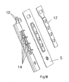
- the guide rail 1 hook-like holding means 13, 15 which are formed from the material which is cut free from the locking windows 12 of the guide rail 1 and bent. These hook-like holding means 13, 15 are formed over at least one edge of the latching window cutout to the guide rail 1.
- FIG. 18 this is for example in FIG. 18 shown where the hook-like holding means 13 are formed on an outlet edge of the inlet slopes of locking webs 14 and the locking window upper edge of the locking window 12 between the successive locking windows 12.
- the free-standing end web of the L-profile in the Z direction is preferably directed in assembly target position down.
- the hook-like holding means 13, 15 are thus formed from the material which is actually separated in the formation of the latching window 12, but according to the invention remains substantially integrally formed on the guide rail 1 to form the hook-like latching means 13, 15.
- the vehicle structure serving for fastening the guide rail 1 or the mounting plate 5 serving for fastening has slots 22 into which the hook-like holding means 13, 15 can be inserted.
- Components of the hook-like holding means 13, 15 engage in the assembly target position areas of the vehicle structure or the vehicle panel 5, so that a secure arrangement and fixation is guaranteed.
- the guide rail 1 is releasably connected at its two longitudinal ends with the vehicle structure or the vehicle panel 5.
- a later described in detail in the installation position is provided at the upper end in the fitting position, while at the lower end a fastening screw 19 is provided, which passes through a corresponding perforation of the guide rail 1 at the lower end.
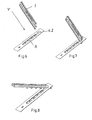
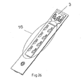
- the guide rail 1 is cranked at its upper end in installed position and forms by the cranking a push-in tab 3, which is insertable into a corresponding recess 4.1 or 4.2 of the vehicle structure or the vehicle panel 5, so that the end of the guide rail 1 with the push-in tab 3, the vehicle structure or the vehicle panel 5 engages under.
- a retaining lug 11 can be unlatched, which serves for further fixation.
- This retaining lug 11 is opposite to the free end of the cranked end of the tuck 3. In assembly target position, it engages components of the vehicle structure or the vehicle panel. 5
- the recess 4.1 is a correspondingly dimensioned transverse slot transverse to the longitudinal rail extension in the body structure 5, in which the insertion tab 3 can be inserted
- the recess 4.2 formed as a longitudinal slot. Accordingly, the cranked end is inserted with the tuck 3 in the manner in the recess 4.2, that the guide rail is rotated by 90 ° about its longitudinal axis, as in FIGS. 6 and 7 seen.
- the cranked end is constricted approximately T-shaped, so that the guide rail 1 in the desired position, the in FIG.
- the vehicle structure or the vehicle panel 5 has a flared tab 21.
- the guide rail 1 with its straight end 20 can be inserted to make the connection. This is clearly visible in the given figures.
- the hook-like holding means 13, 15 preferably protrude toward the vehicle structure forming the fastening plane for the guide rail 1 or toward the vehicle panel 5, preferably protruding at a right angle from the guide rail 1.
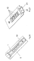
- the hook-like holding means 13 are T-shaped.
- the slots 22 are likewise T-shaped, with their longitudinal webs being directed parallel to the guide rail 1 aligned in the mounting desired direction, for example in FIG FIG. 18 is apparent.
- the hook-like holding means 15 are L-shaped and in pairs at each locking window 12 of the Guide rail formed and cut. The hook variants can not only be issued in conjunction with the latching windows, but optionally also be formed from separate punched out.
- the ends of the hook-like holding means 15 are rectified and aligned parallel to the rail longitudinal extension, wherein the hook mouth is open to the mounting target lower end of the guide rail 1 out.
- a reinforcing member 17 may be arranged, in particular in the form of a reinforcing sheet.
- This reinforcing member 17 has corresponding shape, slots, recesses and / or tab as the body structure 5, so that in the assembly target position, the corresponding fastening means of the guide rail 1 not only the body structure, but also the additional reinforcing member 17 engage below.
- T-shaped recesses 22 engage. Subsequently, the complete guide rail 1 is moved in the Z direction, so that the heads of the hook-like holding means 13 sit in the region of the longitudinal webs of the T-shaped recesses 22. Here, the notched fixing lug 11 also engages under the body structure 5 in the area next to the recess 4.1. For final securing position, the fastening screw 19 is introduced into the corresponding hole.
- the assembly procedure is similar, wherein only, as already stated above, the guide rail 1 is first inserted in a rotated position by 90 ° in the Y direction in the recess 4.2 and then rotated about its longitudinal axis by 90 °, so that the position according to FIG. 8 is reached.
- the insertion tab 3 engages not only the front side (6), as in FIG. 5 shown, but due to their T-shape on both sides (7) behind the wall of the body mold part 5.
- the guide rail 1 is moved to the body structure 5 out and brought into abutment and then moved in the Z direction, so that the hook-like holding means 13 in the perforations 22 are locked.
- the insertion tab 3 can be provided in the region of the offset with beads 9, which extend in the longitudinal direction, to achieve a stiffening. Also, the tuck 3 in the range of cranking with lateral collar or webs. 8 be designed as in FIG. 15 is clarified to achieve the stiffening.
- the tab 3 can also be equipped with molded L-shaped hooks, as in FIG. 18 is clarified, these hooks engage in the final assembly position, the body structure 5, as in FIG. 19 is illustrated.
- the tightening surfaces which cause a tightening torque in the direction of the bodywork 5 or the like in the assembly target position when the guide rail 1 is displaced, can all be beveled in order to achieve an increasing tightening torque during displacement.
- This arrangement is indicated only symbolically by the reference numeral 16.
- stampings 18 can be provided in the upper region of the insertion tab 3 on the body structure 5 or on the insertion tab 3, which bring about tensioning with the corresponding counterpart component in the assembly target position.
- the invention provides a particularly stable height adjuster available, which is easy to assemble, has a high position security even under load conditions and can be inexpensively made of relatively thin material even at low height of the rail cross-section.
Landscapes
- Engineering & Computer Science (AREA)
- Mechanical Engineering (AREA)
- Connection Of Plates (AREA)
- Window Of Vehicle (AREA)
Applications Claiming Priority (1)
| Application Number | Priority Date | Filing Date | Title |
|---|---|---|---|
| DE202010016105U DE202010016105U1 (de) | 2010-12-01 | 2010-12-01 | Höhenversteller für Fahrzeugsicherheitsgurt |
Publications (2)
| Publication Number | Publication Date |
|---|---|
| EP2460698A1 true EP2460698A1 (fr) | 2012-06-06 |
| EP2460698B1 EP2460698B1 (fr) | 2013-04-03 |
Family
ID=43603964
Family Applications (1)
| Application Number | Title | Priority Date | Filing Date |
|---|---|---|---|
| EP20110007479 Not-in-force EP2460698B1 (fr) | 2010-12-01 | 2011-09-15 | Dispositif de réglage en hauteur pour ceintures de sécurité de véhicules |
Country Status (3)
| Country | Link |
|---|---|
| EP (1) | EP2460698B1 (fr) |
| DE (1) | DE202010016105U1 (fr) |
| ES (1) | ES2402705T3 (fr) |
Cited By (1)
| Publication number | Priority date | Publication date | Assignee | Title |
|---|---|---|---|---|
| CN106364447A (zh) * | 2015-07-24 | 2017-02-01 | 比亚迪股份有限公司 | 安全带高度调节器 |
Families Citing this family (3)
| Publication number | Priority date | Publication date | Assignee | Title |
|---|---|---|---|---|
| DE102012001152A1 (de) | 2012-01-21 | 2013-07-25 | Gm Global Technology Operations, Llc | Schnalle für ein Spannband eines Airbags |
| DE102013226882B4 (de) * | 2012-12-20 | 2024-05-23 | Volkswagen Aktiengesellschaft | Verbindungsanordnung eines Bauteils mit einem Karosserieblech |
| CN106627271A (zh) * | 2016-12-29 | 2017-05-10 | 浙江吉利汽车研究院有限公司 | 一种成人儿童两用车辆座椅及车辆 |
Citations (6)
| Publication number | Priority date | Publication date | Assignee | Title |
|---|---|---|---|---|
| EP0685373A1 (fr) | 1994-06-01 | 1995-12-06 | Albert Griesemer | Dispositif de réglage en hauteur d'un renvoi de ceinture de sécurité pour véhicules |
| EP0745520A1 (fr) * | 1995-05-29 | 1996-12-04 | Toyota Jidosha Kabushiki Kaisha | Structure d'absorption de l'énergie de collision dans un dispositif de ceinture de sécurité de véhicule |
| DE19928162A1 (de) * | 1999-06-19 | 2000-12-28 | Schmidt Gmbh R | Vorrichtung zur Höhenverstellung eines Umlenkbeschlages für einen Sicherheitsgurt in Kraftfahrzeugen |
| DE102005040640A1 (de) * | 2005-06-22 | 2007-01-04 | Albert Griesemer | Führungsschiene für den Umlenkbeschlag eines Sicherheitsgurtes für Kraftfahrzeuge |
| DE102006000816B3 (de) * | 2006-01-03 | 2007-04-05 | Albert Griesemer | Führungsschiene für den Umlenkbeschlag eines Sicherheitsgurtes für Kraftfahrzeuge |
| EP2067670A2 (fr) | 2007-12-03 | 2009-06-10 | Key Plastics Lennestadt GmbH & Co. KG | Réglage en hauteur pour une ceinture de sécurité de véhicule |
-
2010
- 2010-12-01 DE DE202010016105U patent/DE202010016105U1/de not_active Expired - Lifetime
-
2011
- 2011-09-15 EP EP20110007479 patent/EP2460698B1/fr not_active Not-in-force
- 2011-09-15 ES ES11007479T patent/ES2402705T3/es active Active
Patent Citations (6)
| Publication number | Priority date | Publication date | Assignee | Title |
|---|---|---|---|---|
| EP0685373A1 (fr) | 1994-06-01 | 1995-12-06 | Albert Griesemer | Dispositif de réglage en hauteur d'un renvoi de ceinture de sécurité pour véhicules |
| EP0745520A1 (fr) * | 1995-05-29 | 1996-12-04 | Toyota Jidosha Kabushiki Kaisha | Structure d'absorption de l'énergie de collision dans un dispositif de ceinture de sécurité de véhicule |
| DE19928162A1 (de) * | 1999-06-19 | 2000-12-28 | Schmidt Gmbh R | Vorrichtung zur Höhenverstellung eines Umlenkbeschlages für einen Sicherheitsgurt in Kraftfahrzeugen |
| DE102005040640A1 (de) * | 2005-06-22 | 2007-01-04 | Albert Griesemer | Führungsschiene für den Umlenkbeschlag eines Sicherheitsgurtes für Kraftfahrzeuge |
| DE102006000816B3 (de) * | 2006-01-03 | 2007-04-05 | Albert Griesemer | Führungsschiene für den Umlenkbeschlag eines Sicherheitsgurtes für Kraftfahrzeuge |
| EP2067670A2 (fr) | 2007-12-03 | 2009-06-10 | Key Plastics Lennestadt GmbH & Co. KG | Réglage en hauteur pour une ceinture de sécurité de véhicule |
Cited By (2)
| Publication number | Priority date | Publication date | Assignee | Title |
|---|---|---|---|---|
| CN106364447A (zh) * | 2015-07-24 | 2017-02-01 | 比亚迪股份有限公司 | 安全带高度调节器 |
| CN106364447B (zh) * | 2015-07-24 | 2020-08-07 | 比亚迪股份有限公司 | 安全带高度调节器 |
Also Published As
| Publication number | Publication date |
|---|---|
| ES2402705T3 (es) | 2013-05-08 |
| DE202010016105U1 (de) | 2011-02-17 |
| EP2460698B1 (fr) | 2013-04-03 |
Similar Documents
| Publication | Publication Date | Title |
|---|---|---|
| EP2576319B1 (fr) | Corps élastique | |
| EP3478533B1 (fr) | Dispositif de réglage en longueur et siège de véhicule | |
| EP2830910B1 (fr) | Siège de véhicule | |
| EP3484742B1 (fr) | Dispositif de réglage longitudinal et siège de véhicule | |
| EP3484744A1 (fr) | Dispositif de réglage longitudinal et siège de véhicule | |
| DE102014008973A1 (de) | Gassackmodul | |
| EP2460698B1 (fr) | Dispositif de réglage en hauteur pour ceintures de sécurité de véhicules | |
| DE102009028534A1 (de) | Befestigungssystem in einem Luft- und Raumfahrzeug | |
| DE102013217399A1 (de) | Verkleidungsbefestigungssystem mit hoher haltekraft | |
| DE102011111781B4 (de) | Höhenversteller für einen Befestigungsbeschlag eines Sicherheitsgurt-Systems | |
| EP2945828B1 (fr) | Dispositif de montage pour un élément d'habillage de paroi latérale d'un véhicule ferroviaire | |
| DE10210781B4 (de) | Befestigungsmittel für einen Sicherheitsgurt | |
| DE29812707U1 (de) | Befestigungsvorrichtung für flächige Bauteile | |
| DE102010055245A1 (de) | Gurt-Schienen-Adapter | |
| DE10329852A1 (de) | Sitzstruktur | |
| DE102006061617A1 (de) | Befestigungsanordnung, insbesondere zum Halten eines Umlenkbeschlags für einen Gurtbandabschnitt eines Sicherheitsgurtes in einem Fahrzeug, sowie Verfahren zum Befestigen eines Umlenkbeschlags an einer Trägerwand | |
| DE102009034584A1 (de) | Befestigungseinrichtung für einen Gurtbandumlenker | |
| EP1619082B1 (fr) | Véhicule avec une fixation par encliquetage verrouillable pour pare-chocs | |
| DE3209351A1 (de) | Fahrzeug mit einem in einer laengsfuehrung gefuehrten sitz und mit sitzbefestigtem sicherheitsgurt | |
| EP3727953B1 (fr) | Module de boucle de ceinture muni d'un limiteur d'effort de ceinture ainsi que procédé de montage d'un module de boucle de ceinture | |
| DE10308678B4 (de) | Drehfallenschloß, insbesondere für Kraftfahrzeug-Fondsitzlehnen | |
| WO2013083265A1 (fr) | Elément de support pour un lève-glace pour véhicule automobile avec structure de renforcement | |
| DE102022108376A1 (de) | Schlosshalter für eine Kraftfahrzeug-Schließeinrichtung | |
| EP0642957B1 (fr) | Dispositif de renvoi latéral réglable en hauteur pour ceintures de sécurité | |
| DE102007048225B4 (de) | Umlenker für das Sicherheitsgurt-System eines Fahrzeuges |
Legal Events
| Date | Code | Title | Description |
|---|---|---|---|
| PUAI | Public reference made under article 153(3) epc to a published international application that has entered the european phase |
Free format text: ORIGINAL CODE: 0009012 |
|
| AK | Designated contracting states |
Kind code of ref document: A1 Designated state(s): AL AT BE BG CH CY CZ DE DK EE ES FI FR GB GR HR HU IE IS IT LI LT LU LV MC MK MT NL NO PL PT RO RS SE SI SK SM TR |
|
| AX | Request for extension of the european patent |
Extension state: BA ME |
|
| 17P | Request for examination filed |
Effective date: 20120620 |
|
| RAP1 | Party data changed (applicant data changed or rights of an application transferred) |
Owner name: INNOVATIVE COMPONENTS TECHNOLOGIES GMBH |
|
| RIC1 | Information provided on ipc code assigned before grant |
Ipc: B60R 22/20 20060101AFI20121106BHEP Ipc: B60R 22/24 20060101ALI20121106BHEP |
|
| GRAP | Despatch of communication of intention to grant a patent |
Free format text: ORIGINAL CODE: EPIDOSNIGR1 |
|
| GRAS | Grant fee paid |
Free format text: ORIGINAL CODE: EPIDOSNIGR3 |
|
| GRAA | (expected) grant |
Free format text: ORIGINAL CODE: 0009210 |
|
| AK | Designated contracting states |
Kind code of ref document: B1 Designated state(s): AL AT BE BG CH CY CZ DE DK EE ES FI FR GB GR HR HU IE IS IT LI LT LU LV MC MK MT NL NO PL PT RO RS SE SI SK SM TR |
|
| REG | Reference to a national code |
Ref country code: GB Ref legal event code: FG4D Free format text: NOT ENGLISH |
|
| REG | Reference to a national code |
Ref country code: AT Ref legal event code: REF Ref document number: 604503 Country of ref document: AT Kind code of ref document: T Effective date: 20130415 Ref country code: CH Ref legal event code: EP |
|
| REG | Reference to a national code |
Ref country code: ES Ref legal event code: FG2A Ref document number: 2402705 Country of ref document: ES Kind code of ref document: T3 Effective date: 20130508 Ref country code: IE Ref legal event code: FG4D Free format text: LANGUAGE OF EP DOCUMENT: GERMAN |
|
| REG | Reference to a national code |
Ref country code: DE Ref legal event code: R096 Ref document number: 502011000555 Country of ref document: DE Effective date: 20130529 |
|
| PG25 | Lapsed in a contracting state [announced via postgrant information from national office to epo] |
Ref country code: SI Free format text: LAPSE BECAUSE OF FAILURE TO SUBMIT A TRANSLATION OF THE DESCRIPTION OR TO PAY THE FEE WITHIN THE PRESCRIBED TIME-LIMIT Effective date: 20130403 |
|
| REG | Reference to a national code |
Ref country code: NL Ref legal event code: VDEP Effective date: 20130403 |
|
| REG | Reference to a national code |
Ref country code: LT Ref legal event code: MG4D |
|
| PG25 | Lapsed in a contracting state [announced via postgrant information from national office to epo] |
Ref country code: FI Free format text: LAPSE BECAUSE OF FAILURE TO SUBMIT A TRANSLATION OF THE DESCRIPTION OR TO PAY THE FEE WITHIN THE PRESCRIBED TIME-LIMIT Effective date: 20130403 Ref country code: GR Free format text: LAPSE BECAUSE OF FAILURE TO SUBMIT A TRANSLATION OF THE DESCRIPTION OR TO PAY THE FEE WITHIN THE PRESCRIBED TIME-LIMIT Effective date: 20130704 Ref country code: LT Free format text: LAPSE BECAUSE OF FAILURE TO SUBMIT A TRANSLATION OF THE DESCRIPTION OR TO PAY THE FEE WITHIN THE PRESCRIBED TIME-LIMIT Effective date: 20130403 Ref country code: IS Free format text: LAPSE BECAUSE OF FAILURE TO SUBMIT A TRANSLATION OF THE DESCRIPTION OR TO PAY THE FEE WITHIN THE PRESCRIBED TIME-LIMIT Effective date: 20130803 Ref country code: NL Free format text: LAPSE BECAUSE OF FAILURE TO SUBMIT A TRANSLATION OF THE DESCRIPTION OR TO PAY THE FEE WITHIN THE PRESCRIBED TIME-LIMIT Effective date: 20130403 Ref country code: SE Free format text: LAPSE BECAUSE OF FAILURE TO SUBMIT A TRANSLATION OF THE DESCRIPTION OR TO PAY THE FEE WITHIN THE PRESCRIBED TIME-LIMIT Effective date: 20130403 Ref country code: NO Free format text: LAPSE BECAUSE OF FAILURE TO SUBMIT A TRANSLATION OF THE DESCRIPTION OR TO PAY THE FEE WITHIN THE PRESCRIBED TIME-LIMIT Effective date: 20130703 Ref country code: PT Free format text: LAPSE BECAUSE OF FAILURE TO SUBMIT A TRANSLATION OF THE DESCRIPTION OR TO PAY THE FEE WITHIN THE PRESCRIBED TIME-LIMIT Effective date: 20130805 |
|
| PG25 | Lapsed in a contracting state [announced via postgrant information from national office to epo] |
Ref country code: LV Free format text: LAPSE BECAUSE OF FAILURE TO SUBMIT A TRANSLATION OF THE DESCRIPTION OR TO PAY THE FEE WITHIN THE PRESCRIBED TIME-LIMIT Effective date: 20130403 Ref country code: PL Free format text: LAPSE BECAUSE OF FAILURE TO SUBMIT A TRANSLATION OF THE DESCRIPTION OR TO PAY THE FEE WITHIN THE PRESCRIBED TIME-LIMIT Effective date: 20130403 Ref country code: RS Free format text: LAPSE BECAUSE OF FAILURE TO SUBMIT A TRANSLATION OF THE DESCRIPTION OR TO PAY THE FEE WITHIN THE PRESCRIBED TIME-LIMIT Effective date: 20130403 Ref country code: HR Free format text: LAPSE BECAUSE OF FAILURE TO SUBMIT A TRANSLATION OF THE DESCRIPTION OR TO PAY THE FEE WITHIN THE PRESCRIBED TIME-LIMIT Effective date: 20130403 Ref country code: CY Free format text: LAPSE BECAUSE OF FAILURE TO SUBMIT A TRANSLATION OF THE DESCRIPTION OR TO PAY THE FEE WITHIN THE PRESCRIBED TIME-LIMIT Effective date: 20130403 Ref country code: BG Free format text: LAPSE BECAUSE OF FAILURE TO SUBMIT A TRANSLATION OF THE DESCRIPTION OR TO PAY THE FEE WITHIN THE PRESCRIBED TIME-LIMIT Effective date: 20130703 |
|
| PG25 | Lapsed in a contracting state [announced via postgrant information from national office to epo] |
Ref country code: EE Free format text: LAPSE BECAUSE OF FAILURE TO SUBMIT A TRANSLATION OF THE DESCRIPTION OR TO PAY THE FEE WITHIN THE PRESCRIBED TIME-LIMIT Effective date: 20130403 Ref country code: SK Free format text: LAPSE BECAUSE OF FAILURE TO SUBMIT A TRANSLATION OF THE DESCRIPTION OR TO PAY THE FEE WITHIN THE PRESCRIBED TIME-LIMIT Effective date: 20130403 Ref country code: DK Free format text: LAPSE BECAUSE OF FAILURE TO SUBMIT A TRANSLATION OF THE DESCRIPTION OR TO PAY THE FEE WITHIN THE PRESCRIBED TIME-LIMIT Effective date: 20130403 |
|
| PLBE | No opposition filed within time limit |
Free format text: ORIGINAL CODE: 0009261 |
|
| STAA | Information on the status of an ep patent application or granted ep patent |
Free format text: STATUS: NO OPPOSITION FILED WITHIN TIME LIMIT |
|
| PG25 | Lapsed in a contracting state [announced via postgrant information from national office to epo] |
Ref country code: IT Free format text: LAPSE BECAUSE OF FAILURE TO SUBMIT A TRANSLATION OF THE DESCRIPTION OR TO PAY THE FEE WITHIN THE PRESCRIBED TIME-LIMIT Effective date: 20130403 Ref country code: RO Free format text: LAPSE BECAUSE OF FAILURE TO SUBMIT A TRANSLATION OF THE DESCRIPTION OR TO PAY THE FEE WITHIN THE PRESCRIBED TIME-LIMIT Effective date: 20130403 |
|
| 26N | No opposition filed |
Effective date: 20140106 |
|
| BERE | Be: lapsed |
Owner name: INNOVATIVE COMPONENTS TECHNOLOGIES G.M.B.H. Effective date: 20130930 |
|
| REG | Reference to a national code |
Ref country code: DE Ref legal event code: R097 Ref document number: 502011000555 Country of ref document: DE Effective date: 20140106 |
|
| PG25 | Lapsed in a contracting state [announced via postgrant information from national office to epo] |
Ref country code: MC Free format text: LAPSE BECAUSE OF FAILURE TO SUBMIT A TRANSLATION OF THE DESCRIPTION OR TO PAY THE FEE WITHIN THE PRESCRIBED TIME-LIMIT Effective date: 20130403 |
|
| REG | Reference to a national code |
Ref country code: FR Ref legal event code: ST Effective date: 20140530 |
|
| REG | Reference to a national code |
Ref country code: IE Ref legal event code: MM4A |
|
| PG25 | Lapsed in a contracting state [announced via postgrant information from national office to epo] |
Ref country code: IE Free format text: LAPSE BECAUSE OF NON-PAYMENT OF DUE FEES Effective date: 20130915 Ref country code: BE Free format text: LAPSE BECAUSE OF NON-PAYMENT OF DUE FEES Effective date: 20130930 |
|
| PG25 | Lapsed in a contracting state [announced via postgrant information from national office to epo] |
Ref country code: FR Free format text: LAPSE BECAUSE OF NON-PAYMENT OF DUE FEES Effective date: 20130930 |
|
| REG | Reference to a national code |
Ref country code: CH Ref legal event code: PL |
|
| PG25 | Lapsed in a contracting state [announced via postgrant information from national office to epo] |
Ref country code: SM Free format text: LAPSE BECAUSE OF FAILURE TO SUBMIT A TRANSLATION OF THE DESCRIPTION OR TO PAY THE FEE WITHIN THE PRESCRIBED TIME-LIMIT Effective date: 20130403 |
|
| PG25 | Lapsed in a contracting state [announced via postgrant information from national office to epo] |
Ref country code: MT Free format text: LAPSE BECAUSE OF FAILURE TO SUBMIT A TRANSLATION OF THE DESCRIPTION OR TO PAY THE FEE WITHIN THE PRESCRIBED TIME-LIMIT Effective date: 20130403 Ref country code: TR Free format text: LAPSE BECAUSE OF FAILURE TO SUBMIT A TRANSLATION OF THE DESCRIPTION OR TO PAY THE FEE WITHIN THE PRESCRIBED TIME-LIMIT Effective date: 20130403 |
|
| PG25 | Lapsed in a contracting state [announced via postgrant information from national office to epo] |
Ref country code: CH Free format text: LAPSE BECAUSE OF NON-PAYMENT OF DUE FEES Effective date: 20140930 Ref country code: MK Free format text: LAPSE BECAUSE OF FAILURE TO SUBMIT A TRANSLATION OF THE DESCRIPTION OR TO PAY THE FEE WITHIN THE PRESCRIBED TIME-LIMIT Effective date: 20130403 Ref country code: LI Free format text: LAPSE BECAUSE OF NON-PAYMENT OF DUE FEES Effective date: 20140930 Ref country code: LU Free format text: LAPSE BECAUSE OF NON-PAYMENT OF DUE FEES Effective date: 20130915 Ref country code: HU Free format text: LAPSE BECAUSE OF FAILURE TO SUBMIT A TRANSLATION OF THE DESCRIPTION OR TO PAY THE FEE WITHIN THE PRESCRIBED TIME-LIMIT; INVALID AB INITIO Effective date: 20110915 |
|
| GBPC | Gb: european patent ceased through non-payment of renewal fee |
Effective date: 20150915 |
|
| PG25 | Lapsed in a contracting state [announced via postgrant information from national office to epo] |
Ref country code: GB Free format text: LAPSE BECAUSE OF NON-PAYMENT OF DUE FEES Effective date: 20150915 |
|
| REG | Reference to a national code |
Ref country code: AT Ref legal event code: MM01 Ref document number: 604503 Country of ref document: AT Kind code of ref document: T Effective date: 20160915 |
|
| PG25 | Lapsed in a contracting state [announced via postgrant information from national office to epo] |
Ref country code: AT Free format text: LAPSE BECAUSE OF NON-PAYMENT OF DUE FEES Effective date: 20160915 |
|
| PG25 | Lapsed in a contracting state [announced via postgrant information from national office to epo] |
Ref country code: AL Free format text: LAPSE BECAUSE OF FAILURE TO SUBMIT A TRANSLATION OF THE DESCRIPTION OR TO PAY THE FEE WITHIN THE PRESCRIBED TIME-LIMIT Effective date: 20130403 |
|
| PGFP | Annual fee paid to national office [announced via postgrant information from national office to epo] |
Ref country code: CZ Payment date: 20191105 Year of fee payment: 9 Ref country code: DE Payment date: 20191129 Year of fee payment: 9 |
|
| PGFP | Annual fee paid to national office [announced via postgrant information from national office to epo] |
Ref country code: ES Payment date: 20191030 Year of fee payment: 9 |
|
| REG | Reference to a national code |
Ref country code: DE Ref legal event code: R119 Ref document number: 502011000555 Country of ref document: DE |
|
| PG25 | Lapsed in a contracting state [announced via postgrant information from national office to epo] |
Ref country code: CZ Free format text: LAPSE BECAUSE OF NON-PAYMENT OF DUE FEES Effective date: 20200915 |
|
| PG25 | Lapsed in a contracting state [announced via postgrant information from national office to epo] |
Ref country code: DE Free format text: LAPSE BECAUSE OF NON-PAYMENT OF DUE FEES Effective date: 20210401 |
|
| REG | Reference to a national code |
Ref country code: ES Ref legal event code: FD2A Effective date: 20220118 |
|
| PG25 | Lapsed in a contracting state [announced via postgrant information from national office to epo] |
Ref country code: ES Free format text: LAPSE BECAUSE OF NON-PAYMENT OF DUE FEES Effective date: 20200916 |